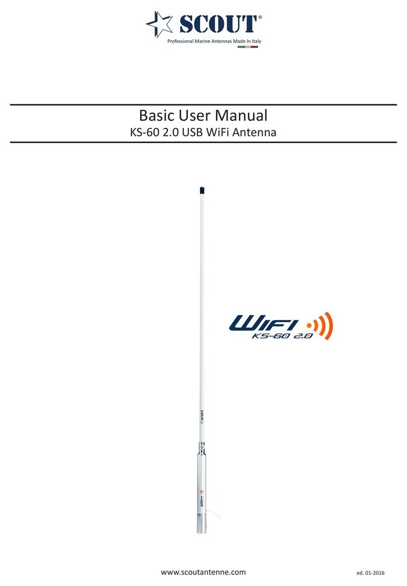
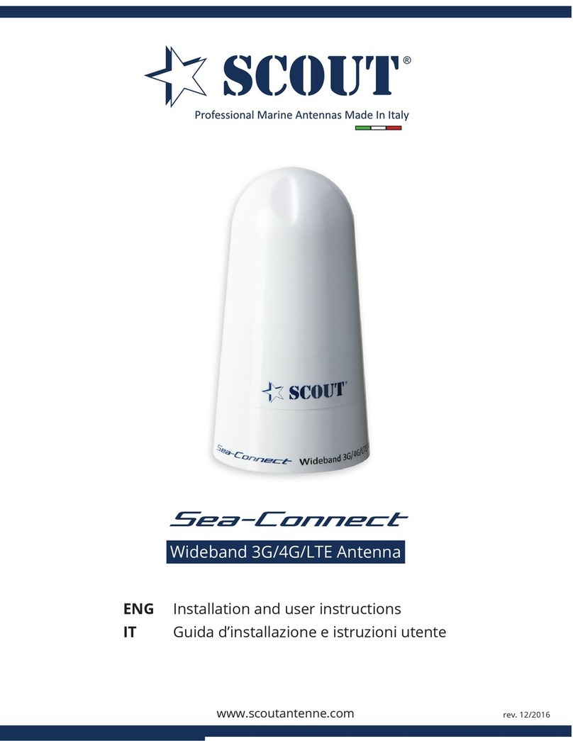
Scout NAV-6 User manual

NAV-6 GPS Marine Antenna
Operator’s manual
ed. 1.2013
Overview
NAV-6 is an acve GPS and GLONASS antenna especially designed for the
marine environment. It combines the high performance GPS patch antenna
and a 27 dB low noise amplier (at 5V DC) into a compact waterproof
antenna with exclusive design.
NAV-6 enables the required GPS funcon for AIS systems, chartploers, and
other navigaonal devices, and helps boost the recepon signal to the GPS
unit, especially when the GPS receiver doesn’t have a good view of the sky.
NAV-6 minimizes temporary loss of signal during navigaon and maintains
the best possible accuracy by having a lock on the greatest number of
satellites.
NAV-6 is supplied with deck mount, mounng set and a 15 m RG58 cable
with TNC male connectors. Standard 1” x 14 threads for pole mounng.
NAV-6 GPS Marine Antenna
Electrical specicaons
Frequencies GPS/GLONASS (1572 - 1610 MHz)
Impedance 50 Ohm
Polarizaon RHCP
LNA Gain 26dB at 3V, 27 dB at 5V
VSWR <1.2:1
Voltage supply 2,7V - 5,5V
Current 15 mA to 25 mA
Power (max.) 138mW
Operang temperature -40°C to +85°C
1
Professional Marine Antennas Made In Italy

2
NAV-6 GPS Marine Antenna
Connecon specicaons
Connector type: TNC male
Cable: RG58
Cable length: 10 m
Mounng type
Any surface
Mechanical specicaons and Dimensions
Max. dimensions: 116mm x 110mm x 74mm (H x L x W)
Material: ABS
Weight: 270 g
Colour: White
About GLONASS
GLONASS, acronym for Global Navigaon Satellite System, is a radio-based satellite navigaon system operated by
the Russian Aerospace Defence Forces. It both complements and provides an alternave to the United States’ Global
Posioning System (GPS) and is the only alternave navigaonal system in operaon with global coverage and of
comparable precision. NAV-6 is capable of receiving and processing GLONASS signals.

3
NAV-6 GPS Marine Antenna
Antenna installaon
Follow the guidelines below to choose a suitable mounng locaon for the NAV-6.
• The NAV-6 is waterproof, and appropriate for above decksmounng.
• Choose a locaon that provides the most unobstructed view of the sky in all direcons:
/RFDWLRQ UHTXLUHPHQWV
:KHQ SODQQLQJ WKH LQVWDOODWLRQ ORFDWLRQ FRQVLGHU WKH IROORZLQJ
7KH *36 UHFHLYHU LV ZDWHUSURRI DQG DSSURSULDWH IRU DERYH GHFNV
PRXQWLQJ
&KRRVH D ORFDWLRQ WKDW SURYLGHV WKH PRVW XQREVWUXFWHG YLHZ RI
WKH VN\ LQ DOO GLUHFWLRQV
'R 127 PRXQW WKH *36 UHFHLYHU DW WKH WRS RI D PDVW
7KH *36 UHFHLYHU VKRXOG EH PRXQWHG DW OHDVW P IW DZD\ IURP
GHYLFHV WKDW PD\ FDXVH LQWHUIHUHQFH VXFK DV PRWRUV JHQHUDWRUV
9+) UDGLR XQLWV DQG RWKHU WUDQVPLWWHUV UHFHLYHUV
(QVXUH WKH *36 UHFHLYHU LV 127 PRXQWHG LQ WKH SDWK RI WKH EHDP
HPLWWHG IURP DQ\ UDGDU VFDQQHU XQLWV
*36 UHFHLYHU PRXQWLQJ RSWLRQV
7KHUH DUH GLIIHUHQW PRXQWLQJ RSWLRQV IRU WKH *36 UHFHLYHU
3ROH PRXQW
)OXVK PRXQW
5DLO PRXQW
3ROH PRXQWLQJ WKH *36 UHFHLYHU
3ROH PRXQWLQJ UHTXLUHV D SROH ZLWK D LQFK 73, WKUHDG 7KH
WKUHDG PXVW QRW H[FHHG PP LQ OHQJWK
56 *36 5HFHLYHU ± ,QVWDOODWLRQ LQVWUXFWLRQV
• GPS antennas should NOT be mounted high up a mast, due to the eects of the boat ‘heeling’ on signal
recepon.
• The NAV-6 should be mounted at least 1 m (3 ) away from devices that may cause interference, such as
motors, generators, VHF radio unitsand other transmiers/receivers.
• Select a locaon out of the radar beam. The radar beam will obstruct or prevent recepon of the GPS signal.
• The locaon should be well away from an Inmarsat antenna. Inmarsat transmission will obstruct or prevent
recepon of the GPS signal.
• Mount the NAV-6 as high as possible to keep it free of interfering objects and water spray, which can obstruct
recepon of the GPS signal if the water freezes.
• Pole mounng requires a pole with a 1 inch 14 TPI thread.

NAV-6 GPS Marine Antenna
SCOUT Telecomunicazioni | Via Toscanini 148, 41019 Soliera, Italy
tel. +39 059 566650 | fax +39 059 565949 | e-mail: scout@scoutantenne.com
Technical specicaons here included may change without prior noce.
SCOUT is a registered trademark.
Reg. n. 009799602
www.scoutantenne.com
4
Professional Marine Antennas Made In Italy
Basic concept of GPS
A GPS receiver calculates its posion by precisely ming the signals sent by GPS satellites high above the Earth. Each
satellite connually transmits messages that include
• the me the message was transmied.
• satellite posion at me of message transmission.
The receiver uses the messages it receives to determine the transit me of each message and computes the distance
to each satellite using the speed of light. Each of these distances and satellites’ locaons dene a sphere. The
receiver is on the surface of each of these spheres when the distances and the satellites’ locaons are correct. These
distances and satellites’ locaons are used to compute the locaon of the receiver using the navigaon equaons.
This locaon is then displayed, perhaps with a moving map display or latude and longitude; elevaon or altude
informaon may be included. Many GPS units show derived informaon such as direcon and speed, calculated
from posion changes.
A good external GPS Antenna is the foundaon of a good GPS Navigaon system. The reasons to need an external
GPS antenna:
• For use in a vehicle where the GPS receiver cannot or will not be placed near a window.
• For use in any place that the receiver doesn’t have a good view of the sky.
• To minimize temporary loss of signal when in a vehicle in moon.
• To maintain the best possible accuracy by having a lock on the greatest number of satellites.
A GPS antenna is a device that helps boost the recepon signal to a GPS unit, whether it is a standalone unit or an
embedded unit. Oen a GPS antenna is used in a situaon where the GPS unit itself is somehow removed from a line
of sight to the sky, as in a car or a yacht, to help the GPS “see” the sky without having to be moved.
Most GPS Devices will came with an internal Antenna with limited sensivity. Also some the internal Antenna & the
GPS Receiver Module will interfere each other and lower the Posion Accuracy.
Table of contents
Other Scout Antenna manuals