Scout Warrior User manual

Warrior
Sport Wheelchair
User and Technical Manual

Scout Mobility BV Page 2 of 17 rev 2018 01
General information
The Warrior Sport Wheelchair is designed for indoor sport use only. It is a high performance
wheelchair and requires sufficient physical and cognitive capabilities from the user.
Optimal and safe use of the wheelchair requires correct setup of the chair, read this instruction
manual carefully before use of the wheelchair.
Have the wheelchair setup properly by your dealer or an experienced engineer.
The wheelchair is standard equipped with a lap belt and it is strongly advised to use this belt when
driving the chair.
Scout Mobility is constantly striving for improvements of the products. Descriptions and pictures in
this manual can therefor differ from the actual situation on your wheelchair.
In case of any doubts regarding technical issues please contact your dealer for more detailed
information. For custom built Warrior sport chairs, always contact your dealer for setting up or
adjusting the chair.
Programming of the wheelchair is only to be done by experienced and skilled engineers. Incorrect
programming can cause dangerous situations and can cause serious injuries. Always contact your
dealer for questions or remarks on programming.

Scout Mobility BV Page 3 of 17 rev 2018 01
Content
General information ................................................................................................................................ 2
Content .................................................................................................................................................... 3
1. Setting up and using the wheelchair ................................................................................................... 4
1.1 Using the Locking Bar .................................................................................................................... 4
1.2 Adjusting rear castors .................................................................................................................... 4
1.3 Cooling Fans .................................................................................................................................. 5
1.4 Charging the Batteries ................................................................................................................... 5
1.5 Removing Cushions ....................................................................................................................... 5
2. Seating Adjustments ............................................................................................................................ 6
2.1 Seat Width ..................................................................................................................................... 6
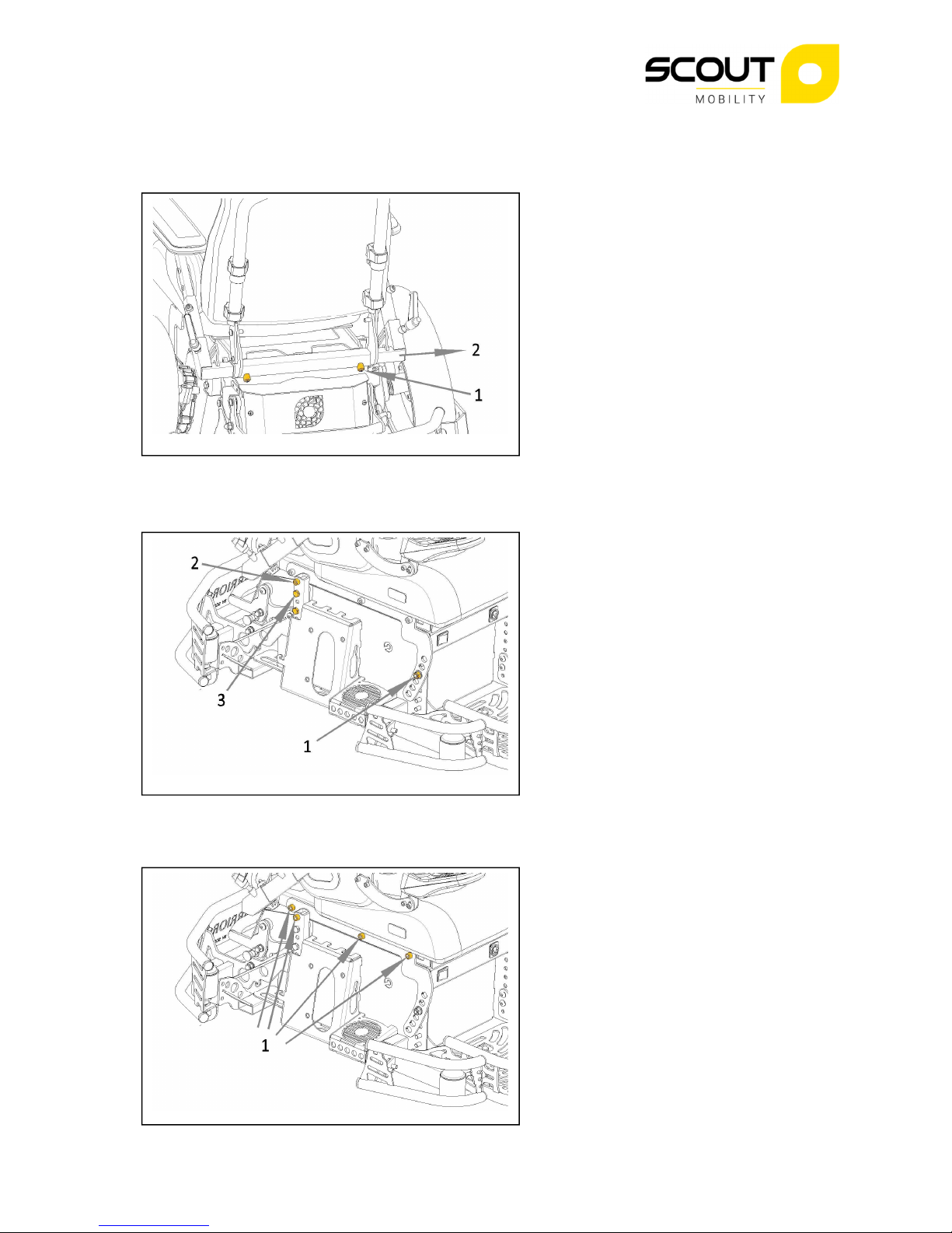
2.2 Seat Height and Seat Angle ........................................................................................................... 6
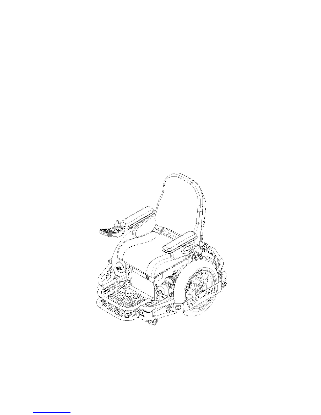
2.3 Seat Depth and Center of Gravity Position ................................................................................... 6
2.4 Backrest Angle ............................................................................................................................... 7
2.5 Armrest Height .............................................................................................................................. 7
2.6 Armrest Depth ............................................................................................................................... 7
2.7 Adjusting Remote Height .............................................................................................................. 8
2.8 Adjusting Remote Depth ............................................................................................................... 8
2.9 Adjusting Remote Angle ................................................................................................................ 8
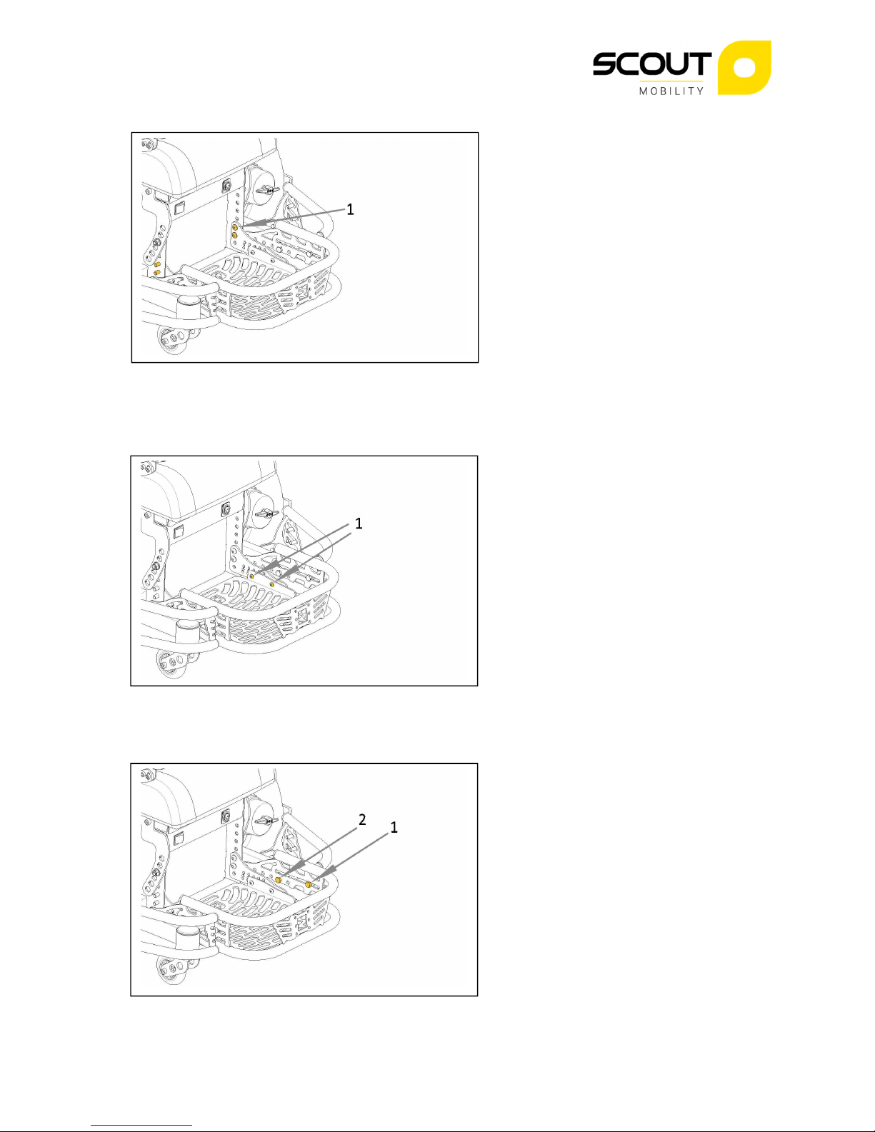
2.10 Adjusting Foot Plate Height ......................................................................................................... 9
2.11 Adjusting Foot Plate Angle and Depth ........................................................................................ 9
2.12 Adjusting Front Protection Bar .................................................................................................... 9
2.13 Adjusting Backrest Height ......................................................................................................... 10
3 Maintenance and Service ................................................................................................................... 10
3.1 Accessing Batteries ...................................................................................................................... 10
3.2 Replacing Tire .............................................................................................................................. 11
3.3 Replacing Motor .......................................................................................................................... 11
3.4 Cleaning or replacing Motor Brushes .......................................................................................... 11
4 Spare Parts and Accessories ............................................................................................................... 12
4.1 Electronic Diagram and Parts ...................................................................................................... 12
4.2 Carrier Parts ................................................................................................................................ 13
4.3 Bumper Parts ............................................................................................................................... 14
4.4 Seating Parts ................................................................................................................................ 15
4.5 Accessories .................................................................................................................................. 16
4.4.1 Fixed Stick Adapter ............................................................................................................... 16

Scout Mobility BV Page 4 of 17 rev 2018 01
1. Setting up and using the wheelchair
1.1 Using the Locking Bar
The Locking Bar provides a possibility to unlock the rear castor position and climb small obstacles and
ramps with the Warrior. When the rear castors are unlocked the maximum speed of the wheelchair
is automatically reduced for safety reasons. It is advised not to use Match drive Profiles when the
Locking Bar is unlocked.
To unlock :
•Pull the Plunger Bolt (1)
•Lift the Locking Bar (2) and release
the Plunger Bolt.
To lock :
•Push the Locking bar down until you
hear the Plunger Bolt Click
1.2 Adjusting rear castors
•For safe and optimal use of the
Warrior wheelchair, the rear castors
need to be correctly adjusted to
ensure stability of the wheelchair
during use.
•Set the tire pressure of the drive
wheels to 2.5 bar
•Have the user sit in the chair
•Lock the rear frame by pushing the
locking lever down until you hear
the securing pin click (see § 1.1)
•Loosen the upper M20 nut (1) on
the rear castor axles.
•Adjust the lower M20 (2) nut until
the rear castor firmly touches the
floor.
•
Retighten the upper nuts (approx.
25 – 30 Nm)
Note :
Wear on the drive wheel tires, tire pressure and user weight can influence the correct height position
of the rear castors. It is important that the correct adjustment of the rear castors is checked before
every use of the chair.

Scout Mobility BV Page 5 of 17 rev 2018 01
1. Cooling Fans
•
Both motors and the Power Module
have a fan for optimal cooling to
extend the life of these
components.
•
The cooling fans have an on off
switch (1) and a fuse (2) at the front
of the chair. Always use the cooling
during games and training sessions.
•
After the match or training, always
keep the fans running for at least 10
minutes.
•
The cooling fans are all identical and
•
interchangeable.
1.4 Charging the Batteries
•The Warrior is standard supplied
with a 12 A charger. For this charger
an external charging socket (1) is
present in the wheelchair.
•The charging socket in the remote
(2) may only be used for chargers
less than 12 A.
1.5 Removing Cushions
Seat Cushion :
•Lift seat Cushion firmly up at front
(1)
•Pull seat cushion away from
backrest (2)
Backrest :
•Slide clips on backrest frame
upward (3)
•Remove back rest cushion (4)

Scout Mobility BV Page 6 of 17 rev 2018 01
2. Seating Adjustments
2.1 Seat Width
•Loosen set screws (1) at back of
seat frame.
•Slide armrest supports to required
width (2)
•Re tighten screws (1).
2.2 Seat Height and Seat Angle
•Remove bolts and spacer (1) at
front of the seat frame
•Loosen (but not remove) the bolts
(2) at the rear of the seat frame
•Remove the bolts (3) from the
square tubes
•Hold the seat frame in the desired
height and tighten the bolts (4) in
the square tubes
•Put the seat frame in the desired
angle and tighten the bolts and
spacer (1) at the front of the seat
frame
2. Seat Depth and Center of Gravity Position
•Loosen but do not remove the bolts
(1) at both sides of the seat frame.
•Slide the front seat frame forward
and/or the rear frame rearward for
the required position
•Retighten the bolts (1)

Scout Mobility BV Page 7 of 17 rev 2018 01
2.4 Backrest Angle
•Loosen the screws in the backrest
(1)
•Remove the small screws (2)
•Set the backrest in the required
angle (4 different positions) and re
tighten the small screws
2.5 Armrest Height
•Loosen set screw (1)
•Set arm rest at required height (2)
•Re tighten screw
•Re route cable if needed.
2.6 Armrest Depth
•Loosen the screws (1)
•Slide the armpad in the required
position (2)
•Re tighten the screws

Scout Mobility BV Page 8 of 17 rev 2018 01
2.7 Adjusting Remote Height
•Loosen the screw (1)
•Remove screw (2)
•Put remote in required position
•Re tighten screws
2.8 Adjusting Remote Depth
•Loosen the screws (1)
•Slide remote in required position
•Re tighten screws
•Re route cable if needed
2.9 Adjusting Remote Angle
•Loosen the screws (1)
•Rotate remote in required position
•Re tighten screws

Scout Mobility BV Page 9 of 17 rev 2018 01
2.10 Adjusting Foot Plate Height
•Loosen and remove the screws (1)
•Put the foot Plate in the required
position
•Retighten the screws
•
2.11 Adjusting Foot Plate Angle and Depth
•Loosen screws (1)
•Remove the screws (2)
•Set Foot plate in the required
position in angle and depth
•Check foot plate ground clearance
for free ball height. If needed adjust
foot plate height (see 2.10)
•Retighten screws
2.12 Adjusting Front Protection Bar
•Loosen screws (1)
•Remove screws (2)
•Set Protection Bar in required depth
position
•Retighten screws

Scout Mobility BV Page 10 of 17 rev 2018 01
2.1 Adjusting Backrest Height
•Loosen but do not remove screws
(1) on both sides of backrest
•Slide backrest cushion in required
position
•Retighten screws (do not
overtighten!)
•For removal of backrest cushion and
easier sliding of cushion slide clips
(2) upward
Maintenance and Service
.1 Accessing Batteries
•Remove Seat Cushion (see § 1.5)
•Remove Power Module Cover (1)
and disconnect fan
•Disconnect buscable from Power
Module
•Remove screws (2) on both sides of
seat frame
•Flip entire seat frame to the front of
the chair (3) and make sure it is
secure
•Remove Battery cover (velcro)

Scout Mobility BV Page 11 of 17 rev 2018 01
.2 Replacing Tire
•Remove Side Protector (1)
•Remove wheel bolts (2)
•Release tire pressure
•Split rim by removing inside rim
bolts
•Replace tire (be aware of rotation
direction!)
•Use Loctite to secure all wheel
bolts
•Retighten bolts with 25 Nm
. Replacing Motor
•Remove Tire (see 3.2)
•Remove central bolt and remove
Hub (1)
•Disconnect Motor from Power
Module
•Remove the Cooling Block by
opening the clamp (2)
•Remove Tie raps
•Remove three Motor Bolts (3) and
remove motor
•Secure new motor to frame
•Assemble Cooling Block with clamp
•Assemble and secure wheel hub
with tab washer
.4 Cleaning or replacing Motor Brushes
•To clean all brushes the motor must
be disassembled from frame
•Remove plug (1) from motor
•Take out carbon brush
•Clean brush opening with
compressed air

Scout Mobility BV Page 12 of 17 rev 2018 01
4 Spare Parts and Accessories
Only standard general parts are shown in this section. For custom built chairs, Spare Parts can be
ordered on request. Contact your dealer for ordering details on parts for custom built chairs.
For ordering parts or getting information always remember that left side of wheelchair is left side
when sitting in the chair.
4.1 Electronic Diagram and Parts
Part Code Description
4100529
Bus Cable R
-
net 1.5 m
4101137
Bus Cable R
-
net 2.5 m
4100337
Power Harness
4100562
Fuse Harness (w thout fuse)
4101056
Blade Fuse 100 A
4100282
78 Ah Battery
4101842
Inh b t Sw tch
Rear Frame
4101608
Brushless Fan
4101623
Illum nated Sw tch
4101423
Fuse Holder
(
Fan
)
4101837
Blade Fuse 1 A
4101790
Ma n Harness Sport Cha r
4100451
Power Module R
-
net
4100503
Color LCD Remote R
-
net
(JSM)
4101218
LED Remote R
-
net
(JSM)

Scout Mobility BV Page 13 of 17 rev 2018 01
4.2 Carrier Parts
Nr
Part Code Description
1
4100436
Motor Left
2
4100437
Motor R ght
3
4100673
Carbon Brushes Set
4
4101767
Wheel Sport Cha r 3.00x10 Left
5
4101830
Wheel Sport Cha r 3.00x10 R ght
6
4102000
T re 3.00x10
7
4100190
Wheel
8
4101769
Rear F
ork Sport Cha r
9
4101793
Front Fork Sport Cha r

Scout Mobility BV Page 14 of 17 rev 2018 01
4. Bumper Parts
Nr
Part Code Description
1
4101808
S de Protector Left
2
4101809
S de Protector R ght
3
4101810
S de Protector Mount ng Beam
4
4101669
Front Bumper
5
4101680
S de
Bumper Left
6
4101684
S de
Bumper R ght
7
4101674
Rear Bumper
8
410176
0
Name Plate

Scout Mobility BV Page 15 of 17 rev 2018 01
4.4 Seating Parts
Nr
Part Code Description
1
4101773
Seat Cush on
Mount ng set
2
4100865
Seat Cush on
36 x 45
2
4100870
Seat Cush on
39 x 45
2
4100872
Seat Cush on
42 x 48
3
4101854
Backrest Cush on
36 x 45
3
4101824
Backrest Cush on
39 x 45
3
4101855
Backrest Cush on
42 x 45
4
4101825
Backrest Cush on Mount ng Set
5
4100619
Arm Pad 30 cm
6
4101795
S de Cush on Sport
7
4101294
L ftable Clamp ng Lever M8
8
4101821
Seat
Plate Sport Cha r
9
4100884
Lap Belt 1.90 m

Scout Mobility BV Page 16 of 17 rev 2018 01
4.5 Accessories
4.5.1 Fixed Stick Adapter
Part code 4101889

Scout Mobility BV Page 17 of 17 rev 2018 01
Dealer contact details:
If there is no information here you can
contact Scout Mobility B.V. for the
nearest dealer address.
Scout Mobility B.V.
Kanaalstraat 101D
5711EG Someren
The Netherlands
T +31(0)6 22 15 21 83
info@Scout Mobility.com
www.scoutmobility.com
Table of contents
Other Scout Wheelchair manuals