1
INDEX
1. INTRODUCTION .........................................................................................4
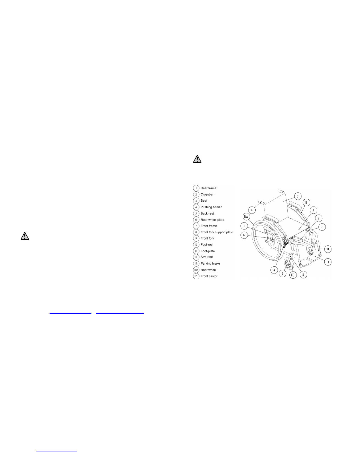
1.1 D
ESCRIPTION
.........................................................................................4
1.2 F
EATURES
..............................................................................................6
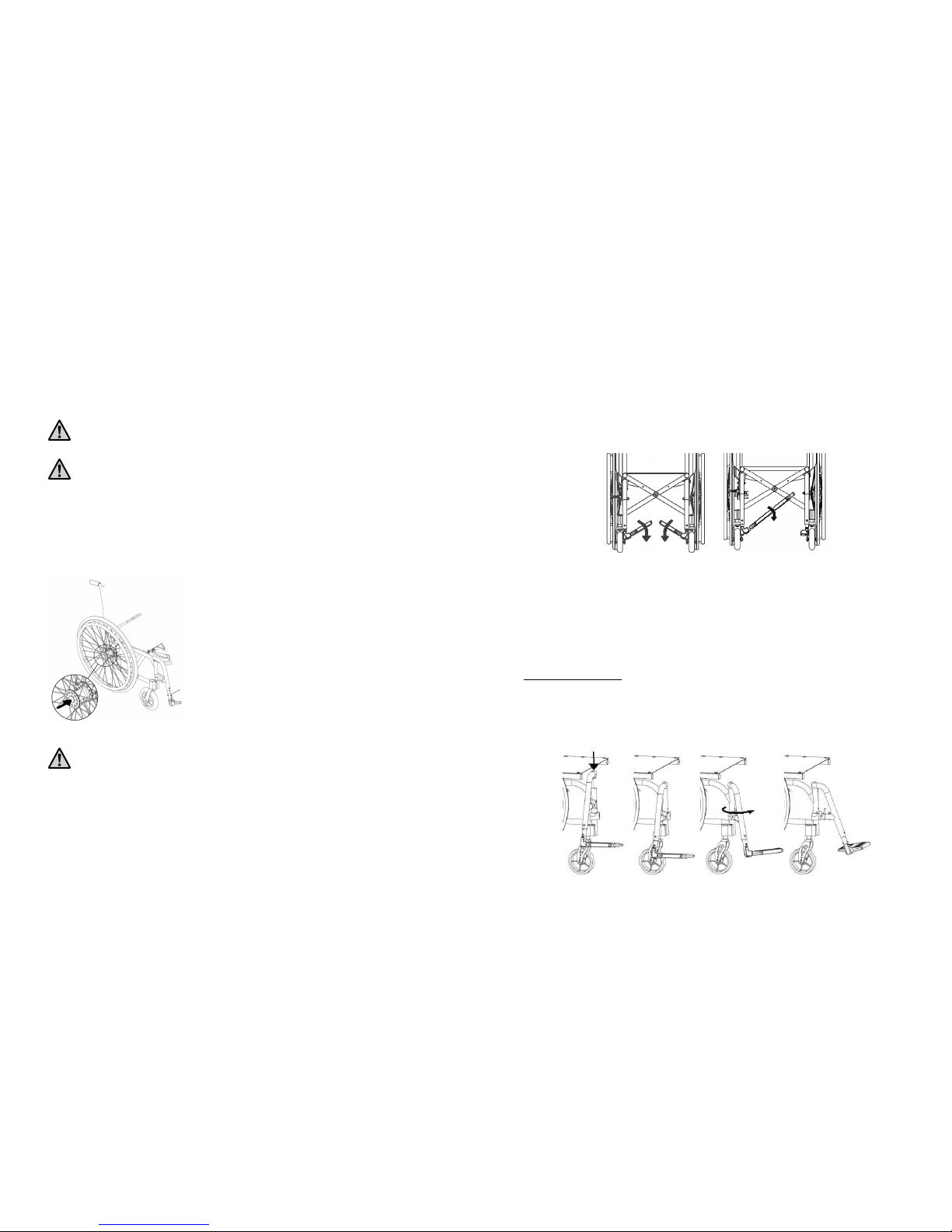
2. PREPARATION FOR USE..........................................................................6
2.1 W
HEELCHAIR OPENING
..........................................................................6
2.2 W
HEELCHAIR FOLDING
..........................................................................6
2.3 T
YRE PRESSURE CHECK
..........................................................................7
2.4 R
EAR WHEELS ASSEMBLY CHECK
...........................................................7
2.5 F
OOT
-
REST POSITIONING
........................................................................8
2.6 B
RAKES CHECK
......................................................................................9
2.7 A
CCESSORIES CHECK
.............................................................................9
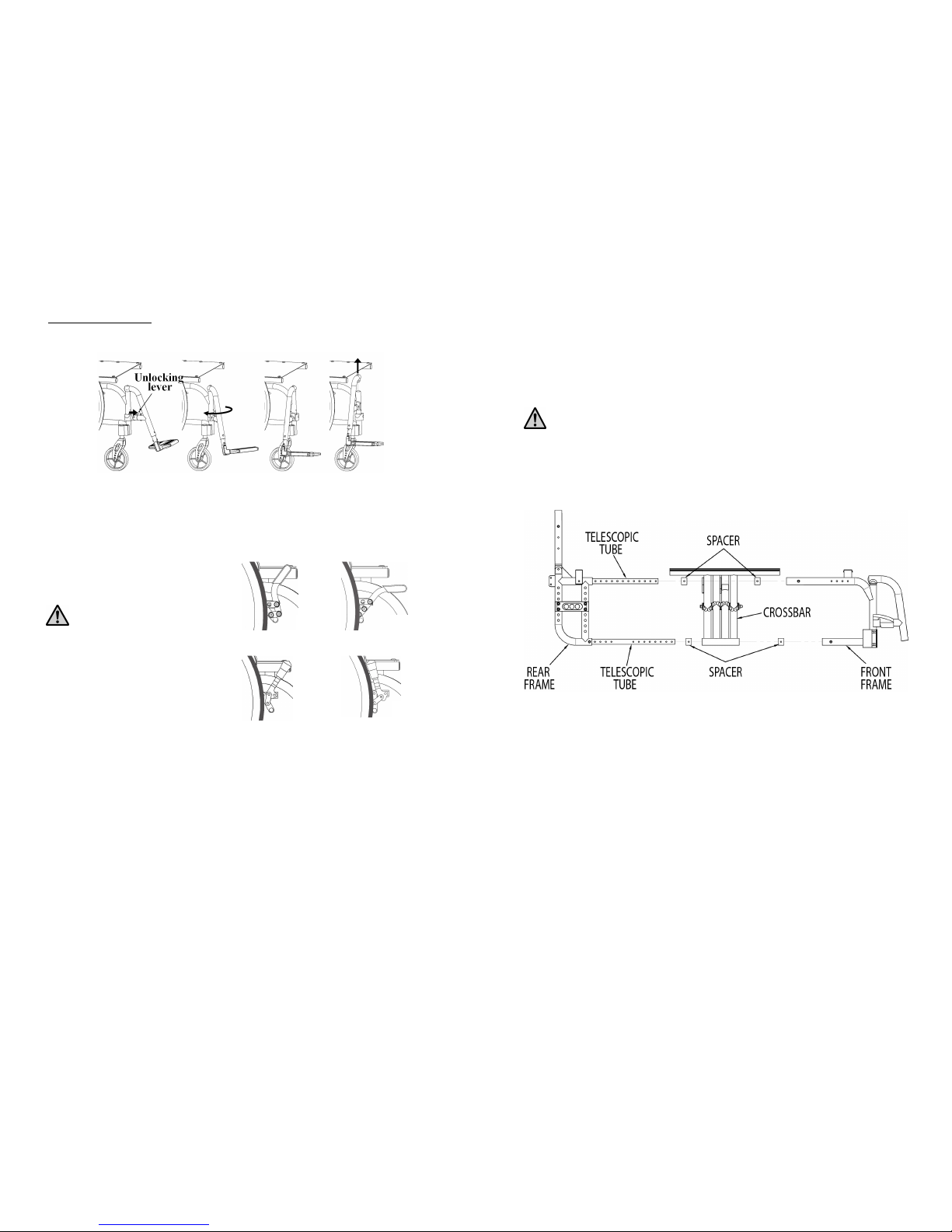
3. SETTING UP ...............................................................................................10
3.1 F
RAME DEPTH ADJUSTMENT
.................................................................10
3.2 R
EAR SEAT HEIGHT ADJUSTMENT
.........................................................13
3.3 G
RAVITY CENTRE ADJUSTMENT
...........................................................13
3.4 F
RONT SEAT HEIGHT ADJUSTMENT
.......................................................14
3.5 F
RONT FORK SUPPORT PLATE ADJUSTMENT
.........................................14
3.6 S
IDE GUARD ADJUSTMENT
...................................................................15
3.7 B
RAKES ADJUSTMENT AND MAINTENANCE
..........................................15
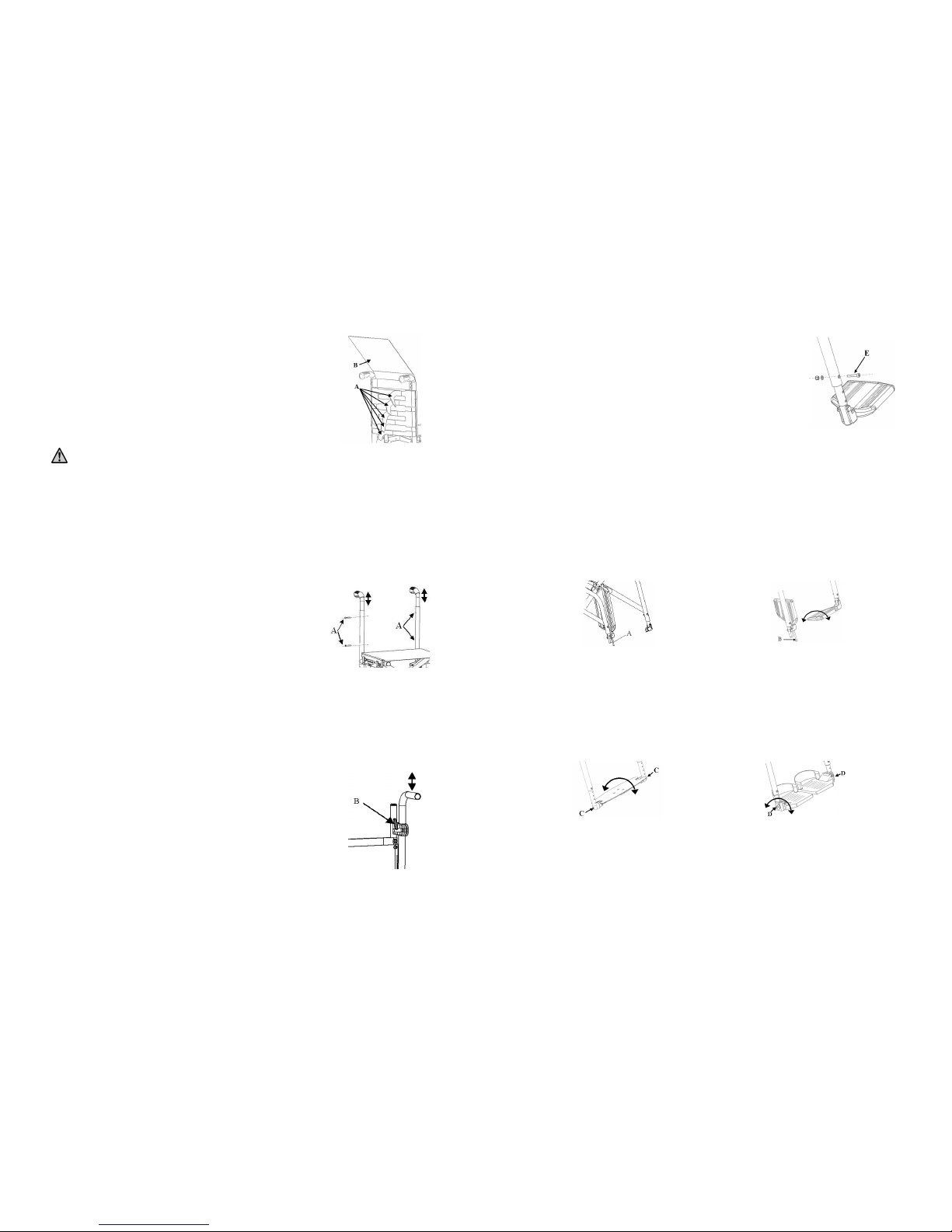
3.8 S
EAT UPHOLSTERY ADJUSTMENT AN REPLACEMENT
............................16
3.9 B
ACK
-
REST TENSION ADJUSTMENT
......................................................17
3.10 B
ACK
-
REST HEIGHT ADJUSTMENT
........................................................17
3.11 H
EIGHT ADJUSTABLE PUSHING HANDLES
.............................................17
3.12 F
OOT
-
PLATE TO SEAT DISTANCE ADJUSTMENT
.....................................18
3.13 F
OOT
-
PLATE TILT ADJUSTMENT
...........................................................18
4. ARM-REST..................................................................................................19
4.1 D
ETACHABLE ARM
-
REST
......................................................................20
4.2 T
IP
-
UP ARM
-
REST
.................................................................................20
4.3 H
EIGHT ADJUSTABLE ARM
-
REST
..........................................................20
4.4 “L”
TYPE ARM
-
REST
.............................................................................21
5. ANTI-TIP DEVICE.....................................................................................22
5.1 C
URVED REAR FRAME ANTI
-
TIP DEVICE
...............................................22
5.2 C
URVED REAR FRAME ANTI
-
TIP DEVICE
...............................................23
5.2.1 Curved rear frame anti-tip device adjustment................................23
5.2.2 Telescopic end terminal adjustment ...............................................23
5.3 S
TRAIGHT REAR FRAME ANTI
-
TIP DEVICE
.............................................23
5.3.1. Height adjustment anti-tip device...................................................24
2
6. DOUBLE PUSHRIM SINGLE DRIVE.....................................................25
7. HINGED BACK-REST...............................................................................26
8. SMALL WHEEL FOR NARROW PASSAGES WITH LEVER............26
9. UNBALANCING SYSTEM........................................................................27
10. EXTENDED WHEEL PLATE...................................................................27
11. STRETCHED BAR .....................................................................................27
12. ELEVATING FOOT-REST .......................................................................28
13. TABLE..........................................................................................................28
14. ABDUCTOR ................................................................................................29
15. LATERAL SUPPORT ................................................................................30
16. HEAD-REST................................................................................................31
17. SPOKES GUARDS......................................................................................31
18. WC SEAT.....................................................................................................31
19. USE OF THE WHEELCHAIR ..................................................................32
20. WARNING TO REDUCE THE RISKS ASSOCIATED WITH MISUSE
OF THE WHEELCHAIR...........................................................................34
21. MAINTENANCE, INSPECTIONS AND CONTROLS...........................35
22. CLEANING INSTRUCTRION..................................................................36
23. TECHNICAL SERVICE.............................................................................37
24. WARRANTY TERMS................................................................................37
25. PACKAGING, SHIPPING AND DELIVERY..........................................38
26. MATERIALS DIFFERENTIATION.........................................................38