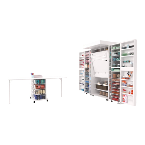
ScrapBox HER HOBBYBOX User manual

Her HobbyBox Assembly Instructions
UPDATED: JANUARY 2019
oh happy day
YOU’VE RECIEVED THE HER HOBBYBOX!
We’ve done our best to make sure our furniture is easy and fun to build so you can
start crafting as quickly as possible. After assembling your Her HobbyBox, please
email us about your experience at yvonne@theoriginalscrapbox.com.
For a companion video for these instructions, visit this link (link is case sensitive):
http://bit.ly/HHBInstructions
If you have questions regarding your Her HobbyBox, don’t hesitate to contact us.
customerservice@theoriginalscrapbox.com
www.theoriginalscrapbox.com
U.S.A./Canada: 801-226-2686 M-F 9am-5pm MST
Germany: +49 40 69632955
Thank you for choosing our products to help you make space to dream and create.
We wish you many happy, organized hours of crafting!
The Original ScrapBox Team

2Proprietary, patented product and assembly instructions. Do not copy or distribute.
You’ll need both a phillips & flathead screwdriver.
Always build with the help of a friend.
If you need any help with your build, contact
our customer service department.
They are experts and happy to help you!

3Proprietary, patented product and assembly instructions. Do not copy or distribute.
*Other hardware comes attached to wood panels:
-8 large hinges for waterfall shelving boxes with 48-12mm screws
18
x
Pins
18
x
Cams
7
x
Acrylic Guards
A
B
68
x
Shelf Pegs
C
208
x
12mm (1/2 inch)
15
x
19
x
Angle Brackets
Door and Table Hinges
Screws for all angle
brackets and hinges
D
7
x
18mm (3/4 inch)
1 for Black Table Strap
6 for Lower Back Panel
8
x
Metal Shelf Holders
32
x
Dowels
Designer Door Knobs
2
x
E
12
x
35 mm (1 1/3 inch)
2 for CB6
4 for CB7’s
4 for CB8’s
2 for CB9
15
x
15
x
Washers
16 mm (3/5 inch)
Screws and
Washers for
Acrylic Guards
on Left Door
Table Legs
1x
Table
1
x
1
x
Back Panel Center Strips
5
x
Wheels for center box.
Light Kit
1
x
1
x
4
x
Custom Fit
LED Light
Electrical Wire Clips
Transformer
2
x
14mm Screw
Adhesive Strip
Large Adhesive Strip
1
x
Table strap
Wheel and Table Leg Bolts
28
x
20 - for wheels
8 - for table legs
Clear Plastic Totes
Fabric Totes
x22
OR
Velcro Zipper Pouches
x7
Tote Set
MAY CONTAIN EXTRA HARDWARE
6 - Square
1 - Rectangle
6 - 12 5/8 x 12 1/2 x 3
8 - Notions Totes
24 - Notions Dividers
8 - Shoebox Totes
16 - Shoebox dividers
6 - 12 1/4 x 12 1/4 x 3
8 - Notions Totes
16 - Notions Dividers
8 - Shoebox Totes
Plastic Metal Rod Holders
6
x
3
x
Metal Rods 15 1/4”
Optional:
Comes attached to wood panels:
8 large hinges for waterfall shelving boxes with (48) 12mm screws
MAY CONTAIN EXTRA HARDWARE

4Proprietary, patented product and assembly instructions. Do not copy or distribute.
1. Install 6 pins into CB1 (Center Box side panel) as shown
-Install 7 dowels into CB1 as shown
2. Place CB4 (Center Box upper shelf) onto CB1 with pins and dowels inserting into CB4
CB1
= Pin Holes
Center box
1
CB1
CB4
= Screw Holes
2
This side of the
panel is the front
of Her HobbyBox
Back of HerHobbyBox
This side of the
panel is the back
of Her HobbyBox
*Finished edges
should face
towards the front
of Her HobbyBox.
Check ALL edges
before installing
Front of Her HobbyBox

5Proprietary, patented product and assembly instructions. Do not copy or distribute.
3. Insert 2 cams into holes as shown. With a flathead screwdriver, turn cams 180 degrees
and lock into place. Attach Angle Brackets with (6) 12mm screws with a phillips screw-
driver.
*All brackets should be installed by screwing in 3 screws without tightening them.
Then screw in the 3 other screws and tighten all six. DO NOT OVER TIGHTEN.
4. Attach CB3 (Center Box lower table shelf) as shown. Install 2 cams and 1 angle bracket
with (6) 12mm screws. Make sure grooved edge is facing down as shown.
3 – Insert 2 cams into holes as shown. With a FLATHEAD SCREWDRIVER turn 180 degrees and lock into place.
Attach Angle Bracket with 6 - 12 mm (1/2”) screws with a PHILLIPS SCREWDRIVER . (All brackets should be
installed by screwing in 3 screws without tightening them. Then screw in the 3 other screws and tighten all six.
DO NOT OVER TIGHTEN.)
4 – Attach CB3 (Center Box lower table shelf) as shown. Install 2 cams and 1 angle bracket with 6 - 12 mm
screws. Make sure the grooved edge is facing down as shown.
CB1
CB4
180°
Cam
3
12mm (1/2 inch)
CB1
CB4
4
CB3

6Proprietary, patented product and assembly instructions. Do not copy or distribute.
5. Install 5 wheels to CB5 (Center Box base) using (20) 1/2” bolts.
*IMPORTANT: do not tighten, leave wheels loose until cams are installed.
6. Install CB5 (Center Box base) onto pins and dowels. Use 2 cams to lock into place,
turning 180 degrees. Now tighten all bolts on 2 lower and center wheels.
CB1
CB4
CB3
CB5
6
CB5
1/2 Bolts
5
5 - Install 5 wheels to CB5 (Center Box base) using 20 1/2” bolts. IMPORTANT: DON’T TIGHTEN, leave wheels
loose until cams are installed.
6- Install CB5 (Center Box base) onto pins and dowels. Use 2 cams to lock into place, turning 180 degrees. Now
tighten all bolts on 2 lower and center wheels.

7Proprietary, patented product and assembly instructions. Do not copy or distribute.
7. Install CB6 (Center Box lower shelf divider) by inserting 2 dowels at the top to be attached to
CB3 into dowel holes. Line up CB6 with pilot holes of CB5. By hand, screw in (2) 35mm screws to
CB5 to find pilot holes in CB6.
*Screw in with Phillips screwdriver. Do not over tighten. Be careful to screw in straight so
as to prevent splitting the wood. Take your time! Install 2 angle brackets attaching CB1 to CB5.
Be certain to use a friend for the next step to avoid damaging your box!
8. Insert 2 dowels each into the CB8s (Center Box upper dividers). Install lower CB8 first with (2)
35mm screws, by hand, then tighten with a screwdriver. Make sure the 3 angle bracket holes are
facing toward CB1. Take your time to screw straight to aviod splitting the wood.
Install upper CB8 (with angle bracket holes facing up) using (2) 35mm screws,
first by hand, then with screwdriver. Install angle brackets for CB8s.
CB1
CB4
CB3
CB5
CB6
CB8
CB8
35mm (1 1/3 inch)
8
12mm (1/2 inch)
CB1
CB4
CB3
CB5
Dowel Holes
Dowels
35mm (1 1/3 inch)
CB6
7
Screw Pilot Holes
7 - Install CB6 (Center Box lower shelf divider) by inserting 2 dowels at the top to be attached to CB3 into dowel
holes. Line up CB6 with pilot holes of CB5. Hand screw 2 - 35mm (1/1/3”) screws into CB5 to find pilot holes
in CB6. Screw in with PHILLIPS SCREWDRIVE. DO NOT OVER TIGHTEN. BE CAREFUL TO SCREW IN
STRAIGHT AS TO NOT SPLIT THE WOOD. TAKE YOUR TIME! Install 2 angle brackets attaching CB1 to
CB5.
MUST USE 2 PEOPLE FOR NEXT STEP TO AVOID DAMAGES
8 - Insert 2 dowels each into the CB8’s (Center Box upper dividers). Install lower CB8 first with 2 - 35mm screws,
by hand, then tighten with screwdriver. Make sure the 3 angle bracket holes are facing toward CB1.) TAKE YOUR
TIME TO SCREW IN STRAIGHT SO THE WOOD DOES NOT SPLIT.
- Install upper CB8 (with angle bracket holes facing up) with 2 - 35 mm screws, by hand, then with screwdriver.
Install angle brackets for CB8’s.

8Proprietary, patented product and assembly instructions. Do not copy or distribute.
9. Attach first CB7 (Center Box lower shelf divider) with angle bracket holes facing CB1
with 2 dowels for CB4 and (2) 35mm screws for CB3. Do not tighten these screws until
all three dividers are in place. Again, take your time.
Attach CB9 (Center Box middle divider) with 2 dowels and (2) 35mm screws
Attach other CB7 (with angle bracket holes facing up) using 2 dowels and (2)
35mm screws.
Now tighten all (6) 35mm screws. Remember: DO NOT OVER TIGHTEN
9 – Attach CB7 (Center Box Lower shelf divider) with angle bracket holes facing CB1) with 2 dowels for
CB4 and 2- 35mm screws for CB3. DO NOT TIGHTEN THESE SCREWS UNTIL ALL THR EE DIVIDERS ARE IN
PLACE. AGAIN, TAKE YOUR TIME!
- Attach CB9 (Center Box middle divider) with 2 dowels and 2 -35mm screws.
- Attach other CB7 (with angle bracket holes facing up) with 2 dowels and 2 - 35 mm screws.
-NOW TIGHTEN ALL 6 – 35MM SCREWS. REMEMBER: DO NOT OVER TIGHTEN.
CB1
CB4
CB3
CB5
CB6
CB8
CB8
9
CB7
CB9
CB7
35mm (1 1/3 inch)
*Finished edges facing out
*Unnished Edge

9Proprietary, patented product and assembly instructions. Do not copy or distribute.
10. Place CB14 (Base Front Panel) onto dowel on CB1
Install 7 dowels in CB14, CB5, CB3 and CB4
Add 3 angle brackets with 12mm screws to CB8 (1) and CB7 (2)
10 - Place CB14 (Base Front Panel) onto dowel on CB1.
- Install 7 dowels in CB14, CB5, CB3, and CB4.
- Add 3 Angle brackets with 12 mm screws to CB8 (1) and CB7 (2).
CB1
CB4
CB3
CB5
CB6
CB8
CB8CB7
Angle
Brackets
12mm (1/2 inch)
Dowels
CB14
10

10 Proprietary, patented product and assembly instructions. Do not copy or distribute.
11. Add 6 pins to CB2 (Center Box right side panel). Turn over and carefully fit onto built
section, making sure all pins and dowels are securely in.
Add 6 cams and lock into place, turning 180 degrees
Tighten last two wheels on CB5 now
Add 2 angle brackets attaching CB14 to CB1 and CB5 to CB1
11 -
Add 6 pins to CB2 (Center Box Right Side Panel). TURN OVER and carefully t onto built section, making
sure all pins and dowels are securely in.
- Add 6 Cams and lock into place, turning 180 degrees.
CB1
CB4
CB3
CB5
CB6
CB8
CB8CB7
CB14
CB2
CB2
11
-Tighten last two wheels on CB5 now.
-Add 2 angle brackets attaching CB14 to CB1 and CB5 to CB1

11 Proprietary, patented product and assembly instructions. Do not copy or distribute.
12. Add:
2 angle brackets attaching CB5 to CB2,
1 angle bracket attaching CB14 ot CB2
Place CB11 (Upper Back panel WITHOUT hole) into upper groove of CB1.
Add Long Back Panel Center Strip
Slide CB10 (upper back panel WITH hole) into CB2 groove and Center Strip as shown.
*CB10 and CB11 will NOT be flush with CB1 and CB2. They will extend out about 1/4”. Make sure
CB10 and CB11 are secure into the groove of CB3.
– Place CB11 (Upper Back Panel WITHOUT hole) into upper groove of CB1.
- Add LONG Back Panel Center Strip.
- Slide CB10 (Upper Back Panel WITH hole) into CB2 groove and Center Strip as shown.
(CB10 and CB11 will NOT b ush with CB1 and CB2. They will extend out about 1/4”. Make sure the CB10
and CB11are secure into groove of CB3.)
CB1
CB4
CB3
CB5
CB6
CB8
CB7
CB2
CB11
Long Back Panel Center Strip
CB10
12
12 - Add: angle brackets attaching CB5 to CB2
1 angle bracket attaching CB14 to CB2
CB14

12 Proprietary, patented product and assembly instructions. Do not copy or distribute.
13. Add CB13 (lower back panel WITHOUT hole) into groove of CB1 (make sure the
screw pilot holes are on the left as shown).
Place SHORT Back Panel Center Strip onto CB13
Slide CB12 (lower back panel WITH hole) into groove of CB2 and Center Strip
Screw in (6) 18mm screws to Lower Back Panels.
*HAND SCREW IN all 6 screws at the beginning to find pilot holes in CB5, then tighten.
DO NOT OVER TIGHTEN.
13 – Add CB13 (Lower Back Panel WITHOUT hole) into groove of CB1. (Make sure the screw pilot holes are
on left as shown.)
- Place SHORT Back Panel Center Strip onto CB13.
- Slide CB12 (Lower Back Panel WITH hole) into groove of CB2 and Center Strip.
- Screw in 6 – 18 mm (3/4”) screws into Lower Back Panels. HAND SCREW all 6 screws at the beginning
to nd pilot holes in CB5, then tighten. (DO NOT OVER TIGHTEN.)
CB3
CB5
CB6
CB2
CB10
CB11
CB12
CB13
Short Back Panel Center Strip
18mm (3/4 inch)
13

13 Proprietary, patented product and assembly instructions. Do not copy or distribute.
**Rotate Center Box onto back as shown**
14. Install 4 remaining angle brackets using (36) 12mm screws into areas shown above
**LOWER CENTER BOX ONTO BACK PANELS AS SHOWN BELOW. **
14 – Install 4 remaining Angle Brackets using 36 - 12 mm screws into areas shown above.
Angle
Brackets
CB2
CB1
14

14 Proprietary, patented product and assembly instructions. Do not copy or distribute.
15. Prepare table to be installed onto Center Box by:
1. Attach legs with (8) 15mm bolts (DO NOT OVER TIGHTEN)
2. Attach black table strap with one (1) 18mm screw
3. Install 3 hinges half way by screwing in (3) 12mm screws to each hinge with
BARREL of hinge FACING OUT.
TABLE
15 – Prepare table to be installed onto Center box by:
1 – Attach legs with 8 - 15 mmbolts. (DO NOT OVER TIGHTEN)
2 – Attach black Table Strap with 18 mm screw.
3 – Install 3 hinges half way by screwing in 3 - 12 mm screws into each hinge with
BARREL of hinge FACING OUT.
15mm bolts
18mm (3/4 inch)
12mm
15

15 Proprietary, patented product and assembly instructions. Do not copy or distribute.
WITH A FRIEND
16. Attach table to Center Box by having 1 person hold the table next to hinge pilot holes
on CB3. The other person attaches remaining (9) 12mm screws to table hinges into CB3
Carefully set table down onto Center Box and lift Center Box upright onto wheels.
WITH 2 PEOPLE:
16 – Attach table to Center Box by having 1 person hold the table next to hinge pilot holes on CB3. The 2 nd
person then attaches remaining 9 - 12 mm screws to table hinges into CB3.
Carefully set table down onto center box and LIFT CENTER BOX onto wheels.
CB2
CB1
CB3
16
12mm

16 Proprietary, patented product and assembly instructions. Do not copy or distribute.
17. Add
4 dowels to CB1 and CB2 (CB8s should already have 4 dowels)
4 pins to Center Box Top. TURN OVER
Place carefully into dowels on top of Center Box. Make sure pins and dowels are
secure and Back Panels are snug into Center Box Top groove.
Add 4 cams and lock into place. Add 4 angle brackets to CB1, CB8(1), CB8(2) and
CB2, connecting to Box Top using 12mm screws.
17 – Add 4 dowels to CB1 and CB2. (CB8 ’s should already have 4 dowels)
- Add 4 pins to Center Box Top. TURN OVER.
- Place carefully into dowels on top of Center Box. Make sure pins and dowels are
secure and Back Panels are snug into Center Box Top groove.
- Add 4 cams and lock into place.
- Add 4 Angle Brackets to CB1, CB8, CB8, and CB2, connecting to Box Top using 12 mm screws.
CB2
CB1
CB8
CB8
Center Box Top
Center Box Top
17

17 Proprietary, patented product and assembly instructions. Do not copy or distribute.
18. Attach 4 hinges to Left Waterfall box and 4 hinges to Right Waterfall box using (3)
12mm screws per hinge (Make sure barrel is facing out).
18 – Attach 4 Hinges to Left Waterfall box and 4 Hinges to Right Waterfall box using
3 - 12 mm screws per hinge. (Make sure Barrel is facing out).
18
Left Box Right Box
12 mm

18 Proprietary, patented product and assembly instructions. Do not copy or distribute.
WITH A FRIEND
19. Attach Left Box to Center Box and then Right Box to Center Box with 4 hinges using
12mm screws.
WITH 2 PEOPLE:
19 - Attach Left Box to Center Box, and then Right Box to Center Box with 4 Hinges and 12 mm screws.
19
12mm
Right Box
Left Box

19 Proprietary, patented product and assembly instructions. Do not copy or distribute.
20. Attach Left Box with Shelves to Left Waterfall Box using 12mm screws. 4 hinges
should already be attached to the waterfall box.
See acrylic guard install in above picture (7 acrylic guards, (14) 10mm screws and 14
washer included in hardware).
Install crystal door knobs.
DO NOT OVER TIGHTEN. DAMAGES DURING ASSEMBLY MAY NOT BE
COVERED BY WARRANTY.
20 – Attach Left Box with Shelves to LEFT Waterfall Box using 12mm screws. 4 hinges should already be
attached to the waterfall box.
See acyrlic guard install in above picture (7 acrylic guards, 14 - 10 mm
screws and 14 washers included in hardware.)
Left Box with Shelves
20
Acrylic guard install
*Always use washer
to prevent acrylic guard
from cracking
12mm
Install crystal door knobs.
DO NOT OVER TIGHTEN. DAMAGES DURING ASSEMBLY MAY NOT BE COVERED BY WARRANTY.

20 Proprietary, patented product and assembly instructions. Do not copy or distribute.
21. Attach Right Box with Velcro to Right Waterfall Box using 12mm screws. Again, 4
hinges are already attached to the waterfall box.
21 – Attach Right Box with Velcro to RIGHT waterfall box with 12 mm screws. Again, 4 hinges are already
attached to the waterfall box.
21
Right Box with Velcro
12mm
Table of contents
Other ScrapBox Indoor Furnishing manuals
Popular Indoor Furnishing manuals by other brands

Whittier Wood
Whittier Wood 1555a Assembly instructions

ManoMano
ManoMano Tarnby 518216 Assembly instructions

Takara Belmont
Takara Belmont MIRAKU SC-S81XL installation instructions

Gami
Gami BROOKLYN H52 Assembly instructions

Nemschoff
Nemschoff Ava 917-66A instructions

Sapphire Sleep
Sapphire Sleep 300 user manual