manuals.online logo
Brands
  1. Home
  2. •
  3. Brands
  4. •
  5. ScrapBox
  6. •
  7. Indoor Furnishing
  8. •
  9. ScrapBox SEW STATION User manual

ScrapBox SEW STATION User manual

UPDATED: DEC 2019
oh happy day
YOU’VE RECEIVED THE SEW STATION!
It’s already time for your first project. Let’s get to work!
To make things easy, we’ve broken down the Sew Station assembly instructions
into simple steps. All of the hardware you will need can be found in one bag.
If you have questions at any point of the assembly process, don’t hesitate to
reach out to our customer service team. They are the friendliest bunch of
furniture experts and will be happy to help you.
customerservice@theoriginalscrapbox.com
www.theoriginalscrapbox.com
U.S.A./Canada: 801-226-2686 M-F 9am-5pm MST
We are excited for you to enjoy your inspiring new workspace and can’t wait to
see pictures! Share your photos on Facebook and Instagram and don’t forget
to tag @theoriginalscrapbox. Happy crafting!
The Original ScrapBox Team
2Proprietary, patented product and assembly instructions. Do not copy or distribute.
HARDWARE YOU’LL NEED
TOOLS YOU’LL NEED (NOT INCLUDED)
x12
Hinges
x4
Guide Spaces
(for drawer rails)
x1
White Magnetic
Door Catch and Strike
(screws included)
x1
Door support wheel
w/ 2 screws
x2
Table Legs
w/ adjustable foot
x2
16” Drawer Rail Guides
x2
270° Door Hinges
x2
270° Door Hinge
Mounting Plates
x1
Door Handle
(DreamBox Pull)
x2
1” Screws
x19
Connecting
Bolts
x84
13mm Euro Screws
(72 for hinges)
(12 for spacers)
x8
Table Leg
Screws
x1
Silver Barrel Lock
Catch w/ Screws
x4
Wheels w/ U Channel
Plates
& 4 Machine Screws
x16
Angle Bracket
Screws
x4
Angle Brackets
x3 Inner
Shelf Supports
x3 Left
Shelf Supports
x3 Right
Shelf Supports
x1
Sash Lock
(screws included)
Our furniture is designed to
be built with two people.
Please don’t try to build
alone.
A Friend
(not included)
Phillips head
Screw Driver
Electric Drill with
Phillips bit
R
L* ADDITIONAL HARDWARE FOR
MACHINE LIFT AND SPOOL DRAWER
LISTED LATER.
x1
Silver Barrel Lock
for WorkBox 3.0 and
Her HobbyBox owners
x4
Flathead Hinge
Screws
(2) 1/2 inch
wrenches
3
Proprietary, patented product and assembly instructions. Do not copy or distribute.
Before you build your Sew Station & Spool Holder, you’ll need to separate the drawer rails into
two pieces to be installed individually. The rails are comprised of three pieces. The outer and
intermediate pieces don’t separate. The inner piece can be completely removed.
Remove the inner track by pressing the black lever
inside the track up or down to unlock it. Slide the
track free from the intermediate and outer tracks.
Ok, all set!
outer track
intermediate track
inner track
4Proprietary, patented product and assembly instructions. Do not copy or distribute.
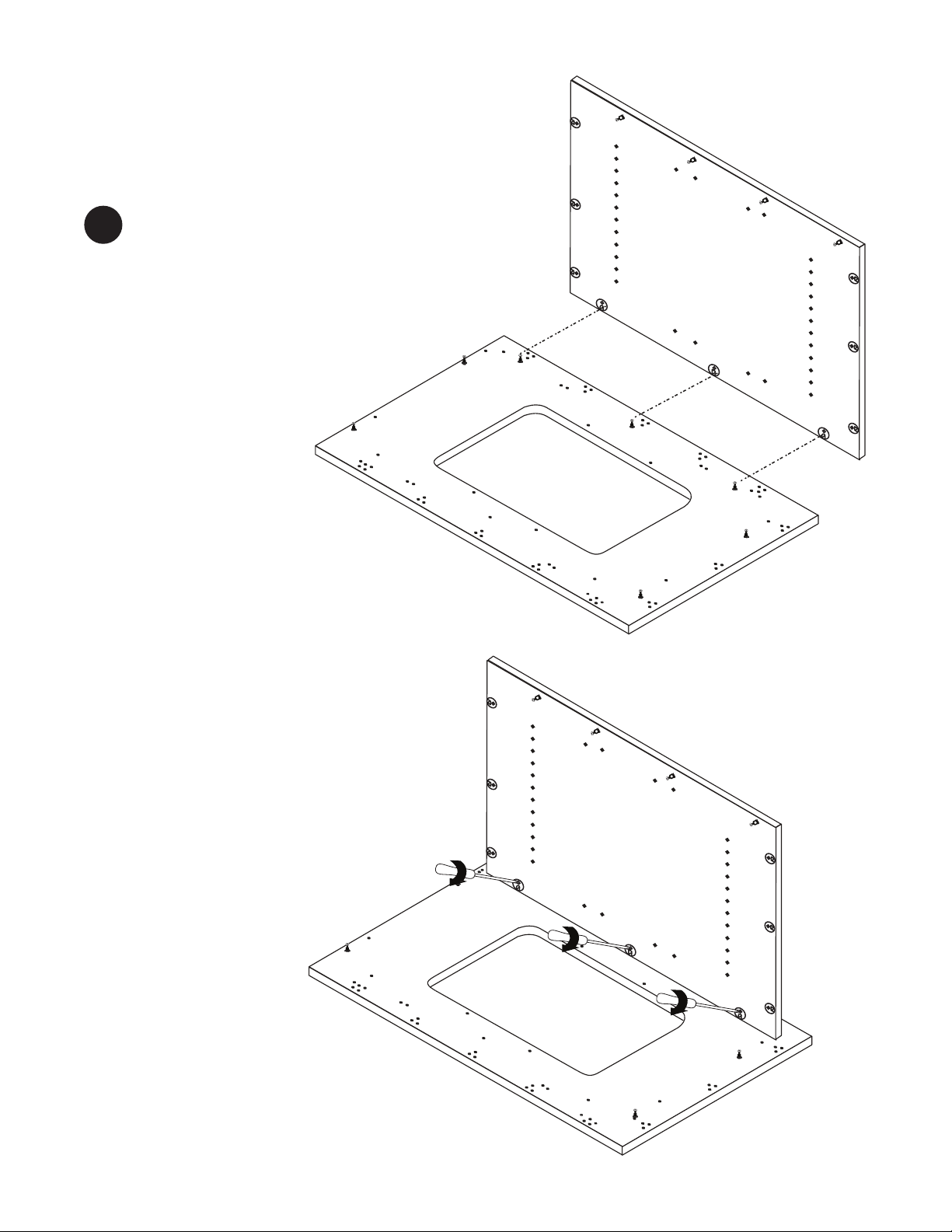
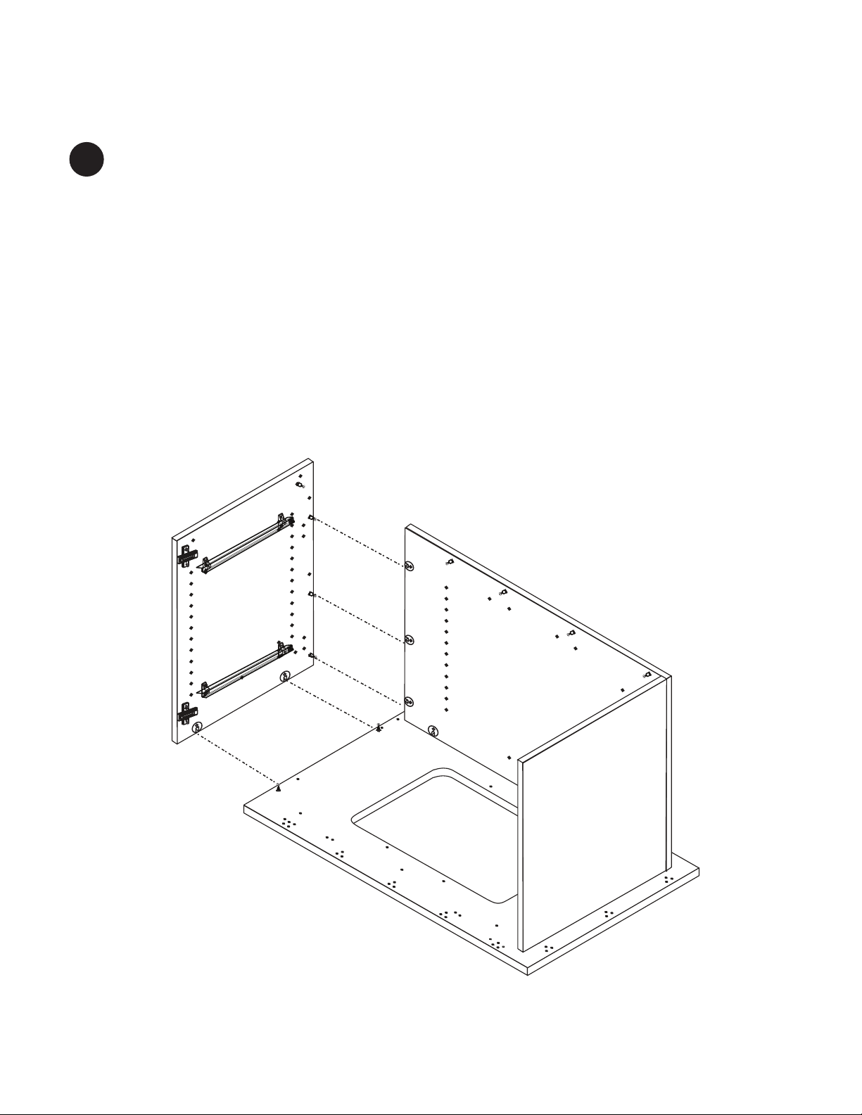
Back
Side 1
Side 2
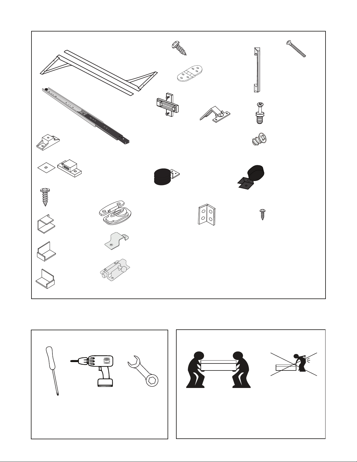
Build on a blanket or rug to protect your wood panels.
Use a Phillips head screwdriver to insert (12) connecting bolts
into the corresponding holes in Side 1, Side 2 and Back as shown.
Turn clockwise to tighten.
Now, pause to do some planning.
Decide how you want to configure your Sew Station. There are some steps that need to be done
differently depending on which configuration you choose.
If you’re planning to use your Sew Station on the left side of your DreamBox, use Left Side Configu-
ration (the side table will extend to the right). If you’d like to use your Sew Station on the right side of
your DreamBox, use Right Side Configuration (the table will extend to the left.
If you wish to use your sewing machine knee lift, spool holder needs to be installed on Side 1.
As always, if you have questions, please reach out to our furniture experts. They are happy to assist
you.
1
5
Proprietary, patented product and assembly instructions. Do not copy or distribute.
Top
RIGHT CONFIGURATION
(turn Top so that side table hinge holes are on the right)
LEFT CONFIGURATION
(turn Top so that side table hinge holes are on the left)
side table hinge holes
Use a Phillips head screwdriver to insert
(7) connecting bolts into the corresponding
holes in Top. Turn clockwise to tighten.
2
Top
6Proprietary, patented product and assembly instructions. Do not copy or distribute.
If you use a machine knee lift, spacers and rails will be installed on Side 1 for spool
holder. Be sure to install door hinge mounting plates on Side 1 if you have a left
configuration and a machine with knee lift (as in step 10) before you install rails.
Screw (8) euro screws into (4) spacers just until screw is protruding through to the
other side of the spacer before installing on side panel. Install (4) spacers on Side 2.
3
LEFT SIDE CONFIGURATION
RIGHT SIDE CONFIGURATION
Separate mounting plate from door hinge by pressing down
silver lever (notice how it connects to make door install easier on
step 20). Install (2) Door Hinge Mounting Plates to Side 2 as
shown using a Phillips screwdriver & the included screws.
Long side of mounting plate faces inside of panel.
Side 2
x2
Side 2
x4
Side 1
(For machine knee lift sewists)
7
Proprietary, patented product and assembly instructions. Do not copy or distribute.
RIGHT CONFIGURATION
LEFT CONFIGURATION
Side 2
Side 2
Install (2) Inner/Intermediate tracks over
the spacers on Side 2 using (4) euro screws.
4
8Proprietary, patented product and assembly instructions. Do not copy or distribute.
Back
Insert a phillips head screwdriver
at a slight angle and turn clockwise
to tighten.
Line up (3) built-in cams in Back with corre-
sponding connecting bolts in Top. Slide Back
into place.
5
Top
Top
Back
9
Proprietary, patented product and assembly instructions. Do not copy or distribute.
Side 1
Slide Side 1 onto (2) connecting bolts in right side of Top and (3) built-in cams in Back.
Turn clockwise to tighten.
Note: If you chose “Right Side Configuration” the side table hinge holes will be on the same
side of the Top as Side 1. If you chose “Left Side Configuration” the side table hinge holes will
correspond with Side 2.
6
Top
Back
10 Proprietary, patented product and assembly instructions. Do not copy or distribute.
Side 2
Slide Side 2 onto (2) connecting bolts in left side of Top and (3) built-in cams in Back.
Turn clockwise to tighten.
Note: If you chose “Left Side Configuration” the side table hinge holes will be on the same
side of the Top as Side 2. If you chose “Right Side Configuration” the side table hinge holes
will correspond with Side 1.
7
Top
Back
Side 1
11
Proprietary, patented product and assembly instructions. Do not copy or distribute.
Top
Side 1
Side 2
Back
Top
Side 1
Side 2
Back
Base
Using an electric phillips head screw-
driver, install (4) angle brackets as
shown using ((16) included screws.
8
Lift Base onto (6) connecting bolts in
Sides and Back. Tighten built-in cams
to secure Base.
9
Lift Base
into place
12 Proprietary, patented product and assembly instructions. Do not copy or distribute.
Install magnetic catch with
(2) included screws.
Install magnetic catch with
(2) included screws.
Top
Side 1
Side 2
Back
Base
Top
Side 2
Side 1
Back
Base
RIGHT SIDE CONFIGURATION
10
Install (2) mounting plates to Side 1
using (2) euro screws each.
10
Catch is adjustable. Move toward edge of Top.
13
Proprietary, patented product and assembly instructions. Do not copy or distribute.
Top
Side 1
Side 2
Back
Base
Side Table
Install barrel
lock receiver
Top
Side 2
Side 1
Back
Side Table
Install barrel
lock receiver
RIGHT SIDE CONFIGURATION
LEFT SIDE CONFIGURATION
Attach Side Table using (3)
hinges and (18) euro screws. DO
NOT tighten screws all the way
at first. Once table is attached
tighten one screw in each hinge
and repeat until all screws are
tight.
Attach Side Table using (3) hinges and (18)
euro screws. DO NOT tighten screws all the
way at first. Once table is attached tighten
one screw in each hinge and repeat until all
screws are tight.
11
11
Base
14 Proprietary, patented product and assembly instructions. Do not copy or distribute.
Back
Side 2
Side 1
Table
Base
Side Table
Attach Table using (5) hinges and (30) euro screws. DO NOT tighten screws all the way at
first. Once table is attached tighten one screw in each hinge and repeat until all screws are
tight.
12
Attach (1) table leg to each table using (4) table leg screws for each table leg. Install side
table leg into the set of pre-drilled holes indicated so that the table leg opens toward the
front side of the Sew Station. Be careful not to over-screw.
13
Table Leg Holes
for Right Side Configuration
Table Leg Holes
for Left Side Configuration
(LEFT SIDE CONFIGURATION PICTURED)
15
Proprietary, patented product and assembly instructions. Do not copy or distribute.
**larger hole
towards the outside
Back
Side 2
Side 1
Back Table
Side 2
Side Table
Install (4) wheels using the included screws.
Install with the larger hole towards the outside.
Manually tighten.
14
CAUTION HEAVY: With two people fold tables and turn onto front of Sew Station.
Carefully lift onto 4 wheels. Unlock wheels to have station move freely. Lock wheels to continue to build.
16 Proprietary, patented product and assembly instructions. Do not copy or distribute.
x6
x4
Insert (6) rubber pads
into metal arms
Line up metal arms with
metal center.
Install (4) bearing wheels onto the front
2 holes on each metal arm using (4) washers, bolts
and nuts. Using 2 - 1/2" wrenches tighten the bolt
and the nut. Make sure the black side (lock thread)
of nut is on the outside. The silver side is toward
the Bearing Wheel. Bearing wheel should spin
freely once tightened. IMPORTANT: Placement of
the washer is important so bearing spins freely and
doesn't burn out your motor.
a b
c
Next, you’ll assemble and install the machine lift & assembly the spool drawer.
Metal Arm
Metal Arm
Metal Arm
Metal Arm
Center
Nut
Bearing Wheel
Washer
Bolt
HARDWARE YOU’LL NEED
x6
Rubber
pads
x8
Bolts
x8
Washers
x8
Bearing
wheels
x2
Cords
x8
Nuts
x18
1/2“ Screws. (4) for metal center, (6) for lift
Shelf, (8) for installing lift to Sew Station.
x4
Plastic Cord
Holders
x2
Screws for
lift control
17
Proprietary, patented product and assembly instructions. Do not copy or distribute.
Use (2) 1/2” screws to fasten metal
centerpiece to the power lifter.
Install from back of lifter. Make
sure 2 metal lips are flush with the
white plastic lifter. There are no
drill holes. Please self tap.
x2
Install (4) bearing wheels onto the back
2 holes on each metal arm. Use (4) washers
and (4) nuts.
d
e
18 Proprietary, patented product and assembly instructions. Do not copy or distribute.
Side 1
Side 2
Table
Top
Install power lifter using (8) 1/2” screws. If you have a left side configuration the unused pilot
holes in the base will be visible after install on the left. If you have a right side configuration the
unused pilot holes in the base will be on the right . This will assure your lifter is centered.
Connect the top of the center lift guide to the Sew Station with (2) 1/2" screws. Be careful to
screw SLOWLY and not strip the back panel.
Side Table
15
19
Proprietary, patented product and assembly instructions. Do not copy or distribute.
Install cords to power lift motor.
Plug in and raise the lift.
Use (6) screws to fasten sewing
shelf onto the power lifter by
pushing down on shelf and
screwing from under shelf.
Shelf
Shelf
16
Install lift control on right or left side of the Top.
Please install lift control switch on the OPPOSITE
side of the rails. Attach cord using plastic cord
holders to top and back of Sew Station.
20 Proprietary, patented product and assembly instructions. Do not copy or distribute.
Spool Base Spool Side 1 Spool Side 2 Spool Shelf
Spool Back
Use a phillips screwdriver to install
(14) connecting bolts to corresponding
holes in Spool Base, Spool Side 1
Spool Side 2, and Spool Back.
SPOOL HOLDER DRAWER ASSEMBLY
a
HARDWARE YOU’LL NEED
x2
Inner Drawer
Rail Guides
x14
Connecting
Bolts
x16
Spool Holders
x8
Guide screws
x1
Door Knob w/
Screws
x4
Inner Shelf Supports
x2
Left Shelf Supports
x2
Right Shelf Supports
x2
Acrylic Guards
R
L

Other ScrapBox Indoor Furnishing manuals

ScrapBox SIDE TABLE User manual

ScrapBox

ScrapBox SIDE TABLE User manual

ScrapBox DreamCart User manual

ScrapBox

ScrapBox DreamCart User manual

ScrapBox HER HOBBYBOX User manual

ScrapBox

ScrapBox HER HOBBYBOX User manual

ScrapBox WORKBOX 3.0 Side Table User manual

ScrapBox

ScrapBox WORKBOX 3.0 Side Table User manual

ScrapBox WorkBox 3.0 User manual

ScrapBox

ScrapBox WorkBox 3.0 User manual

Popular Indoor Furnishing manuals by other brands

Rauch AD980.5ZS4 Assembly instructions

Rauch

Rauch AD980.5ZS4 Assembly instructions

Costway HW64140-2 user manual

Costway

Costway HW64140-2 user manual

Crosley Furniture CO1001A quick start guide

Crosley Furniture

Crosley Furniture CO1001A quick start guide

IMG Group Scandi Assembly instructions

IMG Group

IMG Group Scandi Assembly instructions

Walker Edison YASB8B Assembly instructions

Walker Edison

Walker Edison YASB8B Assembly instructions

Eclipse 091009 Assembly instruction

Eclipse

Eclipse 091009 Assembly instruction

Whittier Wood Furniture McKenzie Alder 1613AUF Assembly instructions

Whittier Wood Furniture

Whittier Wood Furniture McKenzie Alder 1613AUF Assembly instructions

CONFORAMA 3 DRW CHEST Assembling instructions

CONFORAMA

CONFORAMA 3 DRW CHEST Assembling instructions

Living Spaces SEDONA 4136 manual

Living Spaces

Living Spaces SEDONA 4136 manual

Furinno 11048WH Assembly instruction

Furinno

Furinno 11048WH Assembly instruction

Furniture of America Winifred CM6342-SF Assembly instructions

Furniture of America

Furniture of America Winifred CM6342-SF Assembly instructions

modway MOD-5473 quick start guide

modway

modway MOD-5473 quick start guide

Cooper Lighting Interior Wall Luminaire 641-WP Specification sheet

Cooper Lighting

Cooper Lighting Interior Wall Luminaire 641-WP Specification sheet

Strictly Beds & Bunks Canopy Bed Single Assembly instructions

Strictly Beds & Bunks

Strictly Beds & Bunks Canopy Bed Single Assembly instructions

Abble 300527 Assembly instruction

Abble

Abble 300527 Assembly instruction

Loll Designs LOLLYGAGGER ROCKER ASSEMBLY INSTRUCTIONS & PRODUCT INFO

Loll Designs

Loll Designs LOLLYGAGGER ROCKER ASSEMBLY INSTRUCTIONS & PRODUCT INFO

FMD Furniture BOZEN 3 Assembly instructions

FMD Furniture

FMD Furniture BOZEN 3 Assembly instructions

meubar KENT K2 Assembly instruction

meubar

meubar KENT K2 Assembly instruction

manuals.online logo
manuals.online logoBrands
  • About & Mission
  • Contact us
  • Privacy Policy
  • Terms and Conditions

Copyright 2025 Manuals.Online. All Rights Reserved.