Screen Innovations Zero-G User manual

Zero-G®
Owner’s Manual
®
INSTALLERS: PLEASE LEAVE THIS
MANUAL WITH THE OWNER.
Flush Mount

Screen Innovations warrants its products, to the original purchaser only, to be free from defects in
materials and workmanship for a period of one (1) year from the date of purchase by the original
purchaser provided they are properly operated according to Screen Innovations’ instructions
and are not damaged due to improper handling or treatment after shipment from the factory.
This warranty does not apply to equipment showing evidence of misuse, abuse, or accidental
damage, or which has been tampered with or repaired by a person other than authorized Screen
Innovations personnel.
Screen Innovations’ sole obligation under this warranty shall be to repair or to replace (at Screen
Innovations’ option) the defective part of the merchandise. Returns for service should be made
to your Screen Innovations’ dealer. If it is necessary for the dealer to return the screen or part to
Screen Innovations, transportation expenses to and from Screen Innovations are payable by the
purchaser and Screen Innovations is not responsible for damage in shipment. To protect yourself
against damage or loss in transit, insure the product and prepay all transportation expenses.
THIS WARRANTY IS IN LIEU OF ALL OTHER WARRANTIES, EXPRESS OR IMPLIED, INCLUDING
WARRANTIES AS TO FITNESS FOR USE AND MERCHANT ABILITY. Any implied warranties of
tness for use, or merchantability, that may be mandated by statute or rule of law are limited to
the one (1) year warranty period. This warranty gives you specic legal rights, and you may also
have other rights, which vary from state-to-state. NO LIABILITY IS ASSUMED FOR EXPENSES
OR DAMAGES RESULTING FROM INTERRUPTION IN OPERATION OF EQUIPMENT, OR FOR
INCIDENTAL, DIRECT, OR CONSEQUENTIAL DAMAGES OF ANY NATURE.
In the event that there is a defect in materials or workmanship of a Screen Innovations product,
you may contact our Sales Partners at 9715-B Burnet Road Suite 400, Austin, TX 78758, (512)
832-6939.
IMPORTANT: THIS WARRANTY SHALL NOT BE VALID AND SCREEN INNOVATIONS SHALL NOT
BE BOUND BY THIS WARRANTY IF THE PRODUCT IS NOT OPERATED IN ACCORDANCE WITH
SCREEN INNOVATIONS’ WRITTEN INSTRUCTIONS.
Keep your sales receipt to prove the date of purchase and your original ownership.
LIMITED ONE YEAR WARRANTY
ON SCREEN INNOVATIONS PRODUCTS
®
APPLY S/N
STICKER HERE

112216ZGFL
ZERO-G
3
?
512-832-6939
9715-B Burnet Road Suite 400, Austin,TX 78758
screeninnovations.com
Installation requires 3 or more people. Bend knees when lifting.

ZERO-G
4
TABLE OF CONTENTS
PROJECTOR PLACEMENT � � � � � � � � � � � � � � � � � � � � � � � � � � � � � � � � � � � � � � � � � � � � � � � � � � � � � � � � � � � � � � � � � � � � � � � � � 5
BEFORE PROCEEDING � � � � � � � � � � � � � � � � � � � � � � � � � � � � � � � � � � � � � � � � � � � � � � � � � � � � � � � � � � � � � � � � � � � � � � � � � � � � 6
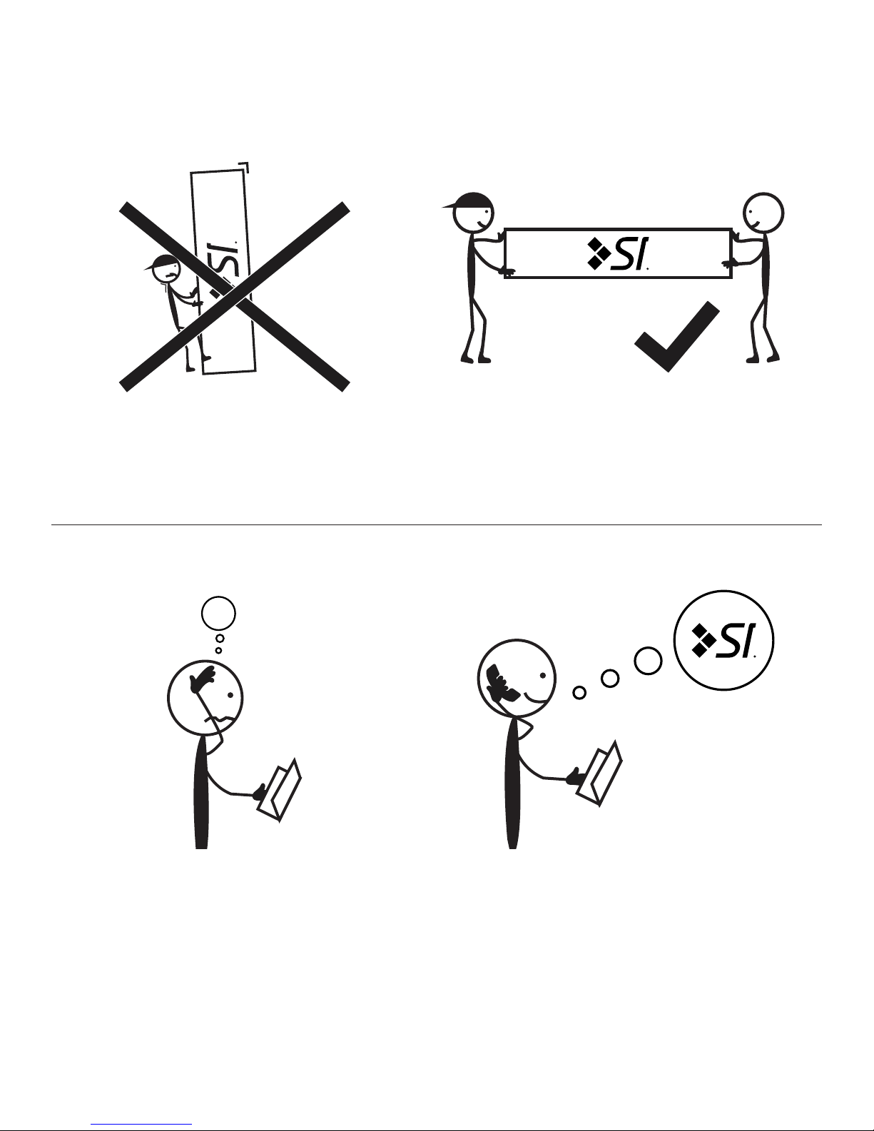
OPENING THE BOX � � � � � � � � � � � � � � � � � � � � � � � � � � � � � � � � � � � � � � � � � � � � � � � � � � � � � � � � � � � � � � � � � � � � � � � � � � � � � � � 7
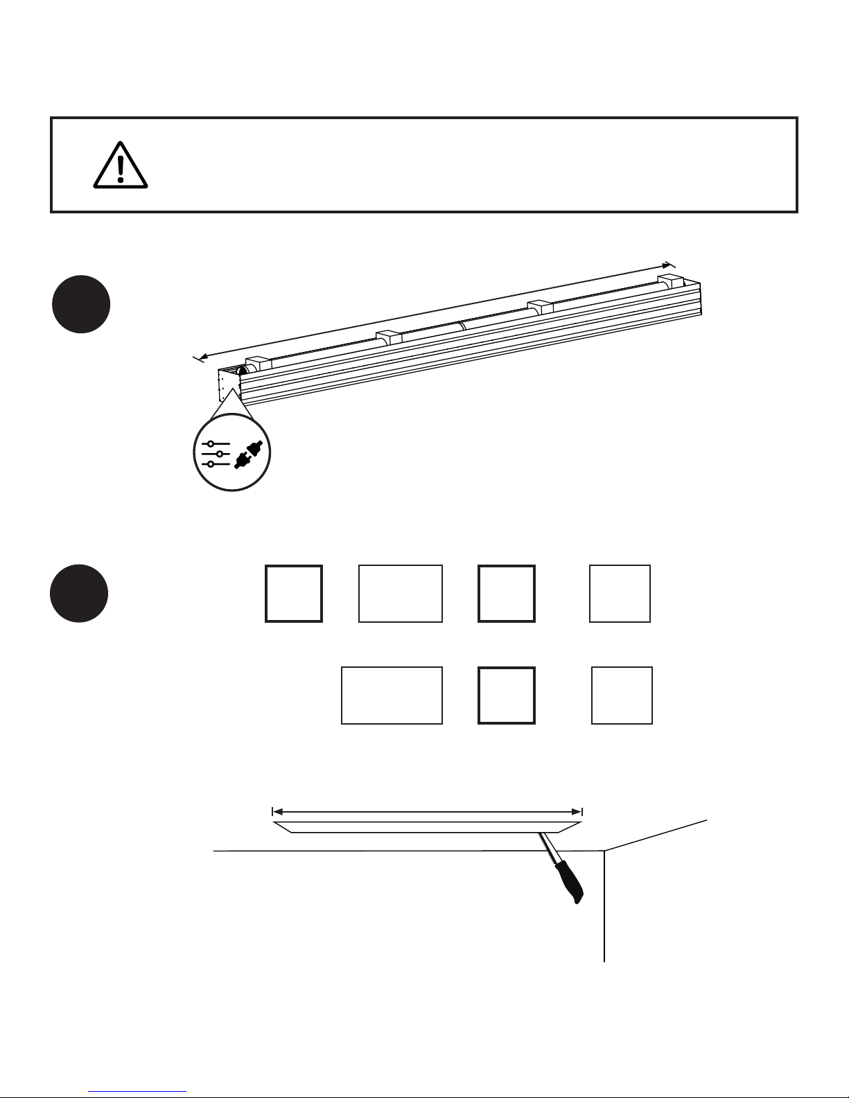
CEILING POCKET PREPARATION� � � � � � � � � � � � � � � � � � � � � � � � � � � � � � � � � � � � � � � � � � � � � � � � � � � � � � � � � � � � � � � � � � � � 8
INSTALLATION TYPE� � � � � � � � � � � � � � � � � � � � � � � � � � � � � � � � � � � � � � � � � � � � � � � � � � � � � � � � � � � � � � � � � � � � � � � � � � � � � � 9
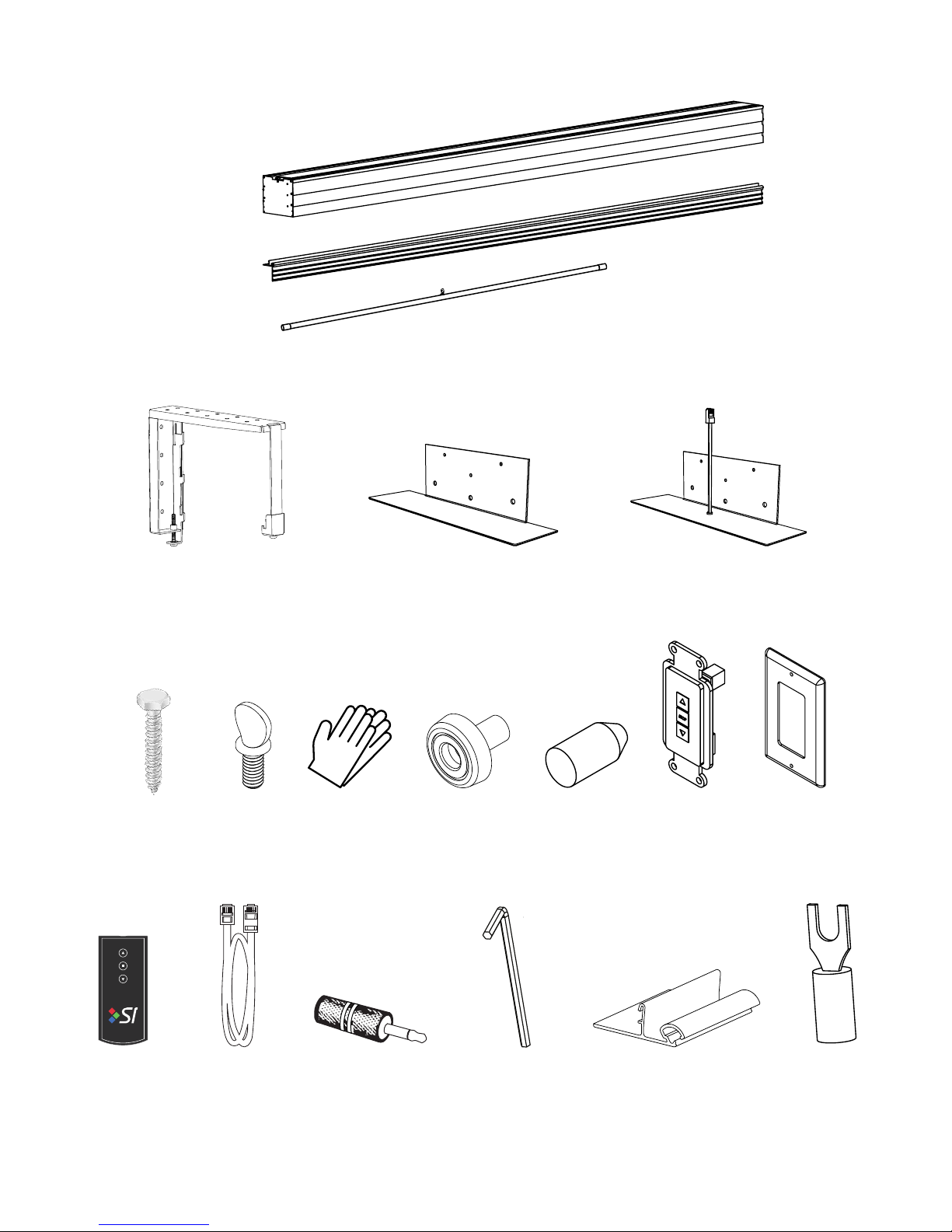
L-BRACKET PARTS LIST � � � � � � � � � � � � � � � � � � � � � � � � � � � � � � � � � � � � � � � � � � � � � � � � � � � � � � � � � � � � � � � � � � � � � � � � � � � � � � � � � 10
L-BRACKET INSTALLATION � � � � � � � � � � � � � � � � � � � � � � � � � � � � � � � � � � � � � � � � � � � � � � � � � � � � � � � � � � � � � � � � � � � � � � � � � � � � � � 11
L-BRACKET POWER AND CONTROLS� � � � � � � � � � � � � � � � � � � � � � � � � � � � � � � � � � � � � � � � � � � � � � � � � � � � � � � � � � � � � � � � � � � � � � 12
L-BRACKET CASE INSTALLATION� � � � � � � � � � � � � � � � � � � � � � � � � � � � � � � � � � � � � � � � � � � � � � � � � � � � � � � � � � � � � � � � � � � � � � � � � 13
SUSPENDED CEILING PARTS LIST � � � � � � � � � � � � � � � � � � � � � � � � � � � � � � � � � � � � � � � � � � � � � � � � � � � � � � � � � � � � � � � � � � � � � � � � 14
SUSPENDED CEILING PREPARATION� � � � � � � � � � � � � � � � � � � � � � � � � � � � � � � � � � � � � � � � � � � � � � � � � � � � � � � � � � � � � � � � � � � � � � 15
SUSPENDED CEILING POWER AND CONTROLS � � � � � � � � � � � � � � � � � � � � � � � � � � � � � � � � � � � � � � � � � � � � � � � � � � � � � � � � � � � � � 16
SUSPENDED CEILING CASE INSTALLATION � � � � � � � � � � � � � � � � � � � � � � � � � � � � � � � � � � � � � � � � � � � � � � � � � � � � � � � � � � � � � � � � 17
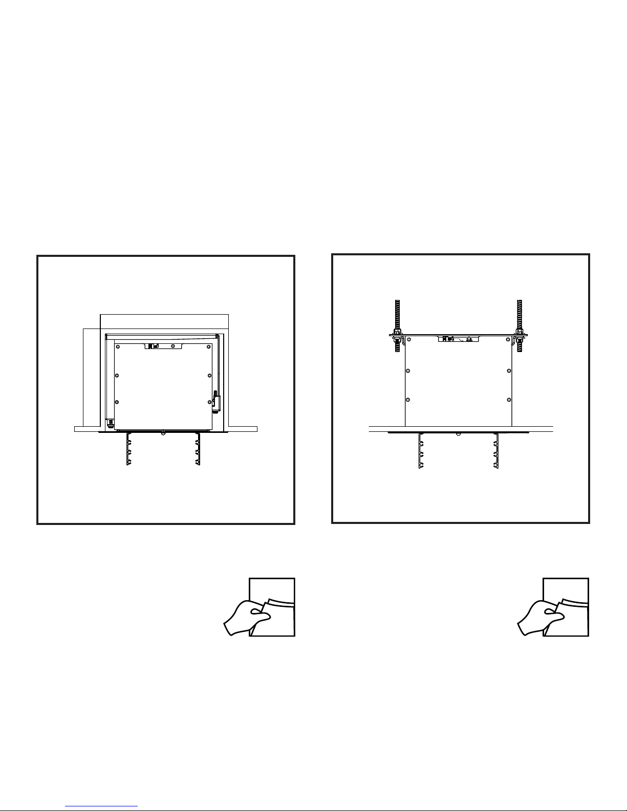
FLUSH CASE TO CEILING � � � � � � � � � � � � � � � � � � � � � � � � � � � � � � � � � � � � � � � � � � � � � � � � � � � � � � � � � � � � � � � � � � � � � � � � � 18
POWER AND CONTROLS� � � � � � � � � � � � � � � � � � � � � � � � � � � � � � � � � � � � � � � � � � � � � � � � � � � � � � � � � � � � � � � � � � � � � � � � � � 20
LOW VOLTAGE TRIGGER (OPTIONAL)� � � � � � � � � � � � � � � � � � � � � � � � � � � � � � � � � � � � � � � � � � � � � � � � � � � � � � � � � � � � � � � � � � � � � � 23
WALL SWITCH � � � � � � � � � � � � � � � � � � � � � � � � � � � � � � � � � � � � � � � � � � � � � � � � � � � � � � � � � � � � � � � � � � � � � � � � � � � � � � � � � � � � � � � � � 23
IR REMOTE (OPTIONAL)� � � � � � � � � � � � � � � � � � � � � � � � � � � � � � � � � � � � � � � � � � � � � � � � � � � � � � � � � � � � � � � � � � � � � � � � � � � � � � � � � 24
3RD PARTY CONTROL (OPTIONAL)� � � � � � � � � � � � � � � � � � � � � � � � � � � � � � � � � � � � � � � � � � � � � � � � � � � � � � � � � � � � � � � � � � � � � � � � 25
SETTING THE DROP � � � � � � � � � � � � � � � � � � � � � � � � � � � � � � � � � � � � � � � � � � � � � � � � � � � � � � � � � � � � � � � � � � � � � � � � � � � � � 27
WALL SWITCH GENERAL OPERATION � � � � � � � � � � � � � � � � � � � � � � � � � � � � � � � � � � � � � � � � � � � � � � � � � � � � � � � � � � � � � � � � � � � � � 30
INSTALL RIGHT SIDE END TRIM � � � � � � � � � � � � � � � � � � � � � � � � � � � � � � � � � � � � � � � � � � � � � � � � � � � � � � � � � � � � � � � � � � � 35
INSTALL DOORS� � � � � � � � � � � � � � � � � � � � � � � � � � � � � � � � � � � � � � � � � � � � � � � � � � � � � � � � � � � � � � � � � � � � � � � � � � � � � � � � � 36
REMOVING PACKAGING � � � � � � � � � � � � � � � � � � � � � � � � � � � � � � � � � � � � � � � � � � � � � � � � � � � � � � � � � � � � � � � � � � � � � � � � � � 38
SETTING THE LOWER LIMIT� � � � � � � � � � � � � � � � � � � � � � � � � � � � � � � � � � � � � � � � � � � � � � � � � � � � � � � � � � � � � � � � � � � � � � � 40
INSTALL LEFT SIDE END TRIM � � � � � � � � � � � � � � � � � � � � � � � � � � � � � � � � � � � � � � � � � � � � � � � � � � � � � � � � � � � � � � � � � � � � 41
INSTALL DOOR BUMPERS � � � � � � � � � � � � � � � � � � � � � � � � � � � � � � � � � � � � � � � � � � � � � � � � � � � � � � � � � � � � � � � � � � � � � � � � 42
ADJUSTING SCREEN TENSION � � � � � � � � � � � � � � � � � � � � � � � � � � � � � � � � � � � � � � � � � � � � � � � � � � � � � � � � � � � � � � � � � � � � 43
RAISING THE VIEWING AREA (IF NECESARRY)� � � � � � � � � � � � � � � � � � � � � � � � � � � � � � � � � � � � � � � � � � � � � � � � � � � � � � � 44
LOWERING THE VIEWING AREA (IF NECESARRY) � � � � � � � � � � � � � � � � � � � � � � � � � � � � � � � � � � � � � � � � � � � � � � � � � � � � 49
SCREEN MATERIAL CLEANING INSTRUCTIONS � � � � � � � � � � � � � � � � � � � � � � � � � � � � � � � � � � � � � � � � � � � � � � � � � � � � � � 54
TROUBLESHOOTING � � � � � � � � � � � � � � � � � � � � � � � � � � � � � � � � � � � � � � � � � � � � � � � � � � � � � � � � � � � � � � � � � � � � � � � � � � � � � 55
LIFETIME REPLACEMENT POLICY � � � � � � � � � � � � � � � � � � � � � � � � � � � � � � � � � � � � � � � � � � � � � � � � � � � � � � � � � � � � � � � � � 56

112216ZGFL
ZERO-G
5
11°
11°
SCREEN
Better
Best
Good
36”-42”
(91cm - 106cm)
PROJECTOR PLACEMENT

ZERO-G
6
BEFORE PROCEEDING
INSTALLER:
• Blocking is required. The ceiling or wall used for xture
installation must be able to support 300 lbs or more.
Failure to properly secure the screen may result in
injury and/or damage.
• Electrical work should be performed using appropriate
electrical codes and regulation, by a licensed electrical
professional.
• Before running cables in walls or ceilings see controls
section on pages 22,23 and 25 for control cable
requirements.
• Before removing the screen from the box, check for
damage and to make sure all parts are included.
• Do not use any sharp blades when opening the screen
packaging. Open by hand.
• Do not pull on the sides, crease, or fold the screen. The
screen material is very delicate.
• Care in mounting and correct operation will result in
long and satisfactory service from the SI screen.
• The screen should be level when installed. Always use
a carpenter’s level.
• Nothing should be fastened to any part of the screen
assembly.
NOTE: The screen has been thoroughly inspected and
tested at factory and found to be operating properly prior to
shipment.
END USER:
• To prevent damage, the operating and maintenance
of the screen should be performed by experienced
professionals.
• This is a nished product. Do not write or draw on the
surface.
• Do not put anything near or under the screen that
would come in contact or impede the normal
operation of the screen when deployed.
• Damage to the screen can result if an object prevents
the screen from fully deploying.
CAUTION: READ THE INSTRUCTIONS IN THEIR ENTIRETY BEFORE
PROCEEDING. ACTIONS CONTRARY TO THE INSTRUCTIONS INVALIDATE
THE WARRANTY AND MAY RESULT IN SERIOUS DAMAGE AND/OR INJURY.

112216ZGFL
ZERO-G
7
Do not remove the foam or packaging inside the cassette at
this time. Cut the straps to open the box, then remove the trim
pieces, doors assemblies, and mounting brackets and set all of
them out of the way of the installation area. Tear away the foam
from the top of the case but leave the foam inside the case.
OPENING THE BOX

ZERO-G
8
1
F
Measure the full length of the case (F)
2
Z
Cut a hole in the ceiling using the Zand Wvalues
from the formula above.
CEILING POCKET PREPARATION
BLOCKING REQUIRED. THE CEILING OR WALL USED FOR FIXTURE INSTALLATION
MUST BE ABLE TO SUPPORT 300 LBS OR MORE. FAILURE TO PROPERLY SECURE
THE SCREEN MAY RESULT IN INJURY AND/OR DAMAGE.
F+1½”+/- ¼”
=Z
CASE LENGTH TOLERANCE
LENGTH
OF OPENING
CLEARANCE
+/- ¼”
12½”
TOLERANCE
=W
DEPTH
OF OPENING
W

112216ZGFL
ZERO-G
9
10 14
L Bracket
Turn to page
INSTALLATION TYPE
Turn to page
Suspended Ceiling

ZERO-G
10
1X
2X
5X
1X
Idler Side
2X1X
1X 6X 1X 1X
L-BRACKET PARTS LIST
1X 1X
6X
1X
2X - 3X
16X - 24X
2X
1X
Motor Side
4X

112216ZGFL
ZERO-G
11
12 1/4''
1/4''
10''
to
10 1/2''
Ceiling
2” - 18”
(5 cm - 45.7 cm)
2” - 18”
(5 cm - 45.7 cm)
1
300 lbs
(136 kg)
Z
L-BRACKET INSTALLATION
OR
FAILURE TO PROPERLY LEVEL THE MOUNTING BRACKETS MAY CREATE ISSUES
WITH THE SCREEN OVER TIME, WHICH COULD DAMAGE THE SCREEN MATERIAL.
Install the brackets so that they will be 2” - 18” away from the edge
of the case on both sides. The ideal range is 2” - 4”.
Level the brackets to within ⅛” over 10’ using the case length (F); as
well as ½”over 1’ using the depth (W) of the pocket.

ZERO-G
12
L-BRACKET POWER AND CONTROLS
Controls In
Pass the control and power cables through the appropriate
openings in the case.
AC Power In
2
DO NOT OPEN THE CONTROL CENTER
WITH THE CIRCUIT BREAKER ON.

112216ZGFL
ZERO-G
13
Make sure bracket screws are backed out all the way before
putting the screen in place. Hook the bracket into all 4 grooves
in the case. You may need to raise the case by tightening the
screw on the back 3 hooks to hook in the front hook.
L-BRACKET CASE INSTALLATION
18
Turn to page
3
3+ INSTALLATION REQUIRES THREE OR MORE PEOPLE. THE PRODUCT WEIGHS
UP TO 225 LBS. PLEASE USE SAFE LIFTING AND RIGGING TECHNIQUES.

ZERO-G
14
SUSPENDED CEILING PARTS LIST
Threaded Rod 3/8’’ Minimum Nut Washer Washer Nut
Parts to be supplied by installer
1X
2X
5X
2X1X 1X
6X1X 1X
1X 1X
6X
1X 2X to 3X
2X
1X
Idler Side
1X
Motor Side
4X

112216ZGFL
ZERO-G
15
Hook the suspended ceiling brackets into the case as shown.
Position along the length of the case such that the large holes
will line up with the threaded rods, and lock down.
Secure 4 threaded rods to structural supports above the
installation location as shown.
Stuctural Member
Ceiling
4” - 20”
(10.16 cm - 50.8 cm) 4” - 20”
(10.16 cm - 50.8 cm)
Z
300 lbs
(90gk)
SUSPENDED CEILING PREPARATION
1
2
FAILURE TO PROPERLY LEVEL THE MOUNTING BRACKETS WILL CREATE ISSUES
WITH THE SCREEN OVER TIME, DAMAGING THE SCREEN MATERIAL.
2X to 3X

ZERO-G
16
SUSPENDED CEILING POWER AND CONTROLS
DO NOT OPEN THE CONTROL CENTER
WITH THE CIRCUIT BREAKER ON.
Controls In
Pass the control and power cables through the appropriate
openings in the case.
AC Power In
3

112216ZGFL
ZERO-G
17
Nut
Threaded Rod
Minimum 3/8’’
Nut
Washer
Washer
Supplied By
Installer
11 1/2 “ Approx
Lift the case up to the threaded rods and secure it in place
with the installer provided nuts and washers.
SUSPENDED CEILING CASE INSTALLATION
4
3+ INSTALLATION REQUIRES THREE OR MORE PEOPLE. THE PRODUCT WEIGHS
UP TO 225 LBS. PLEASE USE SAFE LIFTING AND RIGGING TECHNIQUES.

ZERO-G
18
FLUSH CASE TO CEILING
Hook the short trim piece into the case to use as a reference
for the following step (2).
1

112216ZGFL
ZERO-G
19
Flush suspended
Raise the case up until the reference trim piece is flush with the ceiling.
Repeat this at the front and back of all mounting brackets.
Level the case to within ⅛” over 10’ using the case length (F); as well as
½”over 1’ using the depth (W) of the pocket.
Flush L Bracket
2
FLUSH CASE TO CEILING

ZERO-G
20
POWER AND CONTROLS
1
Open the tray.
Carefully unscrew and pull down the control center ensuring
none of the cables or motherboard become damaged. If you
feel resistance do not yank.
DO NOT OPEN THE CONTROL CENTER
WITH THE CIRCUIT BREAKER ON.
Other manuals for Zero-G
1
Table of contents
Other Screen Innovations Projector Accessories manuals
Popular Projector Accessories manuals by other brands

Prijector
Prijector PR-N101+ user guide

Accessory Power
Accessory Power USA GEAR PRO Series user guide

XLT Systems
XLT Systems XCU 190 installation instructions

Premier Mounts
Premier Mounts CPD10WALLARM installation instructions

AMX
AMX NMX-MM-1000 quick start guide

CHIEF
CHIEF Cable Lock Kit LC-1 installation instructions

peerless-AV
peerless-AV ACC 912 Installation and assembly

Mitsubishi Electric
Mitsubishi Electric OL-X500SZ Specifications

Elite Screens
Elite Screens CineGrey 5D Care and use

Pyle
Pyle PRJSM7206 user manual

Draper
Draper AeroLift 35 Installation & operating instructions

AllSportSystems
AllSportSystems SkyRail Plus installation guide