ScreenBeam 1100 Plus User manual

ScreenBeam 1100
Plus
Wireless Display
Receiver
Firmware 11.1.8.0
User Manual
V1.1
For Catalog # SBWD1100P

Table of Contents
Part I
Getting Started ...................................................................................................................... 1
I.1
Contents in the Box ....................................................................................................... 1
I.2
Meeting ScreenBeam 1100 Plus ................................................................................... 1
I.2.1
ScreenBeam 1100 Plus .......................................................................................... 2
I.3
Minimum Requirements ............................................................................................... 2
I.3.1
S stem Requirements............................................................................................ 2
I.3.2
Network Requirements ......................................................................................... 2
I.3.3
Setup Requirements .............................................................................................. 3
Part II
Installing the Receiver ........................................................................................................... 4
II.1
Setting up ScreenBeam 1100 Plus Receiver .................................................................. 4
II.2
Connecting the Receiver to a Network ......................................................................... 6
II.2.1
Wired Connection ................................................................................................. 6
II.2.2
Wireless Connection ............................................................................................. 8
II.2.3
Dual-network Connection ................................................................................... 11
Part III
Connecting Client Device .................................................................................................... 12
III.1
Overview of Wireless Displa Network Modes ........................................................... 12
III.1.1
Local Wi-Fi ........................................................................................................... 12
III.1.2
Wi-Fi Miracast ..................................................................................................... 13
III.1.3
Wireless Displa over existing LAN...................................................................... 13
III.2
Connect using Local Wi-Fi ........................................................................................... 14
III.3
Connect using Wi-Fi Miracast...................................................................................... 20
III.4
Connect using Existing Wireless Network or LAN ....................................................... 24
III.5
Displa ing with a connected HDMI cable .................................................................... 30
Part IV
Displa and Control Options ............................................................................................... 31
IV.1
Projection Mode ......................................................................................................... 31
IV.2
HDMI Output Behaviors .............................................................................................. 32
IV.2.1
Single Mode ........................................................................................................ 32
IV.2.2
Quick Switch Mode ............................................................................................. 33
IV.2.3
Multiview Mode .................................................................................................. 34
IV.3
USB over Network Control .......................................................................................... 34
IV.4
Using Interactive Touch Displa .................................................................................. 35
IV.4.1
S stem Requirements.......................................................................................... 35
IV.4.2
Setup Requirements ............................................................................................ 35
IV.4.3
Supported Features ............................................................................................. 36
IV.4.4
Setup and Instructions ........................................................................................ 36
IV.4.5
Ghost Inking™ ..................................................................................................... 37
Part V
Device Management for IT Administrator........................................................................... 38
V.1
Using ScreenBeam CMS Software ............................................................................... 38
V.2
Using Local Management on ScreenBeam .................................................................. 38
V.2.1
Method 1: ScreenBeam Local Wi-Fi Network ..................................................... 39
V.2.2
Method 2: Network Connection via DHCP .......................................................... 41

V.2.3
Method 3: Wireless P2P Direct Connection ........................................................ 42
V.3
Configuring ScreenBeam ............................................................................................. 42
V.3.1
General Settings .................................................................................................. 42
V.3.1.1
Renaming the Receiver ....................................................................... 42
V.3.1.2
Setting up the Login Username and Password .................................... 43
V.3.1.3
Setting up the Receiver’s Displa Language ........................................ 44
V.3.1.4
Modif ing the Receiver’s Host Name .................................................. 45
V.3.1.5
Setting up Time Zone .......................................................................... 45
V.3.2
Setting up Wireless Displa Mode ....................................................................... 46
V.3.3
Wireless Displa over LAN ................................................................................... 47
V.3.3.1
Setting up Wireless Displa over LAN for Windows 10 Devices .......... 47
V.3.3.2
Setting up Native Screen Mirroring for macOS/iOS Devices ............... 48
V.3.3.3
Setting up Wireless Displa over LAN for Chrome OS Device and Device
with Chrome Browser ................................................................................................. 50
V.3.4
P2P Wireless Settings .......................................................................................... 51
V.3.4.1
Setting up Miracast Connection .......................................................... 51
V.3.4.2
Setting up P2P Operating Channel ...................................................... 52
V.3.4.3
Setting up Transmit Power .................................................................. 53
V.3.5
Securit Settings .................................................................................................. 55
V.3.5.1
Setting up PIN Pairing Method ............................................................ 55
V.3.6
Displa Settings ................................................................................................... 58
V.3.6.1
Setting up Displa Sharing Mode ........................................................ 58
V.3.6.2
Setting up Receiver Name Displa for Quick Switch ........................... 59
V.3.6.3
Setting up Information Displa on RTC Screen .................................... 60
V.3.6.4
Managing HDMI/VGA Port Output ...................................................... 63
V.3.6.5
Waking up the Receiver....................................................................... 64
V.3.6.6
Adjusting TV Screen Size ..................................................................... 65
V.3.6.7
Updating the Receiver’s Background Image ....................................... 66
V.3.6.8
Updating the Receiver’s Screen Saver Image ...................................... 67
V.3.7
Digital Signage Settings ....................................................................................... 69
V.3.8
Network Settings ................................................................................................. 70
V.3.8.1
Setting up Local Wi-Fi Network Mode ................................................ 70
V.3.8.2
Setting up an Interface for CMS Connection ....................................... 71
V.3.8.3
Setting up an Internet WAN Interface ................................................. 72
V.3.8.4
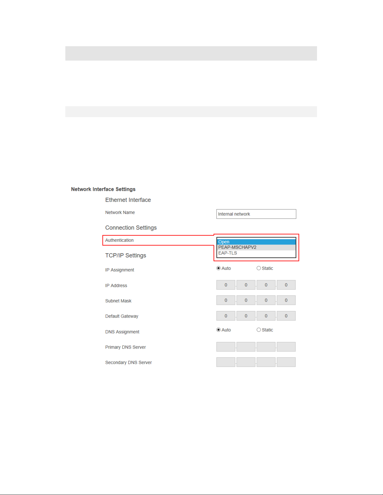
Renaming Ethernet Interface’s Network Name .................................. 73
V.3.8.5
Setting up the Receiver’s IP Address ................................................... 73
V.3.8.6
Specif ing a DNS Server for the Receiver ............................................ 74
V.3.9
Local Wi-Fi Settings ............................................................................................. 76
V.3.10
Receiver Management Access Settings ............................................................... 77
V.3.10.1
Specif ing ScreenBeam CMS for the Receiver .................................... 77
V.3.10.2
Specif ing a Port for the Receiver’s LMI .............................................. 78
V.3.10.3
Setting up Local Management Interface Access .................................. 79
Part VI
Updating Firmware for the Receiver ................................................................................... 81
VI.1
Firmware Update via LMI ............................................................................................ 81

VI.1.1
Updating Firmware from a Local PC .................................................................... 81
VI.1.2
Updating Firmware from the Internet ................................................................ 83
VI.2
Firmware Update using a USB Flash Drive .................................................................. 85
Part VII
Receiver Maintenance ................................................................................................ 86
VII.1
Setting up Receiver Logging ........................................................................................ 86
VII.2
Exporting Receiver Log with LMI ................................................................................. 87
VII.3
Disabling the Reset Button .......................................................................................... 88
VII.4
Viewing S stem Uptime .............................................................................................. 88
VII.5
Rebooting the Receiver ............................................................................................... 89
VII.6
Resetting the Receiver to Default ............................................................................... 89
VII.7
Tips for Optimal Performance ..................................................................................... 91
Appendix I
Troubleshooting and FAQs .......................................................................................... 92
Troubleshooting .......................................................................................................................... 92
FAQs ............................................................................................................................................ 94
Appendix II
Notices ........................................................................................................................ 97
Warrant ..................................................................................................................................... 97
GPL Info ....................................................................................................................................... 97
Technical Support ........................................................................................................................ 97
FCC Warning ................................................................................................................................ 98
CE Statement ............................................................................................................................... 99
TELEC Statement ....................................................................................................................... 103

1
Part I Getting Started
Thank you for your purchase of ScreenBeam 1100 Plus Wireless Display Receiver
(hereinafter refer to as “ScreenBeam 1100 Plus”).
ScreenBeam 1100 Plus wireless display receiver enables native screen mirroring from your
Windows, Android, Apple, and Chromebook devices - without apps or wires. ScreenBeam
1100 Plus lets you wirelessly stream what’s on your wireless display capable device to your
HDTV, including movies, videos, photos, music, and more. The receiver frees your eyes from
a tiny screen.
The receiver boasts some great features, including fast connect, quick switch, multi-network
support, multi-view support, digital signage, enhanced security, IT manageability, smooth
video playback, 4K HDMI output, ultra-low delay, Windows 10 optimization, versatile
compatibility, low power consumption, and more.
For optimal wireless display experience, we strongly recommend you update your receiver
to the latest firmware. Check firmware update now on https://support.screenbeam.com.
I.1 Contents in the Box
Contents in the receiver’s package are listed below:
ScreenBeam 1100 Plus wireless display receiver (1)
HDMI
®
Cable (1)
AC Power Adapter (1)
Magnetic Mounting Kit (1)
Product documentation
I.2 Meeting ScreenBeam 1100 Plus
This manual is applicable to the following catalog #s:
SBWD1100P

2
I.2.1 ScreenBeam 1100 Plus
Power Input (12V/3A), for power supply
USB ports, (two USB 2.0 ports and one USB 3.0 port), for provisioning CMS connection
data, firmware update, connecting to touch display, and USB over network control (UIBC)
Ethernet Port (ETHERNET), for receiver management with ScreenBeam Central
Management System (CMS) / Local Management Interface (LMI) or for multi-media
streaming over infrastructure network
HDMI Output (HDMI OUT), for connecting to HDTV/projector with an HDMI port for video
and audio output
HDMI Input (HDMI IN), for connecting to an HDMI source for video input
Audio Output (AUDIO), for outputting audio to speaker
Power Indicator, indicating power supply status
Reset button, for resetting the receiver to default settings
I.3 Minimum Requirements
System requirements for ScreenBeam 1100 Plus are shown below:
I.3.1 System Requirements
Client device from 2015 or newer with one of the following operating systems:
Windows 10 build 1709 (and later)
macOS X 10.10 (and later)
iOS 9 (and later)
Android 4.4 (and later) with Miracast
Chrome OS 74.0.3729.159 (and later) with Cast
I.3.2 Network Requirements
For wireless display over the existing wireless network or LAN:
Ethernet: 100BASE-T 10/100 connection (1 Gbps is recommended)
Wireless: 802.11ac (5 GHz is strongly recommended)

3
Multicast DNS (mDNS) support is required for auto-discovery of ScreenBeam
Required ports
•
5353 (UDP) for Multicast DNS (mDNS) discovery
•
7100 (TCP) for macOS, iOS and Windows 10 mirroring
•
7250 (TCP) for Miracast over LAN data stream
•
47000 (TCP) for Airtunes in AirPlay
•
18000-18009 (TCP) for macOS and iOS AV data
Note: Additional network configuration is not required for Wi-Fi Miracast enabled device to
connect. Verify Group Policy and firewall settings allow Wi-Fi Direct groups or hosted
networks.
I.3.3 Setup Requirements
ScreenBeam 1100 Plus receiver
Display with an available HDMI input
(Optional) Touchscreen with USB touch cable
An Ethernet network connection with DHCP IP or a Wi-Fi router
Note: This is used for wireless display over LAN and management.

4
Part II Installing the Receiver
This chapter explains how to connect ScreenBeam 1100 Plus to a display such as an HDTV
or projector. Make sure you have all the contents from the receiver’s package available
before starting.
II.1 Setting up ScreenBeam 1100 Plus Receiver
It is quite easy and fast to set up the receiver. You can easily complete the setup by your own.
To connect ScreenBeam 1100 Plus to an HDTV:
1. Get the receiver, AC power adapter, and HDMI cable from the receiver’s package, and
place the receiver next to the display.
2. Plug one end of the HDMI cable into the HDMI OUT port on the receiver, and the other
end into an available HDMI port on the display.
3. (Optional) If the display has USB HID touch capability, insert the HID USB connector
into a USB port on the ScreenBeam receiver. (USB cable is not included).
4. (Optional) Connect one end of the Ethernet cable to the receiver’s Ethernet port and
connect the other end to the network switch with DHCP IP. (Ethernet cable is not
included).
Note: Refer to Section II.2 for more information on setting up a network connection.
5. Plug the connector of the power cord to the receiver’s power input port labeled “12V/3A”,
and plug the power adapter to a power outlet.
When the above steps are complete, the hardware should be connected as shown in
the figure below:
Note: Power adapter may vary in different region.
6. Turn on the display and set it to display the input from the correct HDMI port (the one
you have plugged into in Step 2).
7. Verify that the “Wireless Display Ready to Connect” screen appears on the display.

5
The receiver is connected to the display, and it is ready for use.
ScreenBeam 1100 Plus receiver includes an HDMI Input to accommodate either wireless or
wired connection. If there is an existing HDMI cable connected to the display for wired
projection, it can be used in conjunction with ScreenBeam in case the client device cannot
connect wirelessly.
1. Remove the existing HDMI cable from the display’s HDMI port.
2. Connect the existing HDMI cable to the HDMI IN port on the receiver.
3. Connect the provided HDMI cable from the HDMI OUT of the receiver to the display.
4. Refer to Section IV.2 to manage the HDMI output behavior.

6
II.2 Connecting the Receiver to a Network
ScreenBeam 1100 Plus receiver supports both wired and wireless connections. You can
deploy ScreenBeam 1100 Plus receivers based on your network requirements.
Note: The setups in this section are optional.
II.2.1 Wired Connection
ScreenBeam 1100 Plus receiver provides a built-in Ethernet port, allowing direct connection
to an Ethernet network.
To connect the receiver to an Ethernet network, follow this procedure:
1. (Optional) If you are going to connect your receiver to your network with RADIUS
authentication, you need to configure authentication parameters through LMI > Network
Settings > Network Interface Settings > Ethernet Interface > Connection Settings.
When Authentication is set to PEAP/MSCHAPV2,
User Name: This is for authentication through a RADIUS server. It is RADIUS
account User Name.
Password: It is RADIUS account password.
When Authentication is set to EAP-TLS, the following items are available:

7
User Name: It is the User Principal Name or RADIUS Identity (if necessary).
Note: The User Name supports these characters: a-z, A-Z, 0-9, @, ., and _.
Password: It is the password of the Private Key.
System Date & Time: It is used to set date and time for the receiver. Users should
set the date and time according to the validity period of the certificates.
CA Certificate: It is the root certificate. Click the Browse button to browse and add
the certificate.
User Certificate: It is the user certificate. Click the Browse button to browse and
add the certificate.
Private Key: It is the user’s private key. Click the Browse button to browse and add
the certificate.
Validity Period: It displays the effective period of the certificates.
Note:
Currently, only certificates in “.pem” format are supported, and the certificates must
be generated using the “DER encoded binary X.509” method.
The length of the certificate file name must not exceed 64 bytes, and the file size
must be less than 100 KB.
All the three certificates are required for authentication.
Users should select the right certificate file for each type of certificate.
2. Connect your ScreenBeam receiver to your network with a quality Ethernet cable.
3. The receiver will be assigned an IP address after a few seconds, if a DHCP server is
available on your network.
Note: ScreenBeam receiver is set to obtain an IP address automatically by default. If
you want to set the receiver’s IP address or DNS server to static, consult your network
administrator.
Refer to Section V.2 Using Local Management on ScreenBeam for detail on how to log

8
into the receiver’s LMI.
Refer to Section V.3.8.5 Setting up the Receiver’s IP Address for detail on how to set
up the receiver’s IP address.
Refer to Section V.3.8.6 Specifying a D S Server for the Receiver for detail on how to
set up the receiver’s DNS server.
II.2.2 Wireless Connection
ScreenBeam 1100 Plus receiver provides a built-in WLAN adapter, which allows the receiver
to wirelessly connect to your network. It is required to set up the wireless connection
parameters before starting the connection.
To connect the receiver to a wireless network, follow this procedure:
1. Go to the receiver’s LMI, and set IP address assignment and DNS assignment to auto
in the TCP/IP Settings section.
Note:
If you want to set the receiver’s IP address or DNS server to static, consult your
network administrator.
Refer to Section V.2 Using Local Management on ScreenBeam for detail on how to log
into the receiver’s LMI.
Refer to Section V.3.8.5 Setting up the Receiver’s IP Address for detail on how to set
up the receiver’s IP address.
Refer to Section V.3.8.6 Specifying a D S Server for the Receiver for detail on how to
set up the receiver’s DNS server.
2. Go to LMI > Network Settings > Network Interface Settings > Wireless Interface

9
Connection Settings, and configure the parameters according to specific requirements.
Network Name: The SSID of the wireless router (AP).
Security Type: Select a security type, the one you have selected on your wireless
router. Available security types are Open, Shared, WPA-PSK[TKIP], WPA2-
PSK[AES], WPA-PSK[TKIP]+WPA2-PSK[AES], PEAP/MSCHAPV2, and EAP-
TLS.
When Security Type is set to Shared, WPA-PSK[TKIP], WPA2-PSK[AES], or WPA-
PSK[TKIP]+WPA2-PSK[AES],
User Name: Not used.
Password: The pre-shared password for the wireless SSID.
When Security Type is set to PEAP/MSCHAPV2,
User Name: This is for authentication through a RADIUS server. It is RADIUS
account User Name.
Password: It is RADIUS account password.
When Security Type is set to EAP-TLS, the following items are available:
User Name: It is the User Principal Name or RADIUS Identity (if necessary).
Note: The User Name supports these characters: a-z, A-Z, 0-9, @, ., and _.
Password: It is the password of the Private Key.
System Date & Time: It is used to set date and time for the receiver. Users should
set the date and time according to the validity period of the certificates.

10
CA Certificate: It is the root certificate. Click the Browse button to browse and add
the certificate.
User Certificate: It is the user certificate. Click the Browse button to browse and
add the certificate.
Private Key: It is the user’s private key. Click the Browse button to browse and add
the certificate.
Validity Period: It displays the effective period of the certificates.
Note:
Currently, only certificates in “.pem” format are supported, and the certificates must
be generated using the “DER encoded binary X.509” method.
The length of the certificate file name must not exceed 64 bytes, and the file size
must be less than 100 KB.
All the three certificates are required for authentication.
Users should select the right certificate file for each type of certificate.
3. Click the Connect button to connect the receiver to your network. The adapter will
connect to the wireless router (AP) in a few seconds.
Note:
The WLAN adapter will connect to your network when the receiver is in Wireless
Display Ready to Connect state.
The WLAN adapter may take some time to connect to your network, depending on
your network environment.

11
II.2.3 Dual-network Connection
ScreenBeam 1100 Plus can be connected to two different networks concurrently. This dual-
network feature allows the flexibility of supporting wireless display for either staff (on internal
network) or visitors (on guest network).
1. Plan your network in advance. For example, one for internal use, and one for guest use.
2. Connect ScreenBeam 1100 Plus to the internal network via Ethernet, and verify that an
IP address is assigned.
3. Connect ScreenBeam 1100 Plus to the guest network via wireless connection, and verify
that an IP address is assigned.
Now both the user that connects to the internal network and the user that connects to the
guest network can connect to ScreenBeam for wireless display.

12
Part III Connecting Client Device
This section provides the instructions on how to connect to ScreenBeam using the native
screen mirroring from the most common operating systems.
Refer to www.screenbeam.com/setup for details and instructions for common operating
systems.
Note: The web page will display instructions based on the client-device OS. Use the links at
the bottom of the web page to select OS-specific instructions.
III.1 Overview of Wireless Display Network Modes
The ScreenBeam 1100 Plus allows presenters with Windows 10, macOS, iOS, Android, or
Chromebook device to wirelessly display without requiring any apps. ScreenBeam 1100 Plus
offers a variety of secured network modes to support connection from internal users on
different subnets and external guest users. ScreenBeam 1100 Plus supports local Wi-Fi, Wi-
Fi Miracast, and wireless display over existing infrastructure network. Two or more modes
can operate concurrently to support various scenarios where both internal and guest users
could simply connect and project.
III.1.1 Local Wi-Fi
The ScreenBeam Wi-Fi mode provides the simplest form of network for client devices to
connect and project. In this mode, user needs to connect the client device Wi-Fi to the
ScreenBeam Wi-Fi and then select the receiver to mirror. This mode is ideal for guest client
devices that need wireless display and/or Internet access. Internet is available if the
ScreenBeam receiver is connected to the existing network, wired or wireless, and the
receiver’s local Wi-Fi is set to NAT or Bridge. Mobile device with cellular service can access
the Internet and wireless display if bridge mode is disabled.
Note: ScreenBeam Wi-Fi is fully secured and manageable via ScreenBeam CMS with
options to tune the wireless transmission power, channel and encryption type.

13
III.1.2 Wi-Fi Miracast
The Wi-Fi Miracast mode allows compatible Wi-Fi Miracast devices to connect directly to
ScreenBeam, even when connected to an infrastructure wireless network. Miracast is
commonly available on Windows 10/8.1 and Android 4.4 (and later) devices since 2015.
Users can enjoy wireless display and Internet access if the client device is already connected
to Wi-Fi.
III.1.3 Wireless Display over existing LAN
ScreenBeam 1100 Plus can be connected to the existing wireless and wired network and
supports wireless display for client devices on either network. This is a common setup to
support client devices that need access to network resources. Additional port and network
configurations may be required for this mode to work seamlessly.
ScreenBeam 1100 Plus can be connected to two different networks concurrently. This dual-
network feature allows the flexibility of supporting wireless display for either staff (on internal
network) or visitors (on guest network). Refer to the deployment guide for more details.

14
III.2 Connect using Local Wi-Fi
This section explains how to connect a client device to ScreenBeam 1100 Plus using the
local AP on ScreenBeam 1100 Plus.
1. Make sure that the Wireless display over LAN feature is enabled for Windows 10,
macOS/iOS AirPlay and/or Google Cast screen mirroring. Refer to section V.3.3 Wireless
Display over LA for detail.
Note: You can also configure your receiver with CMS.
2. Connect the client device’s Wi-Fi to the wireless network (AP SSID) as shown on the TV
display. And enter the password for the wireless network. By default, the password is
screenbeam (case-sensitive).
Note: For Windows 10/8.1 or Android devices with Miracast, you can skip to Section III.3
Connect using Wi-Fi Miracast.

15
3. Select the ScreenBeam receiver name as shown on the TV display.
For Windows 10
Select Connect from the Action Center by swipin from ri ht or simultaneously
pressin the Windows key and K.
Fi ure: Selectin receiver on Windows 10 device

16
For iOS or macOS
Connect with AirPlay from the menu bar or control center.
Figure: Selecting receiver on iOS device
Figure: Selecting receiver on macOS device
Other manuals for 1100 Plus
1
Table of contents
Other ScreenBeam Receiver manuals