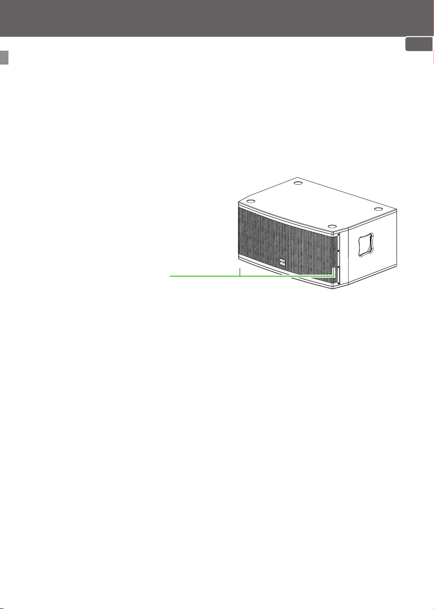
SE Audiotechnik C Series User manual

C6 SE
Self-powered
PA Subwoofer Extension
USER MANUAL
C-Line
EN

Copyright by SE Audiotechnik®2018. All rights reserved.
The content of this document is subject to change without prior notice to
improve reliability, function, design or otherwise.
Check our website for the latest digital version of this manual. If you
encounter any errors in this document, feel free to let us know.

speaker trade Inh. Michael von Keitz e.K.
Neuenhofer Str. 42–45
42657 Solingen Germany
Phone: +49 212 38226 - 10
Email: [email protected]
Web: www.se-audiotechnik.de
Speaker Electronic (Jia Shan) Co., Ltd.
No. 8 Development Zone Road
Huimin Sub-district, Jiashan County, Zhejiang, 314112, P.R. China
Phone: +86 400 109 1122
Email: [email protected]
Web: www.se-audiotechnik.com
Please read this user manual carefully, so you can make
optimum and troublefree use of your product. Keep this
document in a safe place and follow its instructions diligently.
When in use, this product is capable of producing high Sound
Pressure Levels (SPL) that can lead to irreversible hearing
damage to anyone.
CONTACT INFORMATION
Head Office
Asia Pacific Sales & Development Center
Noise level (dBA) 85 94 97 112 127
Max. recommended exposure
time per 24 hours 8 hrs. 1 hr. 30 min. 56 sec. 1 sec.
EN

4 5
TABLE OF CONTENTSTABLE OF CONTENTS
1 INTRODUCTION
1.1 How to use this manual 5
1.1.1 Symbol description 5
1.2 Safety instructions 6
1.2.1 Electricity 6
1.2.2 General 7
1.2.3 Setup & operation 7
1.3 Product overview 8
1.3.1 Package contents 8
1.3.2 Unboxing 8
1.3.3 Intended use 9
1.3.4 Main features 9
2 GETTING STARTED
2.1 Quick start guide 10
2.1.1 Precautions 10
2.1.2 Extension placement 11
2.2 User interface 11
2.2.1 Rear panel overview 11
2.3 Mono setup example 13
3 TECHNICAL INFORMATION
3.1 Specifications 14
3.1.1 Mechanical dimensions 15
EN

4 5
INTRODUCTION
How to use this manual
Symbol description
INTRODUCTION
Throughout this document you will
come across several symbols, which
indicate various types of information.
You can find each symbol and it‘s
meaning in the list below.
Especially on the product itself you
may see different types of labels.
Here you can look up their meanings.
Pay special attention.
Risk of electric shock.
Important operating or
maintenance instructions.
Earth/ground connection.
The equipment is for
indoor use only.
Compliance with
the low voltage and
electromagnetic
compatibility.
Helpful tips and
recommendations.
Possible hearing damage or
even loss.
An interdiction, which you
must follow.
This is okay.
Important information
Advice
Hearing damage
Prohibition
Confirmation You should not place the
item in the general waste.
Waste Electrical and
Electronic Equipment
Directive (WEEE Directive).
EN

6 7
INTRODUCTION
Electricity
This unit has been engineered and manufactured to
ensure your personal safety.
IMPROPER USE CAN RESULT IN POTENTIAL
ELECTRICAL SHOCK OR FIRE HAZARD.
Read the following precautions carefully and stick to
them in order to avoid the possibility of serious injury or even death from
electrical shock, short-circuiting, fire or other hazards.
These precautions include, but are not limited to, the following items:
Safety instructions
01. The power cord of the device is
equipped with an earthing contact, it must
be connected to an outlet with a protective
ground. Never disconnect the protective
ground of the power cord.
02. Always unwind cable reels completely
to prevent overheating or even fire hazards.
03. Do not expose this equipment to rain or
moisture, dripping or splashing liquids.
04. Objects filled with liquids, such
as vases, should not be placed on this
apparatus.
05.To reduce the risk of electric shock, do
not attempt to open or modify any part of
the unit. No user-serviceable parts inside.
Leave servicing to qualified personnel only.
06. Always disconnect the equipment
from the power outlet, if there is risk of a
lightning strike, or it‘s not being used for
longer periods of time.
07. To completely disconnect this
equipment from the AC mains, pull the
power cord plug from the AC outlet.
08. If your equipment has been damaged
and is no longer functioning properly,
switch it off immediately and unplug it from
the mains outlet.
09. Do not step on the power cord. Make
sure that the power cable does not become
kinked.
10. Never touch the power cord and power
adapter with wet hands.
EN

6 7
INTRODUCTION
Setup & operation
General
01. Please notice all the safety warnings.
Never remove safety warnings or other
information from the equipment.
02. Use the equipment only in the intended
manner and for the intended purpose.
03. Use this equipment only with the
accessories recommended and intended by
the manufacturer.
04. C6 and C6 SE are equipped with a
powerCON®mains connector, which is
locked by rotating it inside of the socket.
This also means that a person can trip over
the fixed power cord, which can lead to
personal injuries and/or other damage. For
this reason, always be careful when laying
cables.
05. Clean the equipment using a dry cloth.
06. Beware the comply with all applicable
disposal laws in your country. During
disposal of packaging, please separate
plastic and paper/cardboard.
07. Plastic bags must be kept out of
children‘s reach.
08. Never place inflammable items, e.g.
burning candles on the equipment.
09. Do not expose this equipment to
flammable materials, fluids or gases.
10. During operation or transport, make
sure that the equipment cannot fall down
and possibly cause property damage or
personal injuries.
Read these safety instructions carefully.
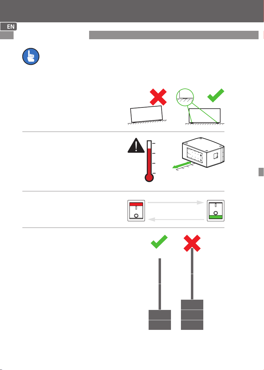
01. If the equipment has been exposed
to strong fluctuations in temperature (for
example, after transport), do not switch it
on immediately. Moisture and condensation
could damage the equipment.
02. This product is NOT intended to be
suspended on chains or ropes.
03. Do NOT use handles or other methods
to suspend the system, serious injuries
can be the result! Make sure that the
equipment is installed securely and cannot
fall down.
04. During installation, observe the
applicable safety regulations for your
country.
05. Never install or operate the equipment
near radiators, heat registers, ovens or
other sources of heat. Make sure that the
equipment is always installed so that it is
cooled sufficiently and cannot overheat.
06. Do not cover the metal panel at the
rear side of the subwoofer, as it serves as
a heat sink for the system amplifier. Keep
a minimum distance of 50 cm to any other
object for proper airflow.
EN

8 9
INTRODUCTION
Product overview
Package contents
Unboxing
1x
1x
1x
Manual
Power cable
Subwoofer extension
Please inspect your C6 SE packaging for any damage that may
have occurred during transport. If damage is found, notify
the transportation company immediately.
If you decide to keep the product though it’s packaging got
damaged upon transit, please check for any visual damage before
using it. Keep the shipping carton as evidence for inspection.
Contact your SE Audiotechnik dealer or support centre for help.
Save all packaging materials and full package contents if you
ever need to transport or resell the system.
AA
B
B
C
C
EN

8 9
INTRODUCTION
Main features
Intended use
Class-D amplification
2x 10” Subwoofers
LF 800/1200 W (RMS/peak)
Symmetric bass reflex
Professional plug and play PA subwoofer extension for indoor use with
modular structure. Designed to enhance the C6 column system, but can be
used with other 3rd party equipment as well. Ideal for medium sized venues
with a few hundreds of listeners.
EN

GETTING STARTED
10 11
The subwoofer of C6, as well as the
subwoofer extension C6 SE must be
placed on level ground, standing on
its rubber feet.
Ensure adequate cooling during
operation with a minimum distance
of 50 cm between the subwoofer’s
back panel and other objects such as
walls.
Always turn on the C6 system
last and turn it off first to avoid
damaging the speakers.
GETTING STARTED
Quick start guide
This guide briefly describes the main steps of extending your
C6 column system by the C6 SE.
Precautions
Temp.
POWER
POWER
Turn ON last
Turn OFF first
50 cm
Never assemble a C6 system with
other than the intended single
subwoofer extension.
EN

GETTING STARTED
10 11
Extension placement
Rear panel overview
C6 subwoofer
C6 SE
The ideal placement of your C6 SE subwoofer extension is right beneath the
C6 column system. This way the column system’s rubber feet perfectly fit the
recesses on top of the bass extension unit maintaining stability.
Depending on your application, you may also put the subwoofer extension to
either side of the C6 system.
User interface
CA B D
B
A
C
D
POWER SWITCH
PRODUCT SERIAL NUMBER
PRODUCT INFORMATION
POWER IN SOCKET
Tell this code to the customer
support, if you are in need of help.
(see “Symbol description” on
p.5)
Connect the powerCON® cable here
and twist it clockwise to lock.
C6SE
SUB
PHASE
0°
180°
PSSC IN
LINE IN
200-240V / 50-60 Hz
100-120V / 50-60 Hz
MAX 1000W
PROCESSED SUB
SLAVE CONTROL IN
LINE IN INEOUTL
PROTECT
LIMIT
SIGNAL
ON
POWER
SUB LEVE
L
MIN MAX
80Hz180Hz
LOW PASS
Turn the whole system on/off.
is ON and is OFF position.
EN

GETTING STARTED
12 13
C6SE
SUB
PHASE
0°
180°
PSSC IN
LINE IN
200-240V / 50-60 Hz
100-120V / 50-60 Hz
MAX 1000W
PROCESSED SUB
SLAVE CONTROL IN
LINE IN INEOUTL
PROTECT
LIMIT
SIGNAL
ON
POWER
SUB LEVE
L
MIN MAX
80Hz180Hz
LOW PASS
K
E
F
G
H
I
J
G
H
K
J
I
F
E
SUB PHASE TOGGLE
LINE IN (XLR)
COMBO LINE OUT (XLR/6,35 mm)
SUB LEVEL ROTARY KNOB
LOW PASS ROTARY KNOB
DSP MODE TOGGLE
MAIN INDICATORS
Toggle the phase between 0° & 180°
to match phase response with eg.
other 3rd party equipment. (see
“DSP MODE TOGGLE” on p.12)
Connect to either C6 system’s
processed output “To C6 SE”, or to
any line level audio source here.
Connect another C6 SE or any other
3rd party active loudspeaker here, as
it transfers the incoming signal from
the LINE IN.
Adjust the subwoofer level here.
(see “DSP MODE TOGGLE” on
p.12)
Adjust the Low pass frequency here
Check DSP mode (see “DSP
MODE TOGGLE” on p.12)
PSSC IN (Processed Slave Sub Control)
Controls of C6 are used only.
SUB PHASE ( G), LOW PASS ( I) &
SUB LEVEL ( J) are disabled.
LINE IN
Normal active subwoofer mode.
PROTECT LED
Indicates the system has shut down
to protect its components from
damage. The amplifier output is
muted automatically.
LIMIT LED
Red color, indicates that the DSP
limiter is triggered.
SIGNAL LED
Green color flashes according to the
input signal level.
ON LED
Green color indicates that the system
is turned ON.
EN

GETTING STARTED
12 13
100-240 V~ 50-60 Hz
Max. 2000 W
powerCON®
TO C6SE
Mono setup example
How do I integrate the C6 SE into a single C6 column system?
PROCESSED SUB
SLAVE CONTROL IN
LINE IN
1Place the C6 SE at your desired
location and put the C6 subwoofer
on top of it.
3Use an XLR cable and connect
the TO C6 SE output socket on the
C6’s mixer to the LINE IN socket at
the back panel of C6 SE.
2Set the DSP mode of C6 SE
to PSSC IN. (see “DSP MODE
TOGGLE” on p.12)
4Plug in the powerCON® cable into
the POWER IN socket on each units’
rear side panel and connect both
cables to the mains outlet.
7Turn the POWER SWITCH of C6
on first and C6 SE second.
The ON LED on each unit should
indicate a constant green light.
6 Connect your audio source/s to
the mixer.
5 Set up both column modules to
the corresponding connector on top
of C6.
XLR
EN

TECHNICAL INFORMATION
14
Specifications
Parameter Value
Type Bass-reflex
Transducers 2x 10“ woofers (2.5“ VC)
Frequency range (-6 dB) 43–270 Hz
Dispersion pattern Omnidirectional
Max. SPL (@1 m) 134 dB peak1
1
Cabinet Plywood with black polyurea coating
Audio inputs 1x Line in (XLR female)
Audio outputs 1x Line out (XLR male)
Indicators Power on, signal, limit, protect
Controls 1x Subwoofer level
1x Low pass filter
1x 0/180° Phase inverse switch
1x Line in selector swich
(Line in/Slave mode)
DSP 48 kHz, 24-bit processor with extended
dynamics processing, latency: 1.1 ms
Amplification class-D
Subwoofer(PMS): 800 W
Subwoofer(peak): 1200 W
Signal processing Crossover, limiter, EQ;
Protection Short curcuit, temperature, current limit;
Mains connection Neutrik PowerCON®
Mains power 100–240 VAC, SMPS with PFC
Dimensions (WxHxD) 750 x 347 x 532 mm
Weight ~26 kg
TECHNICAL INFORMATION
EN
1Measured with 12 dB crest factor pink noise, whole space.

TECHNICAL INFORMATION
15
Mechanical dimensions
347
532
347
All values in milimeters.
347
EN

C6 SE user manual v.2 EN
Other manuals for C Series
1
This manual suits for next models
1
Table of contents
Other SE Audiotechnik Speakers System manuals