SE Audiotechnik M-LINE User manual

中文
EN
D
32
THANK YOU FOR CHOOSING
®.
We are happy to be the solution for your sound reinforcement and professional sound needs.
The system you purchased is the sum of 20 years of experience as a loudspeaker manufacturer,
and more than 40 years as a speaker designer. It is the sum of German precision and Chinese
eectivity, which ensures a high-quality product that will last you for the long-term.
Please, take the time to carefully read this manual and follow its instructions. It will allow you to get
the most out of your product under safe operating conditions and suggest some care instructions
leading to long-term endurance. Keep this manual in a safe place for further reference!
If you nd any mistakes or have further questions or suggestions, please contact us at
info@se-audiotechnik.de.
For more information about SE AUDIOTECHNIK® products, visit our website www.se-audiotechnik.de.
There you will also nd the latest updates to manuals, rmware and technical documents for additional
support.
© Copyright by SE AUDIOTECHNIK® 2021. All rights reserved.
The content of this document is subject to change without prior
notice to improve reliability, function, design or otherwise.

中文
EN
D
54
IMPORTANT SAFETY INSTRUCTIONS 6
PACKAGE CONTENTS 9
INTRODUCTION 10
Intended use 11
M-LINE PRODUCTS 12
M-F3A PRO Line Array Units 12
S12 PRO and S15 PRO Subwoofers 15
M-F3A FS 18
M-Line Accessories 19
RIGGING AND INSTALLATION 20
Rigging Components 20
Installation 23
Wiring 32
LCD PLATE AMPLIFIER 33
Overview Screen 34
Menu 35
DSP Settings 36
System Settings 44
Factory Presets 48
APPLICATIONS 50
Ratios of Units 55
S12 PRO and S15 PRO Directivity Control 58
SPECIFICATIONS 62
Technical Specications 62
Mechanical Drawings 64
MANUFACTURER'S DECLARATIONS 68
LIST OF CONTENTS

中文
EN
D
IMPORTANT SAFETY INSTRUCTIONS
76
IMPORTANT SAFETY INSTRUCTIONS
The products included in this manual have been engineered and manufactured to ensure your personal
safety. However, IMPROPER USE CAN RESULT IN POTENTIAL ELECTRICAL SHOCK, FIRE HAZARD AND
OTHER HEALTH RISKS. Always follow the basic precautions listed here to avoid the possibility of serious
injury or even death from electrical shock, short-circuiting, damages, re or other hazards. These precauti-
ons include, but are not limited to, the following items in this chapter.
CAUTION
RISK OF ELECTRONIC SHOCK
DO NOT OPEN
ELECTRICAL SAFETY PRECAUTIONS
DO NOT EXPOSE ANY OF THIS EQUIPMENT TO RAIN OR MOISTURE, DRIPPING OR
SPLASHING LIQUIDS. OBJECTS FILLED WITH LIQUIDS, SUCH AS VASES, SHOULD
NOT BE PLACED ON THIS APPARATUS.
TO REDUCE THE RISK OF ELECTRIC SHOCK, DO NOT ATTEMPT TO OPEN ANY PART OF THE
UNIT. THERE ARE NO USER-SERVICEABLE PARTS INSIDE. REFER SERVICING TO QUALIFIED
SERVICE PERSONNEL.
EQUIPMENT INCLUDED IN THIS MANUAL REQUIRE AC POWER SUPPLY. TO COMPLETELY
DISCONNECT THEM FROM THE AC MAINS, DISCONNECT THE POWER SUPPLY CORD
PLUG FROM THE AC RECEPTACLE. THE MAINS PLUG OF THE POWER SUPPLY CORD
SHALL REMAIN READILY OPERABLE.
NOISE EXPOSURE PRECAUTIONS
PRODUCTS DESCRIBED IN THIS MANUAL CAN RADIATE HIGH SOUND PRESSURE
LEVELS (SPL) THAT CAN LEAD TO IRREVERSIBLE HEARING DAMAGE.
SE AUDIOTECHNIK® RECOMMENDS TO RESPECT THE TIMES OF EXPOSURE TO HIGH SPL.
Noise level (dBA) 85 94 97 112 127
Max. recommended exposure time
per 24 hours 8 hrs. 1 hr. 30 min. 56 sec. 1 sec.
Noise exposure recommendations according to US National Institute for Occupational Safety and Health (NIOSH).
GRAPHICAL SYMBOLS IN THE PRODUCT
The lightning bolt triangle is used
to alert the user to the risk of
electric shock.
Symbol indicating that the equipment
is for indoor use only.
The exclamation point triangle is
used to alert the user to important
operating or maintenance
procedures and instructions.
Symbol for conformity with
Directive 2002/96/EC and
Directive 2003/108/EC of the
European Parliament, on waste
electrical and electronic equipment
(WEEE).
The CE mark indicates the conformity
with the relevant EU directives for
safety, health and environmental
protection. See the Manufacturer's
Declaration section.
The RCM mark indicates the conformity
with the relevant Australian and New
Zealand requirements for electrical
safety, EMC, EME and telecommuni-
cations compliance.
The CCC mark indicates the
conformity with the relevant
Chinese directives for safety, health
and environmental protection.
GRAPHICAL SYMBOLS IN THIS MANUAL
Symbol for important safety
information related with the
risk of electric shock.
Symbol for important concepts
and information for a better
understanding of the functioning
of the product.
Symbol to alert the user about
important operating or
maintenance instructions.
Symbol for practical tips and ideas
useful to ensure the correct use of the
product and improve its operation.

中文
EN
D
PACKAGE CONTENTS
98
IMPORTANT SAFETY INSTRUCTIONS
1. Keep these instructions.
2. Read these instructions.
3. Follow thoroughly all instructions.
4. Read all warnings.
5. Do not use this apparatus near water.
6. Clean only with a dry cloth. Disconnect the device from the AC outlet before cleaning.
Do not use paint thinners, solvents, cleaning uids, or chemical-impregnated wiping cloths.
7. Do not block any ventilation openings. Install in accordance with the manufacturer's instructions.
8. Do not install near any heat sources such as radiators, heat registers, stoves, or other apparatus
(including ampliers) that produce heat.
9. Do not defeat the safety purpose of the grounding-type plug. A grounding-type plug has two blades
and a third grounding prong. The third prong is provided for your safety. If the provided plug does
not t into your outlet, consult an electrician for replacement of the obsolete outlet.
10. Protect the power cord from being walked on or pinched particularly at plugs, convenience
receptacles, and the point where they exit from the apparatus.
11. Unplug this apparatus during lightning storms or when unused for long periods of time.
12. Use the mains plug to disconnect the apparatus from the mains.
13. Keep away from objects which may be impaired by an external magnetic eld. To avoid the
damage of equipment such as computers, video monitors and magnetic data carriers, they
should be located at least 1 meter away.
14. Only use safety pins, attachments, accessories and adapters specied and/or provided by the
manufacturer.
15. Refer all servicing to qualied service personnel. This is required when the product has been
damaged in any way, such as power-supply cord or plug is damaged, liquid has been spilled
or objects have fallen into the apparatus, the apparatus has been exposed to rain or moisture,
does not operate normally, or has been dropped.
16. Do not insert your ngers, hands or any other foreign objects into any gaps or openings of the
device.
17. When this product reaches its end of life, take it to a collection point designated by local authorities.
The separate collection and recycling of your product at the time of disposal will help conserve
natural resources and ensure that it is recycled in a manner that protects human health and
environment.
PACKAGE CONTENTS
The packaging of the M-F3A PRO includes:
- 1 M-F3A PRO
- 1 AC power cord with powerCON® connector
- 1 power link cable with powerCON® connectors
- 1 M-Line user manual
- 1 QC PASS card
- 1 Warranty card
The packaging of the M-F3A S12 PRO, M-F3A S15 PRO and M-F3A FS subwoofers include:
- 1 M-F3A S12 PRO, M-F3A S15 PRO or M-F3A FS unit
- 1 AC power cord with powerCON® connector
- 1 M-Line user manual
- 1 QC PASS card
- 1 Warranty card
Please inspect your product packaging before unboxing it. If it has been damaged during shipping, unbox
the product and check for any visual damage before using it. Notify the shipping company immediately
and contact your SE AUDIOTECHNIK® dealer or support center for help and assistance.
Finally, save the shipping carton as evidence for the possible claim, which can be requested only by you.
We also recommend you to keep all the packing materials and contents for any further transportation.

中文
EN
D
INTRODUCTION
1110
INTRODUCTION
M-Line products are a set of self-powered systems for indoor and outdoor PA applications with small
to medium-sized audiences. Their acoustic design makes them perfect for events where sound quality
and denition are the priority, while delivering high enough power for the intended attendance.
In addition, when great sound matters but space is scarce or transportation needs to be simple,
you will benet from the solutions oered by this sophisticated systems.
Compact, portable, powerful and easy-to-use, the M-Line is perfect for covering a wide range of
applications and productions. It is composed by the following products:
The M-Line is composed by the following products:
- M-F3A PRO: Updated high-performance line array units for the M-Line systems.
- M-F3A S12 PRO: Ground-stacked self-powered 12" subwoofers with user controllable DSP.
Referred to in this manual as "S12 PRO".
- M-F3A S15 PRO: Ground-stacked self-powered 15" subwoofers with user controllable DSP.
Referred to in this manual as "S15 PRO".
- M-F3A FS: Compact self-powered subwoofers for own applications with user controllable DSP.
- M-F3A: 1st generation of the hornless line array units. Not available in Europe.
INTENDED USE
The M-Line consists of compact, active line array modules. The simple scalability of an M-Line system
allows for a maximum range of applications: from the professional sound boost for large events with
several thousand visitors, to small indoors and outdoors celebrations. When your aim is to have a
powerful, natural sound – but there is little space for your gear or the speakers need to be installed
discretely – that's when the M-Line comes to the fore.
Horns direct and guide the sound waves. But they also alter them – as anyone who has ever used both
hands to form a funnel around the mouth can conrm. The M-Line is based on an innovative, horn-free
design with dome tweeters in an array to provide absolutely natural, unaltered sound without sacricing
the necessary sound pressure. The M-Line thus combines the advantages of both worlds: a wide dispersion
angle with robust sound pressure and crystal-clear, natural sound.
When used with the SE AUDIOTECHNIK® frame, systems of even 16 M-F3A or M-F3A PRO units can be
deployed to create short to medium-throw setups and cover wide ranges of audiences. The capabilities
of those systems can be extended to even the lowest frequencies by adding the S12 PRO, S15 PRO
and/or M-F3A FS subwoofers.
For example, own systems with extended low-end can be realized with M-F3A FS subwoofers. Using
SE AUDIOTECHNIK® accessories, M-F3A or M-F3A PRO units can be combined with the S12 PRO and/or
S15 PRO subwoofers to deploy ground-stacked systems, with up to three S12 PRO subwoofers and four
M-F3A or M-F3A PRO speakers.
In addition, to broaden the capabilities of the system in the lowest frequencies, subwoofer arrays can
be implemented with S12 PRO or S15 PRO subwoofers. Used with the specically designed presets
and congurations, these can be combined to create dierent patterns and control radiation in the
low frequencies.
In all the congurations and thanks to an easy-to-use and precise rigging mechanism, you have control
over each unit's alignment, ensuring maximum coverage and long-throw capabilities.
Please, read thoroughly the Application Examples and Rigging and Installation sections for further
information about the setups, deployment and possibilities of the M-Line products.
Figure 1. M-Line products.
M-F3A M-F3A PRO S12 PRO S15 PRO M-F3A FS

中文
EN
D
M-LINE PRODUCTS
1312
REAR PANEL
1 Integrated extension handle.
2 Rear panel heatsink.
3 Rear rigging piece.
4 Level. Input signal level adjustment in 8 discrete steps: -50, -20, -10, -6, -3, -2, -1 and -6 dB
referring to 0 dBu nominal input sensitivity.
5 Power In. PowerCON® type-A mains power socket. The M-F3A PRO system is intended for two
operating voltage ranges: 100-120 and 200-240 VAC. The electrical conversion is done automatically.
1
2
3
4
5
6
11 12
7
8
9
10
Figure 2. M-F3A PRO rear panel.
M-LINE PRODUCTS
M-F3A PRO LINE ARRAY UNITS
M-F3A PRO is an ultra-compact active line array system which oers crystal-clear sound reproduction
with punchy mids and studio-quality highs, due to its hornless design.
The unique PA sound is achieved by incorporating 8 high-eciency 2.8" neodymium mid-frequency
drivers, and 7 pieces of 1" direct radiation dome tweeters into each unit. All these drivers have been
designed for high eciency and extended LF bandwidth. In result, it helps to lower the cut-o frequency
in the low-mid band, which makes the vocals sound exceptionally rich and natural.
All drivers are mounted on an A4 paper-sized front surface. Each unit reaches up to 129 dB peak SPL and
weighs only 8.3 kg, including amplication and DSP. The M-F3A PRO's distinct sound is achieved by a
2-channel 600 W class-D power amplier, delivering 2x300 W into the high- and mid-frequency drivers.
Two controls, the Level and the Line Unit selection, oer precise adjustment of the key system parameters,
such as attenuation and system voicing, depending on the unit count in the array.
Features
- Pristine acoustic reproduction
- Hornless design for natural, high-delity sound
- Ultra-compact size, weighing only 8.3 kg
- 120° horizontal coverage
- Built-in DSP and 600 W of class-D amplication
- Level and Line Units control
- Wide range of supported applications
- Available in black and white colors

中文
EN
D
M-LINE PRODUCTS
1514
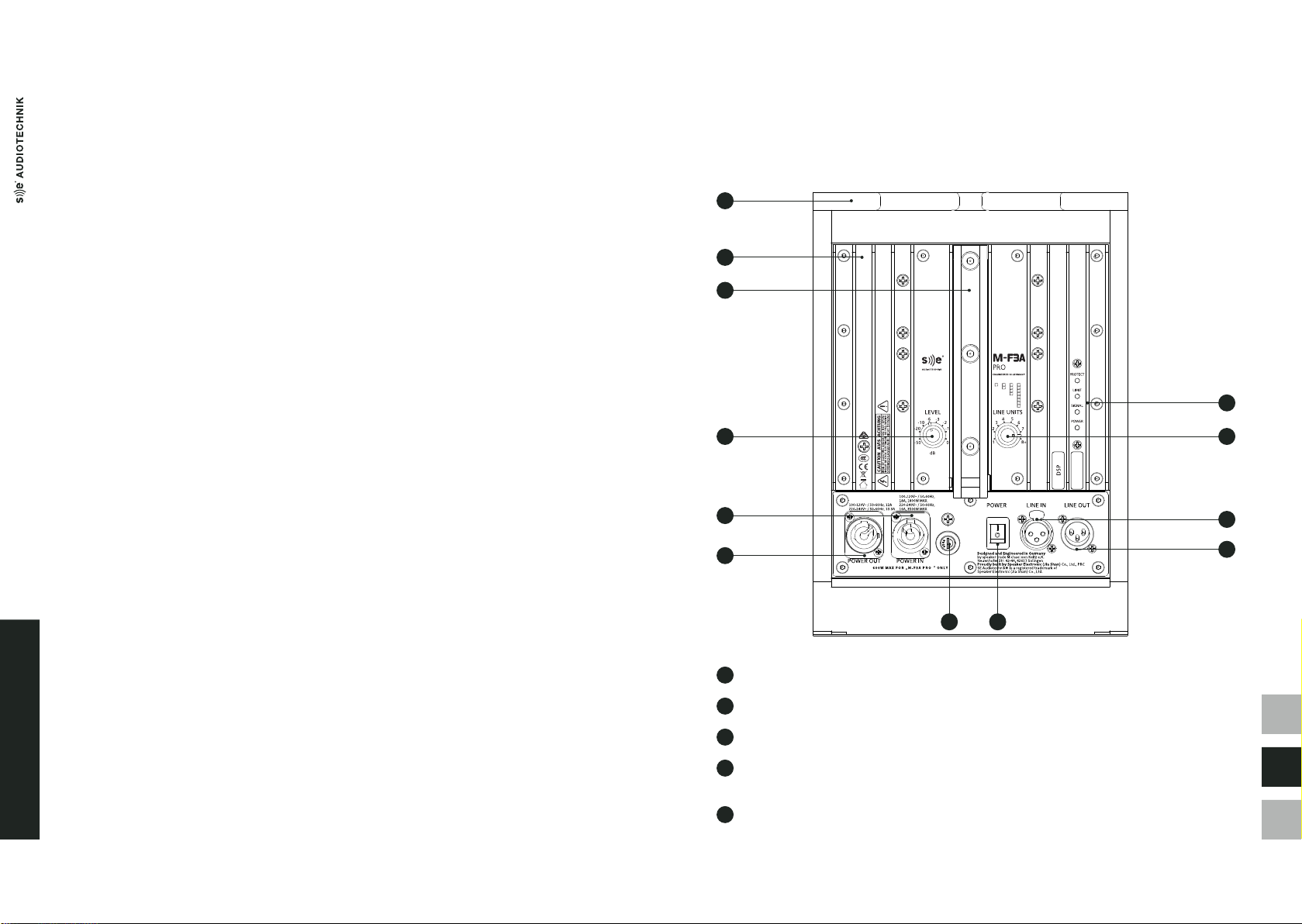
6 Power Out. PowerCON® type-B mains power output to link power between several units in the line.
The recommended maximum quantity of units to be connected in series is 6 units for
200-240 VAC mains, and 3 for 100-120 VAC.
7 Indicator LEDs:
- Protect: Lights red if the amplier has short-circuited or overheated – the device will be muted
automatically. Upon reaching standard conditions, the device reverts to normal operating mode
after a few seconds.
- Limit: Lights orange when the limiter starts working. If the limiter LED lights up permanently or for
longer periods, the gain level should be reduced. Failure to do so may result in a distorted sound.
- Signal: Lights green as soon as an audio signal is present. The input signal monitoring is performed
before the Main Level controller.
- Power: Lights green once the system is properly connected to the mains power and switched on.
8 Line Units. 8-position rotary switch to select the number of M-F3A PRO units in the array. On each
M-F3A PRO, specify the same quantity as units in the line. For example, select "5" on all devices in
an array of 5 units.
Acoustically, the bigger the line array, the greater the interference in the HF and from a lower
frequency. Choosing the right setting helps to improve the HF coupling and provides balanced
sound in all system sizes. Also, in combination with a dedicated multi-band limiter, it helps to
keep the same sound character on all SPL levels.
Since each position sets an equalization designed precisely for that specic line length, this
feature must be used correctly. Setting values dierent than the units in the line, may reduce
the headroom of the system and alter its sound quality.
Finally, when using 8 or more units, specify "8+" on all. For more than 12 units, additional HF
compensation above 2 kHz may be required.
In M-F3A units, this knob is named "High Shelf" and follows the same logic as the "LINE UNITS" in
M-F3A PRO. Thus, it can be used to equalize the array according with the number of units it includes.
9 Line In. Balanced line-level input with female Neutrik® XLR-3 connector to connect input signal. It
allows input levels up to +20 dBu.
For an optimal signal-to-noise ratio, it is recommended to input signals with a level of at least
0 dBu.
10 Line Out. Balanced and buered line-level output with male Neutrik® XLR-3 connector to link other
M-F3A PRO speakers or other components like subwoofers to the system.
11 Fuse.
12 Power. Switch to turn the unit on and o.
To avoid clicks and pops, turn on your PA system last and turn it o rst before other connected
devices. Additionally, after turning the unit o, wait for more than ve seconds before turning it
on again.
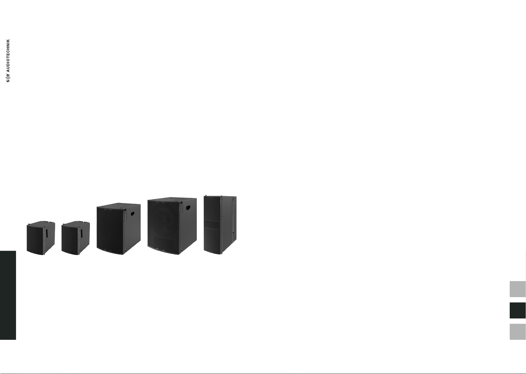
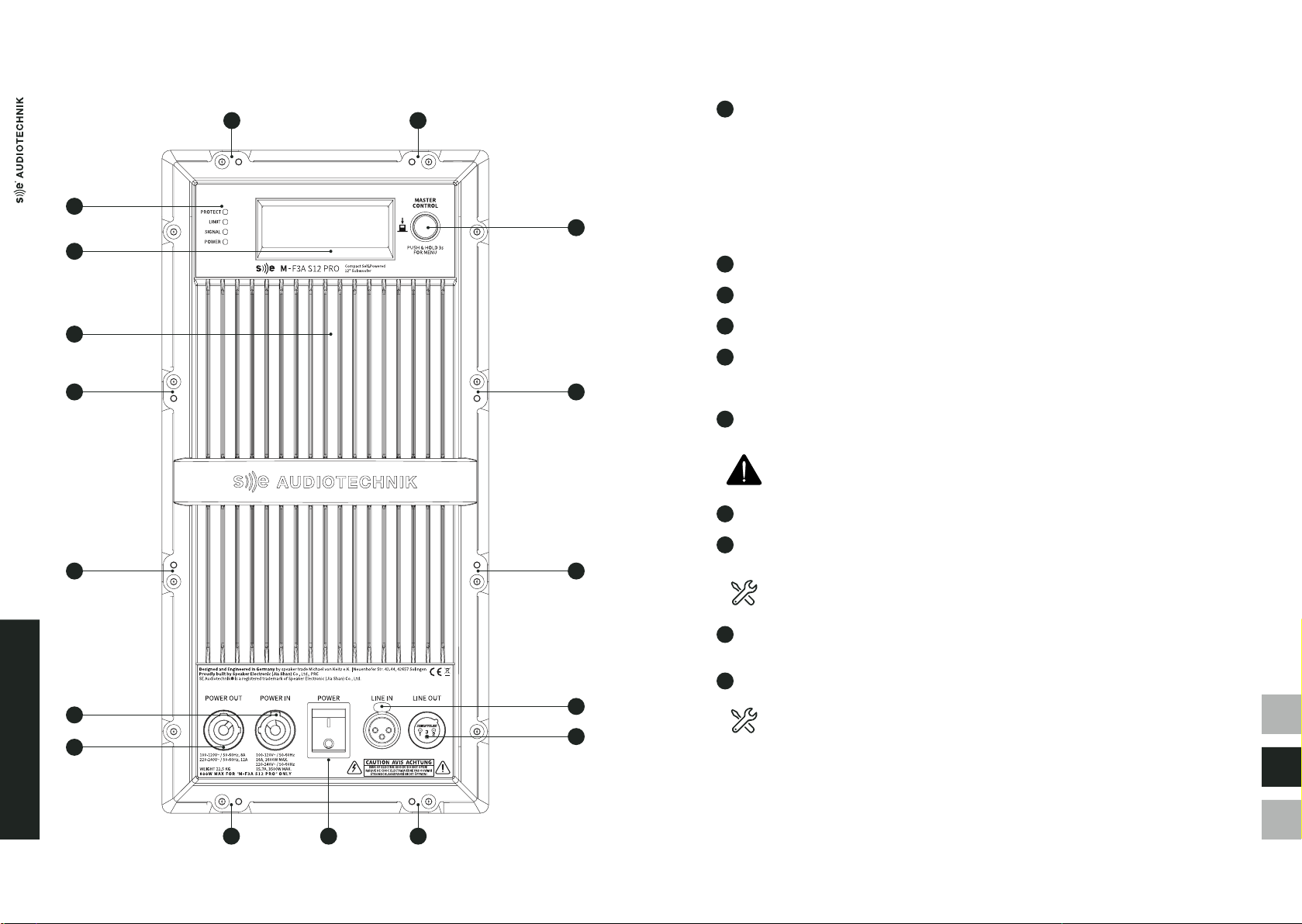
S12 PRO AND S15 PRO SUBWOOFERS
The S12 PRO and S15 PRO are compact active subwoofers designed especially for the M-Line systems.
They are composed respectively by a single 12" and 15" driver in a vented box, powered by an 800 W
Class-D amplier. Its ecient design and compact size guarantees exible placement in all kinds of
environments. In addition, a two-point SE rigging system allows for safe and easy stacking.
These units contain a newly designed 800 W Class-D power amplier and are equipped with 48 kHz/24 bit
DSP. By using the LCD screen and rotary encoder, users can easily control various system parameters such
as delay, EQ, lters and more.
The built-in presets signicantly reduce setup times for M-Line systems in various congurations -
for example, simply select the preset for End-re or Cardioid arrays or a combination with a ysub.
User-dened custom-presets can also be stored.
Features
- Increased SPL with reduced port-noise
- DSP-Presets for quick and easy subwoofer array setups
- Ultra-compact subwoofer, weighing only 23 kg
- Built-in DSP and 800 W of class-D amplication
- Easy to use LCD screen and rotary encoder controller
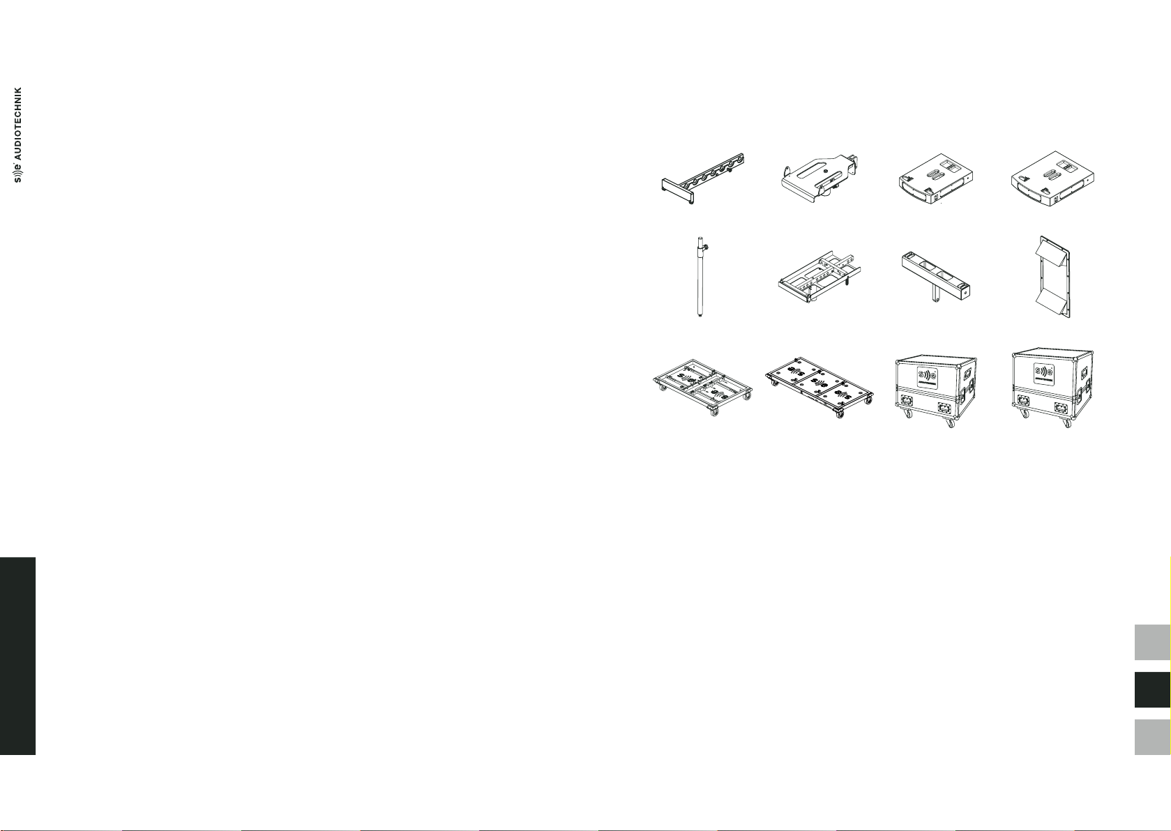
- Two-points rigging system for safe and easy stacking
- Wide range of possible applications
- Available in black and white

中文
EN
D
M-LINE PRODUCTS
1716
REAR PANEL
Figure 3. S12 PRO, S15 PRO and M-F3A FS rear panel.
1 Indicator LEDs:
- Protect: Lights red if the amplier has short-circuited or overheated – the device will mute itself
automatically. Reaching standard conditions again, the device reverts to normal operating mode
after a few seconds.
- Limit: Lights orange when the limiter starts working. If the limiter LED lights up permanently or for
longer periods, the gain level should be reduced. Failure to do so may result in a distorted sound.
- Signal: Lights green as soon as an audio signal is present. The input signal monitoring is performed
before the Main Level controller.
- Power: Lights green once the system is properly connected to the mains power and switched on.
2 Alphanumeric LCD for DSP display.
3 Rear panel heatsink.
4 Mounting points for rain cover accessory.
5 Power In. PowerCON® type-A mains power socket. The plate amplier of the three subwoofers is
intended for two operating voltage ranges: 100-120 and 200-240 VAC. The electrical conversion is
done automatically.
6 Power Out. PowerCON® type-B mains power output to link power between several units in
the system.
The recommended maximum quantity of units to be connected in series is 4 units for 200-240
VAC mains, and 2 for 100-120 VAC.
7 Master control. Rotary encoder with push button for DSP control.
8 Line In. Balanced line-level input with female Neutrik® XLR-3 connector to connect input signal.
Maximum input level is +20 dBu.
For an optimal signal-to-noise ratio, it is recommended to input signals with a level of at
least 0 dBu.
9 Line Out. Balanced and buered line-level output with male Neutrik® XLR-3 connector.
Used to link more M-F3A PRO speakers or other components like subwoofers to the system.
10 Power. Switch to turn the unit on and o.
To avoid clicks and pops, turn on your PA system last and turn it o rst before other connected
devices. Additionally, after turning the unit o, wait for more than ve seconds before turning it
on again.
1
4 4
2
3
4
4 4
4
7
5
6
9
8
4 410

中文
EN
D
M-LINE PRODUCTS
1918
M-F3A FS
The M-F3A FS is the yable bass extension module for the popular M-F3A PRO line array systems. It utilizes
two specially designed 6" x 9" woofers that provide high sound pressure levels whilst presenting a sleek
and discreet design. This unit is twice as high as an M-F3A PRO. Thus, the modules complement each other
perfectly in every way.
The unit contains a newly designed 800 W Class-D power amplier and is equipped with 48 kHz/24 bit DSP.
The LCD display and rotary encoder allow the user to select and control various system parameters such as
delay, EQ, lters and other parameters.
Custom congurations can then be saved as user presets. In addition, the built-in factory presets reduce
setup times for existing M-Line systems in various congurations. In example, when own with M-F3A
PRO, the unit can deliver rich and deep bass to manage applications where no space for ground subs is
available.
Improved rigging capabilities and the newly-designed extended bumper frame gives additional exibility
to integrate this adaptable subwoofer into M-Line systems.
Figure 3 in subsection S12 PRO and S15 PRO Subwoofers depicts its rear panel.
Features
- Lightweight, yable subwoofer, weighing only 23 kg
- DSP-Presets for accurate acoustical coupling with other M-Line products
- Built-in DSP and 800 W of class-D amplication
- LCD screen and rotary encoder for quick and easy DSP control
- Four-points rigging system for safe own setup
- Discreet and aesthetic design for elegant and coherent appearance
- Available in black and white colors
M-LINE ACCESSORIES
The range of applications of the M-Line can be enhanced with the following accessories:
M-F3A BF M-F3A UB M-F3A S12 PRO SFi M-F3A S15 PRO SFi
SPS20 M-F3A FS BF M-F3A FA34 P801DL RC
M-F3A PRO TK44 M-F3A S12 PRO TK32 M-F3A FC M-F3A S12 PRO FC
- M-F3A BF: Bumper frame for ying up to 16 pieces of M-F3A or M-F3A PRO.
- M-F3A UB: U-bracket to install up to two M-F3A or M-F3A PRO units over a pole bar, mounted on any
SE AUDIOTECHNIK® subwoofer with M20 thread.
- M-F3A S12 PRO SFi: Frame for ground stacking M-F3A or M-F3A PRO units on S12 PRO subwoofers.
- M-F3A S15 PRO SFi: Frame for ground stacking M-F3A or M-F3A PRO units on S15 PRO subwoofers.
- SPS20: Pole bar with M20 thread and adjustable height.
- M-F3A FS BF: Bumper frame to y 4-point rigging systems such as M-F3A FS.
- M-F3A FA34: 3-to-4-point rigging adapter for ying M-F3A or M-F3A PRO under M-F3A FS.
- M-F3A CTB: carry-on bag to transport one M-F3A or M-F3A PRO.
- M-F3A PRO TK44: transport kart for up to 16 M-F3A or M-F3A PRO units.
- M-F3A PRO TK32: transport kart for 6 S12 PRO subwoofers.
- M-F3A FC: Flight case for 4 pieces of M-F3A or M-F3A PRO.
- M-F3A S12 PRO FC: Flight case for two pieces of S12 PRO.
- M-F3A S15 PRO FC: Flight case for two pieces of S15 PRO.
- M-F3A PRO FRC 8/12/16: rain cover for own line arrays of 8, 12 or 16 M-F3A PRO.
- P801DL RC: Amplier rain cover to protect the power amplier of the S12 PRO, S15 PRO or M-F3A FS.
- M-F3A PRO FRC 8/12/16: Rain cover for own line arrays of 8, 12 or 16 M-F3A or M-F3A PRO units.
Please, read thoroughly the Application Examples and Rigging and Installation sections for further
information about the setups, deployment and possibilities of the M-Line products.
Figure 4. M-Line accessories.

中文
EN
D
RIGGING AND INSTALLATION
2120
RIGGING AND INSTALLATION
RIGGING COMPONENTS
M-F3A PRO
This product features the following rigging elements:
- Front rigging points: aluminum bars on both sides for frontal xing, including one security pin each.
- Rear rigging piece: steel tracks for splay angle denition with one security pin and an unfolding bar for
rear connection. The available holes allow for dening the tilt of the specic unit in combination with
the previous element.
Since the moving piece of the last unit in an array is not used, it must be locked by inserting
the security pin in the "Stow" position.
- Security pins: 6-mm ball lock pins in stainless steel for safe locking between units.
To lock and unlock them properly:
1. Push and hold the button to release the blocking ball.
2. Insert the pin through the pieces to link.
3. Release the button to close the mechanism. Pull the pin outwards to verify a close and
safe connection.
S12 PRO AND S15 PRO
This product features the following rigging elements:
- Top holes and bottom rubber feet: included to indicate the correct position, assuring a rm grip
when stacking S12 PRO or S15 PRO subwoofers.
- Side locking points: Male lever on the top of the cabinet and the female receptacle on the bottom.
These must be locked when S12 PRO or S15 PRO subwoofers are used in stacked systems as described
below and shown in gure 7:
1. Pull the handle to release the blocking piece.
2. Move the lever upwards to the receptacle of the unit above.
3. Release the handle to close the mechanism. Try to move the lever downwards to verify a close
and safe link.
Figure 5. Front and rear rigging pieces of the M-F3A PRO units.
Figure 7. Linking system for stacks in S12 PRO and S15 PRO subwoofers.
Figure 6. Manipulation of the security pins in the M-Line products.
1 32
Stack
Snap
3
2
1

中文
EN
D
RIGGING AND INSTALLATION
2322
M-F3A FS
This product features the following rigging elements:
- Front rigging points: aluminum bars on both sides for frontal xing, including each one security pin.
- Rear rigging piece: steel tracks on both sides for tilt denition and rear linking with the next unit. In the
upper part, these include a security pin and 9 holes to select the splay angle from 0° to 8°, in 1° steps.
On the bottom, a deployable bar can be placed in three positions depending on the need:
- Lowest hole: to hide completely the moving bar when no other device will be added below the
yable subwoofer, or for its safe storage and transport. See drawing A in gure 8.
- Center hole: to attach an M-F3A FA34 adapter, which allows to add one or more M-F3A or
M-F3A PRO units. See drawing B in 8.
- Upper hole: to link another M-F3A FS below. In this position the bar is completely out and denes
the splay angle of the next subwoofer. See drawing C in gure 8.
- Security pins: 6-mm ball lock pins in stainless steel for safe locking between units, manipulated as
shown before in gure 6.
Figure 8. Rear rigging piece in M-F3A FS subwoofers.
INSTALLATION
For all installations, use SE AUDIOTECHNIK® accessories only. Also, please follow thoroughly
the steps specied for each of these setups, and respect the security directions and warnings
given in the section Important Safety Instructions.
Use SE AUDIOTECHNIK® accessories only for all installations Please, follow thoroughly the steps specied
for each of these setups, and respect the security directions and warnings given in the section Important
Safety Instructions.
When rigging and installing line array systems, please mind the following security advices:
- Adhere to and respect any local regulation regarding manipulation and hoisting of heavy loads.
- Inspect the conditions of all the equipment, accessories and tools to be used. Make sure no one
presents any fault or damage that may endanger or compromise safety.
- Check that the standing surfaces and holding structures are safe, stable, and can hold the weight of
the designed array.
- Arrange an appropriate working environment, clear and free from unnecessary or dangerous objects.
- When installing products above head height, always use a proper ladder or industrial lift.
- Use appropriate protective elements, as good and stable shoes and clothes.
- When deploying own arrays, always add just one piece at a time.
- Remain attentive to any risk of crushing.
- Do not stand below hanging loads.
A B C

中文
EN
D
RIGGING AND INSTALLATION
2524
M-F3A UB
The M-F3A UB U-bracket allows to install one or two M-F3A or M-F3A PRO pieces on any
SE AUDIOTECHNIK® subwoofer with M20 thread, using the SPS20 pole mount.
Under no circumstances should you use the M-F3A U-bracket to hang line array systems!
In addition, no more than two M-F3A or M-F3A PRO units should be stacked on top of it.
To prepare the units and accessories before install the setup:
1. Prepare the power and audio cables required for the installation.
2. Adjust the same "LEVEL" and "LINE UNITS" on each of the M-F3A or M-F3A PRO units.
3. Using the screws of the SPS20 pole mount, set its length to the minimum. Seal them again
before proceeding.
To install the system:
1. Locate the subwoofer in the desired place. Ensure that the four bottom feet touch the ground and its
position is stable.
2. Screw the SPS20 pole mount in the M20 thread of the subwoofer.
3. Place the receptacle of the M-F3A UB bracket in the SPS20 pole mount. Fasten it tight with the screw.
4. Position the rst M-F3A or M-F3A PRO unit over the U-bracket. Lock the two lower front rigging points
of the box with the security pins of the U-bracket.
5. Unfold the moving part in the back of the box and set the aiming angle with the holes in the U-bracket.
Use the security pin of the u-bracket to lock it.
6. Repeat steps 4 and 5 to install a second M-F3A or M-F3A PRO unit on top of the rst one if desired.
7. Lock the security pins in the front of the last unit added to the stack.
8. Loosen the screws in the SPS20 pole mount and lift the top units until the desired height. Seal again
the screws in the pole to lock the position.
9. Connect properly the power and audio cables and turn the units ON.
To unmount the system, follow the previous steps in reverse order respecting all the safety instructions
mentioned before.
Figure 9. Installation of small arrays with the SPS20 pole mount and the M-F3A UB U-bracket.
M-F3A S12 PRO SFI AND M-F3A S15 PRO SFI
With these dedicated frames, it is possible to stack up to 4 M-F3A or M-F3A PRO units over a S12 PRO or
S15 PRO subwoofer, or on the ground.
M-F3A S12 PRO SFi or M-F3A S15 PRO SFi stacking frames are not designed for hanging loads.
Under no circumstances should you use them to hang line array systems! In addition, no more
than four M-F3A or M-F3A PRO units should be stacked on top of it.
Before installing the system:
1. Prepare the power and audio cables required for the installation.
2. Depending on the number of boxes in the array, set the same "LINE UNITS" on each of the M-F3A
or M-F3A PRO units to use.
3. Set the "LEVEL" control to the same position on all the boxes, and turn their power switch to the
ON position.
To set an array over one S12 PRO or S15 PRO subwoofer:
1. Locate the subwoofer in the desired place. Ensure that the four bottom feet touch the ground and
its position is stable.
2. Fix the M-F3A S12 PRO SFi or M-F3A S15 PRO SFi stacking frame to the subwoofer using the
locking points located at both sides, as shown in gures 7 and 10.
3. Follow the steps described below for a ground-stacked array.
Figure 10. Subwoofer ground stack with M-F3A S12 PRO SFi and M-F3A S15 PRO SFi frames.
M-F3A PRO
M-F3A UB
SPS 20
S12 PRO 1
2
3
4
4 5
5
Snap
1
2
3
4

中文
EN
D
RIGGING AND INSTALLATION
2726
When this kind of setup is done with the M-F3A S12 PRO SFi or M-F3A S15 PRO SFi on the ground:
1. Release the three security pins of the stacking frame.
2. Place the rst M-F3A or M-F3A PRO unit over the stacking frame. Fasten the two lower front rigging
points of the box with the security pins of the frame. See gure 12.
3. Unfold the moving part in the rear of the box and lock it with the rear security pin of the stacking
frame. As shown in gure 11, set the desired aiming angle with the three positions available:
0°, -2.5° and -5°.
4. Place the next M-F3A or M-F3A PRO unit over the previous one. Fasten the two lower front rigging
points of the second box with the security pins of the rst one.
5. In the rear part, set the desired splay angle for the new unit linking its moving piece with the rear
track of the previous one.
6. Connect properly the power and audio cables for the last unit added.
7. Repeat the three previous steps to install more M-F3A or M-F3A PRO units on top of the rst ones,
as shown in gure 12. No more than 4 boxes should be stacked with this frame.
8. Finally, lock the security pins in the front of the last unit added to the stack.
To unmount the system, follow the previous steps in reverse order respecting all the safety instructions
mentioned before.
Notice that the previous setup can also be done on top of stack of S12 PRO or S15 PRO
subwoofers, deployed as indicated in the gures 7 in subsection Rigging Components.
In those cases, maximum 3 S12 PRO and 2 S15 PRO subwoofers should be stacked.
Figure 12. Installation of stacked arrays with the M-F3A S12 PRO SFi and M-F3A S15 PRO SFi frame.
Figure 13. Suspension of the M-F3A BF bumper frame using one or two points.
M-F3A BF
The M-F3A BF bumper frame allows to deploy safely line array systems of even 16 M-F3A or M-F3A PRO
units. As shown in gure 13, one or two points can be used to hang the bumper frame. Keep in mind that
the tilting of the whole array depends on several factors as the amount of units, the splay angle between
them, other added weight like cables, and the pick-up point chosen in the bumper frame.
The maximum supported weight for the M-F3A FS BF and M-F3A 34 accessories are 2,700 kg and
1,000 kg respectively. Care must be taken to not exceed these limits.
The suspension of this frame must be done over a structure using hoisting chains that can resist
loads greater than the weight of the array.
Figure 11. M-F3A S12 PRO SFi and M-F3A S15 PRO SFi rear holes for angle denition.
-5° -5°0° 0°
-2.5° -2.5°
1
2
3
5
5
5
4
4
4

中文
EN
D
RIGGING AND INSTALLATION
2928
To prepare the system before the installation:
1. Prepare the power and audio cables required for the installation.
2. Depending on the number of boxes in the array, set the same "LINE UNITS" on each of the M-F3A
or M-F3A PRO units to use.
3. Set the "LEVEL" control to the same position on all the boxes, and turn their power switch to the
ON position.
To deploy the system:
1. Connect the M-F3A BF bumper frame to the hoist chain/s using appropriate shackle/s in the
hole/s selected for the desired tilting.
2. Lift the bumper frame to a comfortable height and attach the rst M-F3A or M-F3A PRO unit.
With the security pins, link the two front points of the rst unit, to the front points of the frame.
3. Release the moving piece on the rear side of the rst unit. Link the xed rigging piece to the rear
hanging bar of the bumper frame, using the hole for a 0° angle.
4. If needed, lift the array to a comfortable height.
5. Add the second unit below the rst one, linking its top rigging points with the bottom points of
the rst one.
6. Unfold the moving part in the rear of the second box.
7. Connect the rear rigging piece of the second box with the deployable bar of the rst one. Lock
the security pin of the new box in the correct hole, setting the desired aiming angle with the nine
positions available, as shown in gure 14.
Figure 14. Front and rear linking in M-F3A PRO line arrays.
0° 8°
8. Connect properly the power and audio cables for the units added.
9. Repeat steps 4 to 8 until the whole system is suspended and connected.
10. Before hoisting the line array to the nal position, inspect thoroughly:
a. Bumper frame: Check the connection of the hoist chain and the rst unit.
b. Rigging points and security pins: Be sure they all are correctly locked in place.
c. Splay angles: Verify the values established are correct.
d. Connections: Review the proper power and audio signal ow between boxes.
e. Units conguration: Double-check that all the units are turned ON and have the same
"LEVEL" and "LINE UNITS" values.
To unmount the system, follow the previous steps in reverse order respecting all the safety instructions
mentioned before.
M-F3A FS BF
The M-F3A FS BF is a dedicated bumper frame for M-F3A FS subwoofer line arrays. Same as the M-F3A BF,
this bumper frame can be suspended from one or two points, as shown in gure 15. In addition, the
M-F3A 34 adapter can be used to add below arrays composed by M-F3A or M-F3A PRO units.
The maximum supported weight for the M-F3A FS BF and M-F3A 34 accessories are 2,700 kg and
1,000 kg respectively. Care must be taken to not exceed these limits.
The installation of this frame obeys the same warnings and indications given previously for the
M-F3A BF.
The moving piece in the M-F3A 34 adapter allows to dene only 0°, 1° and 2° splay angles for the
unit connected to it.
Figure 15. Suspension of the M-F3A FS BF bumper frame using one or two points.

中文
EN
D
RIGGING AND INSTALLATION
3130
To prepare the system before the installation:
1. Prepare the power and audio cables required for the installation.
2. Set the appropriate preset and DSP functions for the M-F3A FS subwoofer/s to deploy.
3. If applicable and depending on the number of boxes in the array, set the same "LINE UNITS" on
each of the M-F3A or M-F3A PRO units to use. Also, set the "LEVEL" control to the same position
on all the boxes.
4. For all the products and units to use, turn the power switch to the ON position.
To deploy a line array composed by subwoofers:
5. Connect the M-F3A FS BF bumper frame to the hoist chain/s using appropriate shackle/s in the
hole/s selected for the desired tilting. See gure 16.
6. Lift the bumper frame to a comfortable height and attach the rst M-F3A FS subwoofer.
With the security pins, link the two front points of the rst unit, to the front points of the frame.
7. Lock the upper rear part of the subwoofer by fastening the top security pins with the rear
releasable bars of the M-3A FS BF bumper frame. See gure 16.
8. Lift the bumper frame to a comfortable height and release the rear deployable bars of the rst
subwoofer. Fix them in the upper hole, leaving most of their length outside.
9. Attach the second subwoofer below the rst one. With the security pins, link the two front points
of the new unit, to the front points of the rst one.
10. Lock the rear part of the new subwoofer by fastening the top security pins with the rear releasable
bars of the rst one. Pick the right holes to set the desired splay angle.
11. Connect properly the power and audio cables for the units added.
12. Repeat steps 7 to 10 until all the subwoofers are suspended.
To add a line array of M-F3A or M-F3A PRO units under a own M-F3A FS subwoofer:
4. Lift the bumper frame to a comfortable height and release the bars in the rear of the subwoofer.
Fix them in the middle hole, where half of their length is exposed.
5. Attach the M-F3A 34 adapter by inserting the deployable bars of the subwoofer, in the outermost
slots of the adapter. Fasten it locking its two security pins through the bars.
6. Add the rst M-F3A or M-F3A PRO unit by attaching the two upper front points, to the lower front
points of the subwoofer.
7. Release the rear deployable bar of the new unit. Secure the box in the back by linking its rear
rigging piece with the moving bar in the M-F3A 34 adapter. Lock the security pin of the box in the
hole for the 0° angle.
8. Connect properly the power and audio cables for the rst unit.
9. Add the second M-F3A or M-F3A PRO unit below the rst one. Link its top rigging points with the
bottom points of the rst one.
10. Unfold the moving part in the rear of the second box.
11. Connect the rear rigging piece of the second box with the deployable bar of the rst one. Lock the
security pin of the new box in the correct hole to set the desired splay angle.
12. Connect properly the power and audio cables for the unit added.
13. Repeat steps 9 to 12 until the whole system is suspended and connected.
14. Before hoisting the line array to the nal position, inspect thoroughly:
a. Bumper frame: Check the connection of the hoist chain and the rst unit.
b. M-F3A 34 adapter: Check the connection of the last M-F3A subwoofer and the rst M-F3A or
M-F3A PRO unit.
c. Rigging points and security pins: Be sure they all are correctly locked in place.
d. Splay angles: Verify the values established are correct.
e. Connections: Review the proper power and audio signal ow between boxes.
f. Units conguration: Double-check that all the units are turned ON, the preset selected for the
subwoofers, and that the M-F3A or M-F3A PRO units have all the same "LEVEL" and "LINE
UNITS" values.
To unmount the system, repeat the previous steps in inverse order respecting all the safety instructions
mentioned before.
Figure 16. Attaching the M-F3A FS subwoofer to the M-F3A FS BF frame.
5
6
6
7
7

中文
EN
D
LCD PLATE AMPLIFIER
XLR-3 IN
Click Click 2 21 1
3 3
XLR-3 OUT
Connection
XLR-3 Female
Shield
Cold
Hot
XLR-3 Male
Wiring Scheme
3332
WIRING
M-Line products use PowerCON® connectors for the mains power input and link. Figure 17 shows how to
plug-in and connect these wires.
It is recommended to use cables with at least 18 AWG conductor size. For long cable lengths, the maximum
conductor size is 14 AWG. Those wires must be assembled by a qualied technician.
Conversely, M-Line products use XLR-3 connectors to input and loop audio signals. They follow the next
plug-in and conguration scheme:
Figure 17. PowerCON® plug-in and link cable connection.
powerCON IN powerCON 1
L
L
N
N
powerCON OUT powerCON 1
Connection Wiring Scheme
L
N
2
1
Figure 18. XLR-3 plug-in and cable connection.
LCD PLATE AMPLIFIER
The S12 PRO, S15 PRO and M-F3A FS subwoofers are equipped with a built-in 48 kHz/24 bit DSP
processor,that provides controlled signal processing and limiting. This DSP core is fed by dual-range
inputs to improve the SNR, and is easy to manipulate thanks to the rotary control encoder with push
button, and the 4x20 symbol alpha-numeric LCD screen.
This section details the features of the DSP rmware, whose adjustable parameters and features include
5 EQ bands, delay, polarity and selection of low-pass lters. Also, S12 PRO has an additional high-pass
lter, and S15 PRO the new directivity control function. In addition, a variety of factory presets is available
in both subwoofers, to easily setup dierent systems.
Some key cursors, symbols and considerations used throughout the menu structure are:
- The rst line of each screen is the specic name or title of the given screen.
- The cursor ">" marks the current point of action.
- When editing preset names, the cursor "←" indicates deleting function.
- The symbol "*" highlights the selection of a given preset or setting. It indicates also that the edition
of a given parameter is enabled.
- The symbol "L" indicates the lock state of the amplier and thus, that the editing of any parameter is
not allowed. This symbol appears only when this is activated, and only in the Overview screen.
Figure 19 shows the dierent menus and functions of the DSP rmware, structured in the following
subsections. Conversely, gures 24 and 38 show respectively the functions included in the
DSP Settings and System Settings.
OVERVIEW
MENU
DSP SETTINGS SYSTEM SETTINGS
Push Push 3sTurn & Push
Mute/Unmute Current PresentOutput Level
Turn
Figure 19. DSP rmware functions and menus.

中文
EN
D
LCD PLATE AMPLIFIER
3534
OVERVIEW SCREEN
The Overview screen is the one shown by default on the amplier LCD, during normal operation
(Figure 20). It details the next information:
- The rst row shows the title of the screen and if applicable, the "L" letter in the top right-corner,
informing the lock state of the amplier.
- The second row reads "IN:", followed by a numerical input level meter. The meter shows the current
input level value in dB FS, with minimum "-90" for low or no signal. The ">>>" symbols show the
signal strength relative to the clipping point at 0 dB FS. The readout is replaced with text "INPUT
CLIPPING!" if the signal reaches or exceeds 0 dB FS. In such case, the screen backlight is ashing to
call the attention of the user.
- The third row reads "OUT:" followed by the output level meter. This meter shows current output
level relative to the maximum amplier output. If the channel is muted, the level display meters are
replaced with the text "MUTED".
- The fourth row shows the gain reduction in dB "GR:" applied to the signal when the limiter threshold
is reached. When the value increases, new levels appear from right to left, according with the amount
of reduction applied.
From the Overview screen, the following options can be executed with the Master Control rotary encoder:
1. Turn left or right to adjust the output level (Figure 21). The output gain and the relative change in dB
are shown. The output level is always recalled and is not aected by any reset function. A value of
0.0 dB refers to the nominal output gain of the subwoofer.
2. Turn just one step and push to quickly mute or unmute the amplier output.
3. Push (without turning) to open the Active Preset Info screen and see both the active preset and the
delay currently dened (Figure 22). Clicking "Back" will return to the Overview screen.
Letters "CA" after the name of the preset indicate that the cardioid directivity function is enabled.
End-re function is denoted as "EF" and normal radiation shows no additional letters.
OVERVIEW
IN:
OUT:
GR:
-10
-02
12
>>>>>>>>
>>>>>>>>>>>
654321dB
Figure 20. Overview screen.
Figure 22. Active Presets View.
Figure 23. Main Menu.
Figure 21. Turning the encoder in Overview screen allows to change output gain.
Out Gain: -6.0 dB
Change: -3.0 dB
OUT:-08 >>>>>>>>>>>
GR: 6 5 4 3 2 1dB
4. Press and hold 3 seconds to enter the MENU.
MENU
To enter the MENU of the amplier, press and hold the Master Control rotary knob for 3 seconds.
A menu as shown in Figure 5 will appear on the screen.
Two submenus can be accessed from this point:
- DSP Settings: signal processing settings such as presets, lters, EQ, delay are congured here.
- System Settings: power amplier operation settings are congured here.
Clicking "Exit" will return to the Overview screen
ACTIVE PRESET INFO
MF3AP : Default CA
USER DELAY:
0.64 ms > BACK
MENU
> DSP Settings
System Settings
Exit

中文
EN
D
LCD PLATE AMPLIFIER
3736
DSP SETTINGS
DSP Settings menus for S12 PRO, S15 PRO and M-F3A FS are shown below in gures 24a, 24b and 24c
respectively.
DSP SETTINGS > PRESET LIBRARY
Preset Library menu allows to load and save DSP processing presets. These are divided in two basic
types:
- Factory presets: these are the default conguration for each SE AUDIOTECHNIK®'s speaker intended
to be used with your subwoofer and contain the information about factory pre-dened lter and
limiter settings.
They are marked with "F" at the right side of the preset name and more details can be found in the
Factory Presets subsection.
- User presets: 8 possible custom congurations to dene freely, taking the factory presets as starting
point and saving additional adjustments, as:
- User High-pass lter settings
- User Low-pass lter settings
- User EQ settings
- User Delay settings
- User Phase Inversion (Polarity) settings
They are marked with "U" at the right side of the preset name.
As mentioned, the active preset is marked with the "*" symbol.
DSP Settings
> Back
Preset Libary
Highpass Filter
Lowpass Filter
Directivity
Phase Inversion
EQ 1
EQ 2
EQ 3
EQ 4
EQ 5
Bypass User EQ
Delay
Reset User Params
Exit
DSP Settings
> Back
Preset Libary
Lowpass Filter
Directivity
Phase Inversion
EQ 1
EQ 2
EQ 3
EQ 4
EQ 5
Bypass User EQ
Delay
Reset User Params
Exit
DSP Settings
> Back
Preset Libary
Highpass Filter
Lowpass Filter
Phase Inversion
EQ 1
EQ 2
EQ 3
EQ 4
EQ 5
Bypass User EQ
Delay
Reset User Params
Exit
Figure 24a. DSP Settings menu for S12 PRO. Figure 24b. DSP Settings menu for S15 PRO. Figure 24c. DSP Settings menu for M-F3A FS.
PRESET LIBARY
Back
> MF3A
MF3A-P
GENERAL
EMPTY: USER 1
EMPTY: USER 2
FO
F
F
U
U
Figure 25. Preset Library menu.
Figure 26. Loading factory preset.
Figure 27. Saving user preset.
The names of the presets always starts with a reference to the loudspeaker model which the preset has
been made from. This way the user knows what factory preset was the origin of the custom user preset.
DSP SETTINGS > PRESET LIBRARY > PRESET LOADING
To load a preset, scroll to the desired one and click the rotary controller. A dialogue is displayed on the
screen to either load preset, save preset or go back. By pressing "Load Preset", the preset is loaded in the
DSP and the message "Load Done" is displayed shortly on the screen.
To return to the Preset Library, choose "Back" and click the rotary controller.
DSP SETTINGS > PRESET LIBRARY > PRESET SAVING
To save a preset, choose one of the existing or empty user preset locations and click the rotary encoder.
A dialogue similar to factory preset loading is displayed on the screen but in this case, an additional
option is available to save the preset. Saving is only available in the user presets.
FACTORY PRESET
MF3A : Default
Back
> Load Preset
EMPTY: USER 1
Back
Load Preset
Save Preset>
USER PRESET

中文
EN
D
LCD PLATE AMPLIFIER
3938
Clicking on "Save Preset", starts a dialogue to dene the preset name. By default, the rst characters of
the name are the same as the currently loaded preset and these can not be changed. Thus, before setting
and saving any user preset, a factory preset needs to be active.
To customize the name of the new preset, edit the last characters after ":". To do this:
1. Set the cursor ">" on the name and click the encoder. The "*" symbol appears to indicate, that the
name is editable now.
2. Turn the controller to choose the character and set it by pressing the button. To delete a character,
choose "←" symbol and click.
3. Complete the editing by choosing the space symbol "_" and click twice.
To conrm the preset saving, choose "Save" and click the rotary controller. The message "Save Done"
is shortly displayed on the screen. To return to the Preset Library, choose "Back" in the succeeding two
screens.
DSP SETTINGS > PRESET LIBRARY > PRESET INFORMATION
Press and hold the rotary knob for 3 seconds on the selected preset to open the Preset Information dialog.
In the latest rmware version, the Name, Date, Version and Author are displayed and shall be used to
ensure that the speaker presets are up to date.
DSP SETTINGS > HIGHPASS FILTER (S12 PRO AND M-F3A FS ONLY)
The Highpass Filter section allows to change the cut-o frequency of the high-pass protection lter.
The lowest possible setting is an electrical 4th order, tuned for S12 PRO at 36 Hz, and for M-F3A FS at 55 Hz.
These lters are always enabled.
All frequency steps above the lowest option correspond to an acoustical 6th order Butterworth lter.
These additional values are:
- S12 PRO: 48, 50, 53, 56, 60, 63, 67, 71, 75, 80, 85, 90, 95 and 100 Hz.
- M-F3A FS: 55, 65, 67, 70, 73, 76, 80, 85, 90, 95 and 100 Hz.
Changing this cut-o frequency can be useful mainly when the S12 PRO or M-F3A FS are used with other
subwoofers that cover the lower frequency bands. To do this:
1. Set the cursor ">" on the option "Freq" and click the encoder. The "*" symbol indicates editability of
the setting.
2. Turn the controller to choose the desired value and set it by pressing the button.
3. Choose "Back" and click the rotary controller to return to the DSP Settings submenu.
DSP SETTINGS > LOWPASS FILTER
The DSP of the subwoofer also includes an adjustable Lowpass Filter . This submenu allows to change its
type, slope and cut-o frequency, and to bypass it.
> MF3A : _Club__
Back
Save
SAVE USER PRESET
_
Figure 28. Saving user preset.
Figure 29. Preset information dialog.
> Back
MF3A : DLY Line U
Date: 20170629
Based-On: 0.6
Orig-Author: 02
PRESET INFORMATION
HIGHPASS FILTER
> Back
Freq. : 36 Hz
Figure 30. High-pass Filter adjustment.
Figure 31. Low-pass Filter adjustment.
LOWPASS FILTER
> Back
Bypass: OFF
Freq: 120 Hz
Type: LR 24dB/Oct
This manual suits for next models
5
Table of contents
Other SE Audiotechnik Speakers System manuals