Sea-Bird Scientific SBE 19plus V2 SeaCAT Quick manual

19plus V2 BUM
SBE 19plus V2 SeaCAT
09/2022, Edition A
Basic user manual
Basic user manual
Basic user manual

Table of Contents
English..............................................................................................................................3
Deutsch.......................................................................................................................... 15
Español.......................................................................................................................... 28
2

Table of Contents
1 SBE 19plus V2 quick start guide on page 3
2 Specifications on page 4
3 Replace alkaline batteries on page 7
4 Charge NiMH batteries on page 8
5 Antifouling devices on page 10
6 General information on page 12
Section 1 SBE 19plus V2 quick start guide
This quick start guide and user manual applies to the SBE 19plus V2 SeaCAT. The full user manual,
with details about setup, operation, and maintenance can be found on the manufacturer's website.
Refer to the full user manual for details about topics shown in italics.
What's in the box:
• CD or USB drive with software, calibration files, documentation
• Dummy plugs and lock collars for each bulkhead connector
• Data I/O cable to connect the sensor to a PC
• Non-ionic surfactant to clean sensor flow path
• Conductivity cell tubing and storage kit
• Spare hardware and O-ring kit.
1. Install the manufacturer-supplied software on a PC. Refer to Install software for details.
2. Connect the data I/O cable to the sensor and the PC and double-click on SeaTermV2.exe to start
the software.
3. If necessary, install new batteries. Refer to Replace alkaline batteries or Recharge NiMH
batteries for details.
4. Make sure that all data stored in the sensor is transmitted to a PC.
5. Set the date and time and configure the data collection settings.
6. Install dummy plugs and lock collars on bulkhead connectors that are not used.
7. If necessary, remove the end-to-end loop of Tygon® tubing from around the conductivity cell. It is
used when the SeaCAT is in storage.
8. Connect the tubing from the pump to the conductivity cell.
9. Send the DS and DCal commands to verify status and calibration coefficients.
10. Moored Mode (MM): use StartNow to start data collection every SampleInterval= x seconds.
11. Moored Mode (MM): use StartDateTime= and StartLater to start data collection at a specified
date and time, every SampleInterval=seconds.
12. Profile Mode (MP), as necessary:
• Put the magnetic switch in the On position, or
• If IgnoreSwitch=Y, send commands to start data collection now, with StartNow, or in the future,
with StartDateTime= and StartLater to start data collection at a specified date and time, or
• If AutoRun=Y, apply external power.
13. Deploy the sensor. For most applications, make sure the connector is at the bottom (lowest
point).
14. Immediately after the sensor is recovered from a deployment:
a. Transmit data from the sensor to a PC. Refer to Transmit data for details.
b. Turn off the sensor.
c. Flush the sensor with fresh water.
d. Keep the SeaCAT out of direct sunlight between deployments.
15. Refer to Prepare sensor for storage for details to prepare the sensor for short- or long-term
storage.
English 3
Section 2 Specifications
2.1 Mechanical
Weight, 600 m, plastic, no pump, in air, water 7.3, 2.3 kg
Weight, 10500 m, titanium, no pump, in air, water 13.7, 8.6 kg
Weight, 5M, plastic 0.3, 0.1 kg
Weight, 5M, titanium 0.3, 0.4 kg
Weight, 5T, P, plastic 0.5, 0.1 kg
Weight, 5T, P, titanium 0.7, 0.3 kg
Depth rating, acetal plastic 600 m
Depth rating, 3AL–2.5V titanium 7000 m
Depth rating, 6AL–4V titanium 10500 m
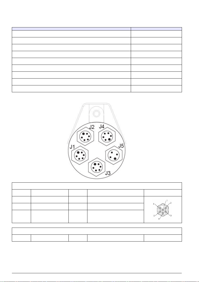
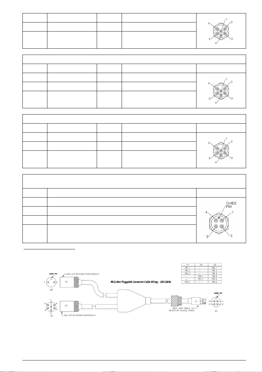
2.1.1 Connectors and cables
J1 auxiliary differential input 0,1
Contact Function Contact Function MCBH6MP
1 Common 4 Voltage 1 signal
2 Voltage 0 signal 5 Voltage 1 common
3 Voltage 0 common 6 Auxiliary power out
J2 auxiliary differential input 2, 3
Contact Function Contact Function MCBH6MP
4 English

1 Common 4 Voltage 3 signal
2 Voltage 2 signal 5 Voltage 3 common
3 Voltage 2 common 6 Auxiliary power out
J3 data I/O, pump, external power
Contact Function Contact Function MCBH6MP
1 Common 4 Pump power common
2 RS232 data RX 5 Pump power
3 RS232 data TX 6 Auxiliary power in, 9–28 VDC
J4 auxiliary differential input 4, 5
Contact Function Contact Function MCBH6MP
1 Common 4 Voltage 5 signal
2 Voltage 4 signal 5 Voltage 5 common
3 Voltage 4 common 6 Auxiliary power out
J5 auxiliary serial input
sensor and 19plus must be set to the same baud rate
Contact Function MCBH4MP
1 Common
2 RS232 data transmit to RS232 sensor
3 RS232 data receive from RS232 sensor
4 Power to RS232 sensor
Figure 1 Y cable
English 5

Figure 2 Data I/O cable
Figure 3 SBE 5 to CTD cable
2.1.2 Dimensions
2.2 Electrical and communications
Input from external power supply 9–28 VDC
Current draw from external power supply, 5M 3 A at 9V, 0.5 A at 12V and 19V
Current draw from external power supply, 5T, 5P 3 A at 12V, 1.5 A at 19V
Current draw, data collection 70 mA
Current draw, 5M pump 100 mA
Current draw, 5T, 5P 150 mA
Current draw, communications 65 mA
Current draw, low power (powered by internal batteries) 20 µA
Internal battery capacity, 9 alkaline D-cells 14 Ah
Internal battery capacity, NiMH pack 8 Ah
Auxiliary power out at 10.5–11 VDC to 500 mA
Voltage A/D resolution 14 bits
Voltage sensor input range 0–5 VDC
Memory 64 MB Flash
6 English

Communication interface RS232
Data collection rate 4 Hz
2.3 Analytical
Parameter Range Accuracy Stability Resolution
Conductivity 0–9 ±±0.005 V 0.0003 S/m per month 0.00007 S/m
Temperature -5–35 °C ±0.005 V 0.0002 °C/mo 0.0001 °C
Pressure,
strain gauge
various to 10,500 m ±0.1% full scale
range
±0.1% full scale range 0.002% full scale
range
Pressure,
quartz
various to 10,500 m ± 0.02% ± 0.02% 0.0025% of full scale
range
Section 3 Replace alkaline batteries
WARNING
If the user thinks that a sensor has water in the pressure housing: Disconnect the sensor from any
power supply. Put on safety glasses and make sure that the sensor is pointed away from the body
and other people. In a well ventilated area, use the purge port (if the sensor is so equipped), or very
SLOWLY loosen the bulkhead connector to let the pressure release.
WARNING
If the user thinks that the alkaline batteries have leaks, pressure may have built up inside of the
pressure housing. Follow ESD protocols to release internal pressure. Put on safety glasses and
protective gloves and make sure that the sensor is pointed away from the body and other people. In
a well ventilated very SLOWLY loosen the bulkhead connector to release the pressure. Keep away
from heat, sparks, flame, and other sources of ignition. Do not smoke.
CAUTION
The pressure housing contains Electrostatic Discharge (ESD) sensitive parts and assemblies that
are susceptible to damage from ESD. Follow ESD protocols:
• Put on protective eye wear before you open the pressure housing.
• Any electrostatic charge on the body of the human operator must be released before the
pressure housing is opened: put a hand on a grounded surface, or better, wear a grounded
antistatic wrist strap.
• At a minimum, wear short-sleeved antistatic clothing, such as cotton, or better, wear an antistatic
smock for this service activity. Do not wear a sweater, fleece or polyester-based clothing.
• At a minimum, use a workstation with a wood or metal tabletop, or better, a tabletop that
dissipates static. Do not use a workstation with a synthetic or polymeric-based tabletop.
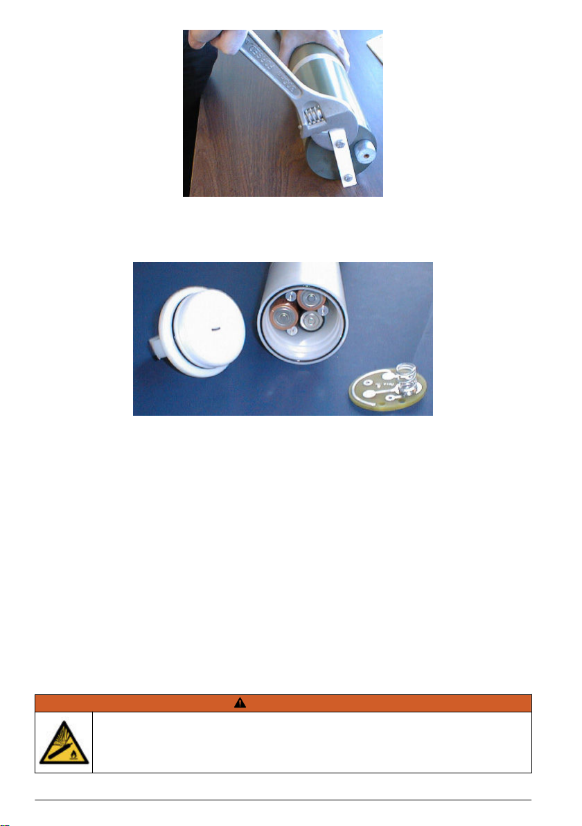
1. Use a clean cloth to dry the outside of the battery end flange. Make sure to remove any water at
the interface between the pressure housing and the end flange.
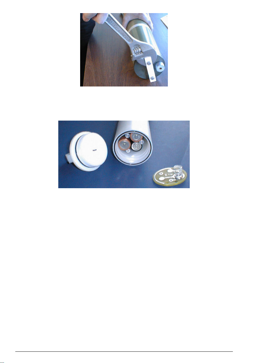
2. Use a wrench on the white plastic bar to turn the end flange counterclockwise to loosen.
English 7
3. Remove any water on all of the O-ring surfaces with a lint-free cloth or tissue.
4. Keep the end flange and make sure to protect the O-ring from contamination or other damage.
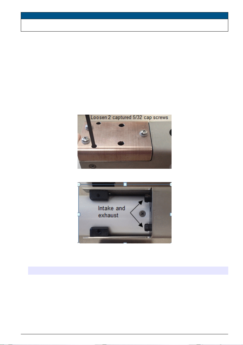
5. Remove the three Phillips-head screws and washers from the battery cover plate.
The battery cover plate will pop out.
6. Remove the batteries.
7. Install new batteries. Make sure the + terminal is on the flat battery contacts and the - terminal is
on the spring contacts.
8. Align the battery cover with the housing. The posts inside the housing are asymmetrical, to the
cover fits into the housing only one way.
One screw hole is closer to the edge than the others and aligns with the post that is closest to the
housing.
9. Install the three Phillips-head screws and washers again: push firmly on the cover to make sure
that the spring is fully in contact with the batteries.
Make sure the screws are fully tightened or battery power will be intermittent.
10. Verify that the battery voltage at BAT + and BAT - on the battery cover is approximately 18 V.
11. Make sure all O-ring surfaces are clean and dry. Replace O-rings as necessary.
12. Apply a light coat of silicone-based Parker Super O Lube to the O-ring mating surfaces.
13. Carefully put the end flange onto the housing and screw the end flange into place. Use a wrench
to make sure the cap is tightly installed.
14. Verify that the switch plunger is pulled out so that the Searam is in a low-power mode.
Section 4 Charge NiMH batteries
WARNING
If the user thinks that a sensor has water in the pressure housing: Disconnect the sensor from any
power supply. Put on safety glasses and make sure that the sensor is pointed away from the body
and other people. In a well ventilated area, use the purge port (if the sensor is so equipped), or very
SLOWLY loosen the bulkhead connector to let the pressure release.
8 English

WARNING
If the user thinks that the NiMH batteries have leaks, pressure may have built up inside of the
pressure housing. Follow ESD protocols to release internal pressure. Put on safety glasses and
protective gloves and make sure that the sensor is pointed away from the body and other people. In
a well ventilated very SLOWLY loosen the bulkhead connector to release the pressure. Keep away
from heat, sparks, flame, and other sources of ignition. Do not smoke.
CAUTION
The pressure housing contains Electrostatic Discharge (ESD) sensitive parts and assemblies that
are susceptible to damage from ESD. Follow ESD protocols:
• Put on protective eye wear before you open the pressure housing.
• Any electrostatic charge on the body of the human operator must be released before the
pressure housing is opened: put a hand on a grounded surface, or better, wear a grounded
antistatic wrist strap.
• At a minimum, wear short-sleeved antistatic clothing, such as cotton, or better, wear an antistatic
smock for this service activity. Do not wear a sweater, fleece or polyester-based clothing.
• At a minimum, use a workstation with a wood or metal tabletop, or better, a tabletop that
dissipates static. Do not use a workstation with a synthetic or polymeric-based tabletop.
It is not necessary to remove the battery pack from the housing to charge the NiMH batteries (steps
5 and 12).
1. Use a clean cloth to dry the outside of the battery end flange. Make sure to remove any water at
the interface between the pressure housing and the end flange.
2. Use a wrench on the white plastic bar to turn the end flange counterclockwise to loosen.
3. Remove any water on all of the O-ring surfaces with a lint-free cloth or tissue.
4. Keep the end flange and make sure to protect the O-ring from contamination or other damage.
5. Remove the battery pack from the housing:
a. Unscrew each of the three cap screws just until they reach the bottom of the protective
plastic plate.The battery pack will come out of the housing approximately 6 mm because of
the spring contacts at the bottom of the battery compartment.
b. Unscrew the cap screws again. The battery pack will come further out of the housing and
should now be disconnected from the battery posts.
c. Pull on the cord to remove the battery pack from the housing.
6. Connect the battery charger to a power source and turn on power to the charger.
7. Connect the charger cable to the battery pack and charger.
The LED shows READY, and the display shows the battery type and voltage.
English 9

8. Push the DISCHARGE button on the charger.
This starts the discharge cycle, so that any voltage in the batteries is discharged. This increases
the life of the batteries. Discharge takes approximately 75 minutes. When complete, the LED
shows EMPTY.
9. Push the CHARGE button.
The LED shows FAST CHARGE (or WARM-UP CHARGE, or REFILL CHARGE, or TOP-OFF.)
The FAST CHARGE cycle takes approximately 2 hours. The REFILL CHARGE takes
approximately 15 hours. When the batteries are charged, the LED shows BATTERY FULL.
10. Turn off power to the charger.
11. Disconnect the charger cable from the battery pack and the power supply.
12. Install the battery pack into the housing again:
a. The battery pack fits tightly in the housing. Align it carefully and slowly insert it straight into the
housing. Be careful not to tear the shrink wrap on the battery pack.
b. Install the three cap screws into the top plate.
c. Push firmly on the protective plastic plate to make sure that the spring is fully in contact with
the batteries.
d. Make sure that the screws are fully tightened or the battery power will be intermittent.
13. Carefully put the end flange onto the housing and screw the end flange into place. use a wrench
to make sure the cap is tightly installed.
14. Verify that the switch plunger is pulled out so that the Searam is in a low power mode.
Section 5 Antifouling devices
CAUTION
AF24173 anti-fouling devices contain bis(tributyltin) oxide. Wear rubber or latex gloves and eye protection to
replace these devices on the sensor if it is so equipped. Wash hands with soap and water when finished.
Read the precautions on the product label.
It is a violation of US federal law to use this product in a manner that is inconsistent with its label.
5.1 Verify anti-fouling devices
New sensors have two anti-fouling devices and a yellow protective label installed by the
manufacturer.
10 English
N O T I C E
Make sure to remove the label before the sensor is deployed or pressurized or the conductivity cell can be
damaged.
1. Remove the yellow label.
• The user can make sure the anti-fouling devices are installed: refer to "Remove or replace anti-
fouling devices" for details.
2. Keep the label to attach again to protect the intake and exhaust ports when the sensor is not
deployed.
5.2 Remove or replace anti-fouling devices
Remove the anti-fouling devices as a first maintenance task to save the anti-fouling material for
deployments.
1. Use a 5/32 inch hex wrench to loosen the two captured cap screws that attach the copper anti-
fouling assembly to the plastic assembly on the pressure housing. Carefully remove the copper
anti-fouling assembly from the housing.
2. Remove the three Phillips-head screws from the copper anti-fouling assembly, and pull the
copper guard off of the plastic anti-fouling holder.
3. Remove the protective plug from the anti-fouling device cup.
4. Use a toothpick to lift each of the anti-fouling devices out of the holder. If necessary, use needle-
nose pliers to carefully break up the device.
Option Procedure
To deploy sensor Insert new anti-fouling devices into the cup, then install the cap onto the cup. Do not
tighten too tight.
Attach the copper assembly to the sensor again.
To clean or store
sensor
Do not insert new anti-fouling devices. Install the protective plug. Make sure to remove
the plug before the next deployment or pressurization of the sensor. Damage to the
conductivity cells can be caused if the plugs are not removed.
English 11
Section 6 General information
WARNING
This product can expose the user to chemicals with silica, crystalline (airborne particles of respirable size), which
is known to the State of California to cause cancer and birth defects or other reproductive harm. For more
information, go to www.P65Warnings.ca.gov.
6.1 Warranty
Refer to the manufacturer's website for warranty information (seabird.com/warranty).
6.2 Service and support
The manufacturer recommends that sensors be sent back to the manufacturer annually to be
cleaned, calibrated, and for standard maintenance.
Refer to the website for FAQs and technical notes, or contact the manufacturer for support at
[email protected]. Do the steps below to send a sensor back to the manufacturer.
1. Complete the online Return Merchandise Authorization (RMA) form or contact the manufacturer.
Note: The manufacturer is not responsible for damage to the sensor during return shipment.
2. Remove all batteries from the sensor, if so equipped.
3. Remove all anti-fouling treatments and devices.
Note: The manufacturer will not accept sensors that have been treated with anti-fouling compounds for service
or repair. This includes AF 24173 devices, tri-butyl tin, marine anti-fouling paint, ablative coatings, etc.
4. Use the sensor's original ruggedized shipping case to send the sensor back to the manufacturer.
5. Write the RMA number on the outside of the shipping case and on the packing list.
6. Use 3rd-day air to ship the sensor back to the manufacturer. Do not use ground shipping.
7. The manufacturer will supply all replacement parts and labor and pay to send the sensor back to
the user via 3rd-day air shipping.
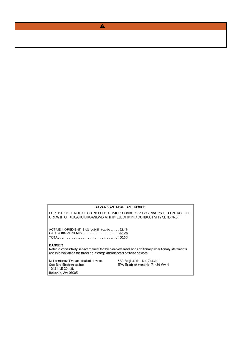
6.3 AF24173 anti-foulant device
AF24173 Anti-Foulant Devices supplied for user replacement are supplied in polyethylene bags
displaying the following label:
AF24173 ANTI-FOULANT DEVICE
FOR USE ONLY WITH SEA-BIRD ELECTRONICS' CONDUCTIVITY SENSORS TO CONTROL
THE GROWTH OF AQUATIC ORGANISMS WITHIN ELECTRONIC CONDUCTIVITY SENSORS.
ACTIVE INGREDIENT: Bis(tributyltin) oxide . . . . . 52.1%
OTHER INGREDIENTS: . . . . . . . . . . . . . . . . . . . . 47.9%
TOTAL . . . . . . . . . . . . . . . . . . . . . . . . . . . . . . . . . 100.0%
DANGER
See Precautionary Statements for additional information.
12 English

FIRST AID
If in eyes • Hold the eye open and rinse slowly and gently with water for 15–20 minutes.
• Remove contact lenses, if present, after the first 5 minutes, then continue rinsing
eye.
• Call a poison control center or doctor for treatment advice.
If on skin or clothing • Take off contaminated clothing.
• Rinse skin immediately with plenty of water for 15–20 minutes.
• Call a poison control center or doctor for treatment advice.
If swallowed • Call poison control center or doctor immediately for treatment advice.
• Have person drink several glasses of water.
• Do not induce vomiting.
• Do not give anything by mouth to an unconscious person.
HOT LINE NUMBER
Note to Physician Probable mucosal damage may contraindicate the use of gastric lavage.
Have the product container or label with you when calling a poison control center or doctor, or going for
treatment. For further information, call National Pesticide Telecommunications Network (NPTN) at
1-800-858-7378.
Net contents: Two anti-foulant devices
Sea-Bird Electronics, Inc.
13431 NE 20th St.
Bellevue, WA 98005
EPA Registration No. 74489-1
EPA Establishment No. 74489-WA-1
PRECAUTIONARY STATEMENTS
HAZARD TO HUMANS AND DOMESTIC ANIMALS
Danger:
Corrosive—Causes irreversible eye damage and skin burns. May be fatal if swallowed or absorbed
through the skin. Do not get in eyes, on skin, or on clothing. Wash thoroughly with soap and water
after handling and before eating, drinking, chewing gum, using tobacco, or using the toilet. Remove
and wash contaminated clothing before reuse.
PERSONAL PROTECTIVE EQUIPMENT
Users must wear: protective gloves (rubber or latex), goggles or other eye protection, long-sleeved
shirt, long pants, and shoes plus socks.
USER SAFETY RECOMMENDATIONS
Users should:
• Remove clothing immediately if pesticide gets inside. Then wash thoroughly and put on clean clothing.
• Follow the manufacturer's instructions for cleaning and maintaining PPE. If no such instructions for washables,
use detergent and hot water. Keep and wash PPE separately from other laundry.
ENVIRONMENTAL HAZARDS
Do not discharge effluent containing this product into lakes, streams, ponds, estuaries, oceans, or
other waters unless in accordance with the requirements of a National Pollutant Discharge
Elimination System (NPDES) permit and the permitting authority has been notified in writing prior to
discharge. Do not discharge effluent containing this product to sewer systems without previously
notifying the local sewage treatment plant authority. For guidance contact your State Water Board or
English 13

Regional Office of EPA. This material is toxic to fish. Do not contaminate water when cleaning
equipment or disposing of equipment washwaters.
PHYSICAL OR CHEMICAL HAZARDS
Do not use or store near heat or open flame. Avoid contact with acids and oxidizers.
DIRECTIONS FOR USE
It is a violation of Federal Law to use this product in a manner inconsistent with its labeling.
For use only in Sea-Bird Electronics' conductivity sensors. Read installation instructions in the
applicable Conductivity Instrument Manual.
Intended for professional use by military, government, academic, commercial, and scientific
personnel.
STORAGE AND DISPOSAL
PESTICIDE STORAGE: Store in original container in a cool, dry place. Prevent exposure to heat or flame. Do not
store near acids or oxidizers. Keep container tightly closed.
PESTICIDE SPILL PROCEDURE: In case of a spill, absorb spills with absorbent material. Put saturated
absorbent material into a labeled container for treatment or disposal.
PESTICIDE DISPOSAL: Pesticide that cannot be used according to label instructions must be disposed of
according to Federal or approved State procedures under Subtitle C of the Resource Conservation and Recovery
Act.
CONTAINER HANDLING: Nonrefillable container. Do not reuse this container for any other purpose. Offer for
recycling, if available.
6.4 China RoHS disclosure table
Name of Part Hazardous substance or element in product
Pb Hg Cd Cr(VI)) PBB PBDE
PCBs X O O O O O
Conductivity cell X O O O O O
Battery pack O O O O O O
Cables X O O O O O
Housing O O O O O O
Plumbing O O O O O O
Frame O O O O O O
Mounting hardware O O O O O O
Accessories O O O O O O
This table is compiled to the SJ/T 11364 standard.
O: This hazardous substance is below the specified limits as described in GB/T 26572.
X: This hazardous substance is above the specified limits as described in GB/T 26572.
14 English

Inhaltsverzeichnis
1 SBE 19plus V2 Kurzanleitung auf Seite 15
2 Technische Daten auf Seite 16
3 Alkalibatterien austauschen auf Seite 19
4 NiMH-Akkus aufladen auf Seite 21
5 Antifouling-Vorrichtungen auf Seite 23
6 Allgemeine Informationen auf Seite 24
Kapitel 1 SBE 19plus V2 Kurzanleitung
Diese Kurzanleitung und Bedienungsanleitung gilt für den SBE 19plus V2 SeaCAT. Das vollständige
Benutzerhandbuch mit Einzelheiten zu Einrichtung, Betrieb und Wartung finden Sie auf der Website
des Herstellers. Ausführliche Informationen zu den kursiv dargestellten Themen finden Sie im
vollständigen Benutzerhandbuch.
Im Lieferumfang enthalten:
• CD oder USB-Laufwerk mit Software, Kalibrierungsdateien und Dokumentation
• Blindstopfen und Schließringe für jeden Schottanschluss
• Daten-E/A-Kabel zum Anschließen des Sensors an einen PC
• Nichtionisches Tensid zur Reinigung des Sensor-Durchflusswegs
• Schläuche für Leitfähigkeitszelle und Aufbewahrungskit
• Ersatz-Kleinteile und Satz O-Ringe
1. Installieren Sie die vom Hersteller bereitgestellte Software auf einem PC. Weitere Informationen
finden Sie unter Software installieren.
2. Schließen Sie das Daten-E/A-Kabel an den Sensor und den PC an, und doppelklicken Sie auf
SeaTermV2.exe, um die Software zu starten.
3. Setzen Sie bei Bedarf neue Batterien ein. Einzelheiten dazu finden Sie unter Alkalibatterien
austauschen oder NiMH-Akkus aufladen.
4. Stellen Sie sicher, dass alle im Sensor gespeicherten Daten an einen PC übertragen werden.
5. Stellen Sie Datum und Uhrzeit ein, und konfigurieren Sie die Einstellungen für die
Datenerfassung.
6. Bringen Sie an nicht benutzten Schottanschlüssen Blindstopfen und Schließringe an.
7. Entfernen Sie bei Bedarf den umlaufenden Tygon® Schlauch, der die Leitfähigkeitszelle umgibt.
Dieser wird verwendet, wenn der SeaCAT eingelagert wird.
8. Verbinden Sie die Schläuche von der Pumpe mit der Leitfähigkeitszelle.
9. Senden Sie die DS- und DCal-Befehle, um Status und Kalibrierungskoeffizienten zu verifizieren.
10. Moored Mode (MM, Modus für festen Standort): Verwenden Sie StartNow, um die
Datenerfassung alle SampleInterval= x Sekunden zu starten.
11. Moored Mode (MM, Modus für festen Standort): Verwenden Sie StartDateTime= und StartLater,
um die Datenerfassung zu einem bestimmten Datum und Zeitpunkt alle
SampleInterval=Sekunden zu starten.
12. Profile Mode (MP, Profil-Modus), bei Bedarf:
• Stellen Sie den Magnetschalter in die Position Ein, oder
• Wenn IgnoreSwitch=Y, senden Sie Befehle zum Starten der Datenerfassung jetzt, mit
StartNow, oder in der zukunft, mit StartDateTime= und StartLater, um die Datenerfassung zu
einem bestimmten Datum und einer bestimmten Zeit zu starten, oder
• Wenn AutoRun=Y, schließen Sie eine externe Stromversorgung an.
13. Setzen Sie den Sensor ein. Bei den meisten Anwendungen muss sich der Anschluss unten
befinden (unterster Punkt).
14. Unmittelbar nach Einsatz des Sensors:
a. Übertragen Sie die Daten vom Sensor an einen PC. Weitere Informationen finden Sie unter
Daten übertragen.
b. Schalten Sie den Sensor aus.
Deutsch 15

c. Den Sensor mit frischem Wasser spülen.
d. Den SeaCAT zwischen den Einsätzen vor direktem Sonnenlicht schützen.
15. Weitere Informationen zur Vorbereitung des Sensors auf eine kurz- oder langfristige Lagerung
finden Sie unter Sensor für die Lagerung vorbereiten.
Kapitel 2 Technische Daten
2.1 Mechanische Daten
Gewicht, 600 m, Kunststoff, keine Pumpe, in Luft, Wasser 7,3, 2,3 kg
Gewicht, 10500 m, Titan, keine Pumpe, in Luft, Wasser 13,7, 8,6 kg
Gewicht, 5M, Kunststoff 0,3, 0,1 kg
Gewicht, 5M, Titan 0,3, 0,4 kg
Gewicht, 5T,P, Kunststoff 0,5, 0,1 kg
Gewicht, 5T, P, Titan 0,7, 0,3 kg
Nenntiefe, Acetal-Kunststoff 600 m
Nenntiefe, 3 AL–2,5 V Titan 7000 m
Nenntiefe, 6 AL–4 V 10500 m
2.1.1 Anschlüsse und Kabel
J1 zusätzlicher differentieller Eingang 0,1
Kontakt Funktion Kontakt Funktion MCBH6MP
1 Masse 4 Spannung 1 Signal
2 Spannung 0 Signal 5 Spannung 1 Masse
3 Spannung 0 Masse 6 Zusätzlicher Stromausgang
J2 zusätzlicher differentieller Eingang 2, 3
Kontakt Funktion Kontakt Funktion MCBH6MP
16 Deutsch
1 Masse 4 Spannung 3 Signal
2 Spannung 2 Signal 5 Spannung 3 Masse
3 Spannung 2 Masse 6 Zusätzlicher Stromausgang
J3 Daten E/A, Pumpe, externe Stromversorgung
Kontakt Funktion Kontakt Funktion MCBH6MP
1 Masse 4 Pumpenversorgung Masse
2 RS232 Daten RX 5 Pumpenversorgung
3 RS232 Daten TX 6 Zusätzlicher Stromeingang, 9 - 28 V
DC
J4 zusätzlicher differentieller Eingang 4, 5
Kontakt Funktion Kontakt Funktion MCBH6MP
1 Masse 4 Spannung 5 Signal
2 Spannung 4 Signal 5 Spannung 5 Masse
3 Spannung 4 Masse 6 Zusätzlicher Stromausgang
J5 zusätzlicher serieller Eingang
Sensor und 19plus müssen auf die gleiche Baudrate eingestellt sein
Kontakt Funktion MCBH4MP
1 Masse
2 RS232 Datenübertragung an RS232 Sensor
3 RS232 Datenempfang von RS232 Sensor
4 Stromversorgung für RS232 Sensor
Abbildung 1 Y-Kabel
Deutsch 17
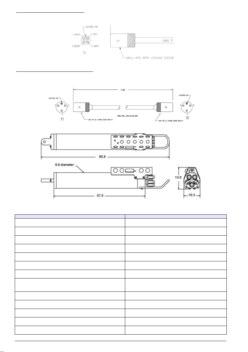
Abbildung 2 Daten-E/A-Kabel
Abbildung 3 SBE 5 an CTD-Kabel
2.1.2 Abmessungen
2.2 Elektrik und Kommunikation
Eingang von externer Stromversorgung 9 - 28 V DC
Stromaufnahme von externer Stromversorgung, 5M 3 A bei 9 V, 0,5 A bei 12 V und 19 V
Stromaufnahme von externer Stromversorgung, 5T, 5P 3 A bei bei 12 V, 1,5 A bei 19 V
Stromaufnahme, Datenerfassung 70 mA
Stromaufnahme, 5M Pumpe 100 mA
Stromaufnahme, 5T, 5P 150 mA
Stromaufnahme, Kommunikation 65 mA
Stromaufnahme, geringe Leistung (betrieben mit internen
Batterien)
20 µA
Interne Batteriekapazität, 9 Alkali-D-Zellen 14 Ah
Interne Batteriekapazität, NiMH-Akkupack 8 Ah
Zusätzlicher Stromausgang bei 10,5 - 11 V DC bis 500 mA
Spannung Auflösung A/D 14 Bit
Spannung Sensor-Eingangsbereich 0 - 5 V DC
18 Deutsch

Speicher 64 MB Flash
Kommunikationsschnittstelle RS232
Datenerfassungsrate 4 Hz
2.3 Analytische Daten
Parameter Messbereich Genauigkeit Stabilität Lösung
Leitfähigkeit 0 - 9 ±±0,005 V 0,0003 S/m pro Monat 0,00007 S/m
Temperatur -5 - 35 °C ±0,005 V 0,0002 °C/Monat 0,0001 °C
Druck-/Dehnun
gsmessgerät
verschieden bis
10.500 m
±0,1 % des
Messbereich-
Endpunkts
±0,1 % des Messbereich-
Endpunkts
0,002 % des
Messbereich-
Endpunkts
Druck, Quarz verschieden bis
10.500 m
±0,02 % ±0,02 % 0,0025 % des
Messbereich-
Endpunkts
Kapitel 3 Alkalibatterien austauschen
WARNUNG
Wenn der Benutzer der Meinung ist, dass sich Wasser im Druckgehäuse des Sensors befindet, den
Sensor von der Stromversorgung trennen. Setzen Sie eine Sicherheitsbrille auf, und stellen Sie
sicher, dass der Sensor von Ihrem Körper und anderen Personen weg zeigt. Verwenden Sie den
Auslass (sofern der Sensor über einen solchen verfügt) in einem gut belüfteten Bereich, oder
lockern Sie den Schottanschluss ganz LANGSAM, damit der Druck entweichen kann.
WARNUNG
Wenn der Benutzer der Meinung ist, dass die Alkali-Batterien undicht sind, hat sich möglicherweise
Druck im Druckgehäuse aufgebaut. Befolgen Sie die ESD-Protokolle, um den Innendruck
abzulassen. Tragen Sie eine Sicherheitsbrille und Schutzhandschuhe, und stellen Sie sicher, dass
der Sensor von Ihrem Körper und anderen Personen weg zeigt. Lockern Sie in einem gut belüfteten
Bereich ganz LANGSAM den Schottanschluss, damit der Druck entweichen kann. Von Wärme,
Funken, Flammen und anderen Zündquellen fernhalten. Nicht rauchen.
VORSICHT
Das Druckgehäuse enthält gegen elektrostatische Entladung (ESD) empfindliche Teile und
Baugruppen, die durch ESD beschädigt werden können. Befolgen Sie die ESD-Protokolle:
• Tragen Sie einen Augenschutz, wenn Sie das Druckgehäuse öffnen.
• Elektrostatische Ladungen am Körper des Bedieners müssen vor dem Öffnen des
Druckgehäuses abgeleitet werden: Legen Sie eine Hand auf eine geerdete Oberfläche, oder
besser: Tragen Sie ein geerdetes Antistatikband.
• Tragen Sie für diese Wartungstätigkeit mindestens kurzärmelige antistatische Kleidung, z.B. aus
Baumwolle, oder besser einen antistatischen Kittel. Tragen Sie keine Pullover, Fleece- oder
Polyesterkleidung.
• Verwenden Sie mindestens eine Arbeitsstation mit einer Tischplatte aus Holz oder Metall oder
besser eine Tischplatte, die statische Elektrizität ableitet. Arbeiten Sie nicht auf einer Tischplatte
aus Synthetik- oder Polymermaterial.
1. Die Außenseite des Batterie-Endflansches mit einem sauberen Tuch abtrocknen. Gegebenenfalls
Wasser zwischen dem Druckgehäuse und dem Endflansch vollständig entfernen.
2. Mithilfe eines Schraubenschlüssels an der weißen Kunststoffschiene den Endflansch gegen den
Uhrzeigersinn drehen, um ihn zu lösen.
Deutsch 19
3. Gegebenenfalls Wasser auf den O-Ring-Oberflächen mit einem fusselfreien Tuch oder
Papiertuch vollständig entfernen.
4. Den Endflansch sauber halten und den O-Ring vor Verschmutzung oder Beschädigung schützen.
5. Die drei Kreuzschlitzschrauben und Unterlegscheiben von der Batterieabdeckung entfernen.
Die Batterieabdeckung löst sich.
6. Nehmen Sie die Batterien aus dem Messgerät.
7. Legen Sie neue Batterien ein. Achten Sie darauf, dass der + Pol sich an der flachen Kontaktseite
und der - Pol sich auf der Kontaktseite mit der Feder befindet.
8. Richten Sie die Batterieabdeckung am Gehäuse aus. Die Bolzen im Gehäuse sind asymmetrisch,
sodass die Abdeckung nur in einer Ausrichtung auf das Gehäuse passt.
Eine Schraubenöffnung befindet sich näher am Rand als die anderen und passt zu dem Bolzen,
der am nächsten zum Gehäuse liegt.
9. Setzen Sie alle drei Kreuzschlitzschrauben und Unterlegscheiben wieder ein: Drücken Sie fest
auf die Abdeckung und achten Sie darauf, dass die Feder richtig an den Batterien anliegt.
Stellen Sie sicher, dass die Schrauben fest angezogen sind, anderenfalls ist die Batterieleistung
nicht zuverlässig.
10. Überprüfen Sie, ob die Batteriespannung an BAT + und BAT - an der Batterieabdeckung etwa
18 V entspricht.
11. Stellen Sie sicher, dass alle O-Ring-Oberflächen sauber und trocken sind. Tauschen Sie die O-
Ringe bei Bedarf aus.
12. Tragen Sie eine dünne Schicht Parker Super O Lube auf Silikonbasis auf die aneinander
liegenden O-Ring-Flächen auf.
13. Setzen Sie den Endflansch vorsichtig auf das Gehäuse und schrauben Sie ihn fest. Stellen Sie
mithilfe eines Schraubenschlüssels sicher, dass die Kappe fest montiert ist.
14. Überprüfen Sie, ob der Schalterstößel herausgezogen ist, sodass sich der Searam in einem
Modus mit geringerer Spannung befindet.
20 Deutsch
Table of contents
Languages:
Other Sea-Bird Scientific Accessories manuals


