manuals.online logo
Brands
  1. Home
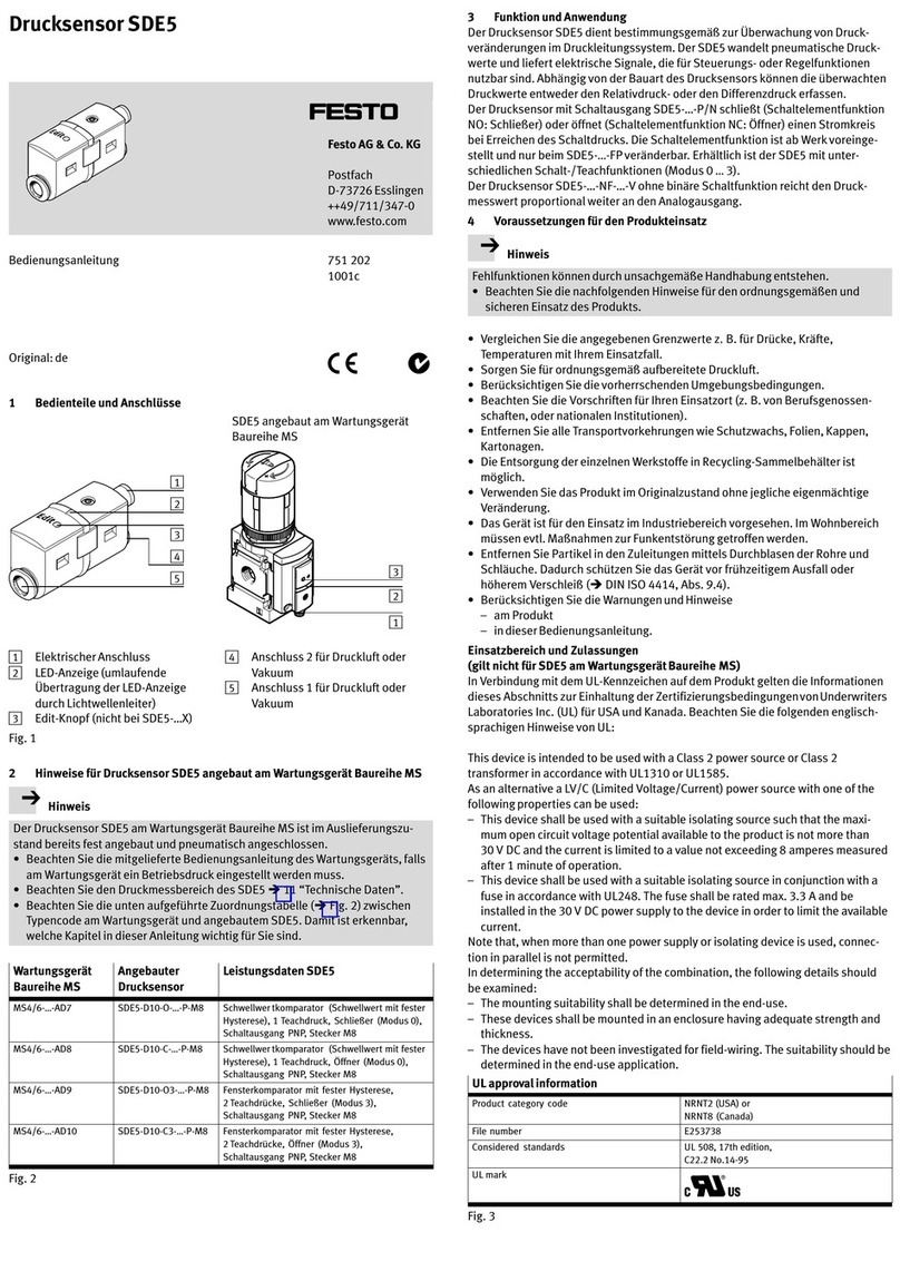
  2. •
  3. Brands
  4. •
  5. Festo
  6. •
  7. Accessories
  8. •
  9. Festo SRBG User manual

Festo SRBG User manual

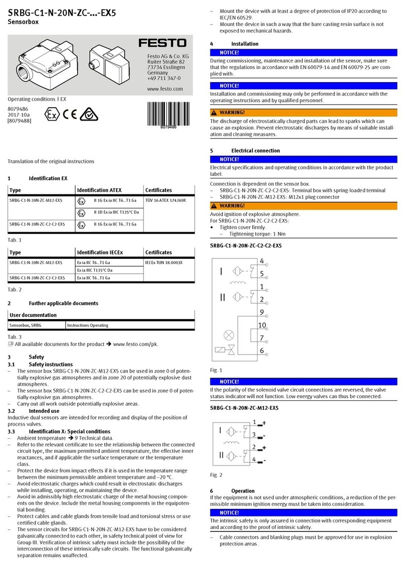
Sensor box
SRBG
Festo AG & Co. KG
Ruiter Straße 82
73734 Esslingen
Germany
+49 711 347-0
www.festo.com
Operating instructions
(Original instructions)
8075401
2017-07a
[8075403]
Sensor box SRBG English..............................................
1 Configuration
1.1 SRBG-…-C2-C2
4
2
5
6
1
7
8
3
1Housing cover
2Housing screws
3Yellow LED, switching status indic
ation for solenoid valve
4Caged spring terminal
5Cable entry M20 x 1.5 for system
connection
6Cable entry M12 x 1.5 for solenoid
valve connection
7Inductive dual sensor
8Green LED, power supply indicator
(only for SRBG-C1-N-1-P-C2-C2)
yellow LED, switching status indic
ation
Fig. 1
1.2 SRBG-…-M12
3
1
2
1Green LED, power supply indicator
(only for SRBG-C1-N-1-P-M12)
Yellow LED, switching status indic
ation
2Inductive dual sensor
3M12 plug connection
Configuration of SRBG-…-M12-M12 (èChapter 4.2)
Accessories èwww.festo.com/catalogue.
2 Safety
The sensor box is intended for recording, electrical feedback and optical display of
the end positions of drives.
Appropriate for operation are semi-rotary drives with a mechanical interface in
accordance with VDI/VDE Directive 3845.
– The product may only be used in its original status.
– Only use the product if it is in an excellent technical status.
– Observe the product labelling.
– If cable connector the O-ring supplied is not necessary.
3 Function
The sensor box SRGB detects the end position of the drive with the help of the
SASF position indicator as an activating element. Inductive sensors of the sensor
box detect the metallic actuating elements on the position indicator in a
non-contact manner. These actuating elements are fixed at an offset of 90° and
are suitable for anti-clockwise and clockwise drives with a 90° or 180° rotation
angle.
4 Installation and commissioning
Warning
Electric voltage.
Injury due to electric shock.
 Switch off the power supply before opening the device.
Note
Installation and commissioning should only be conducted by qualified personnel.
4.1 Mechanical
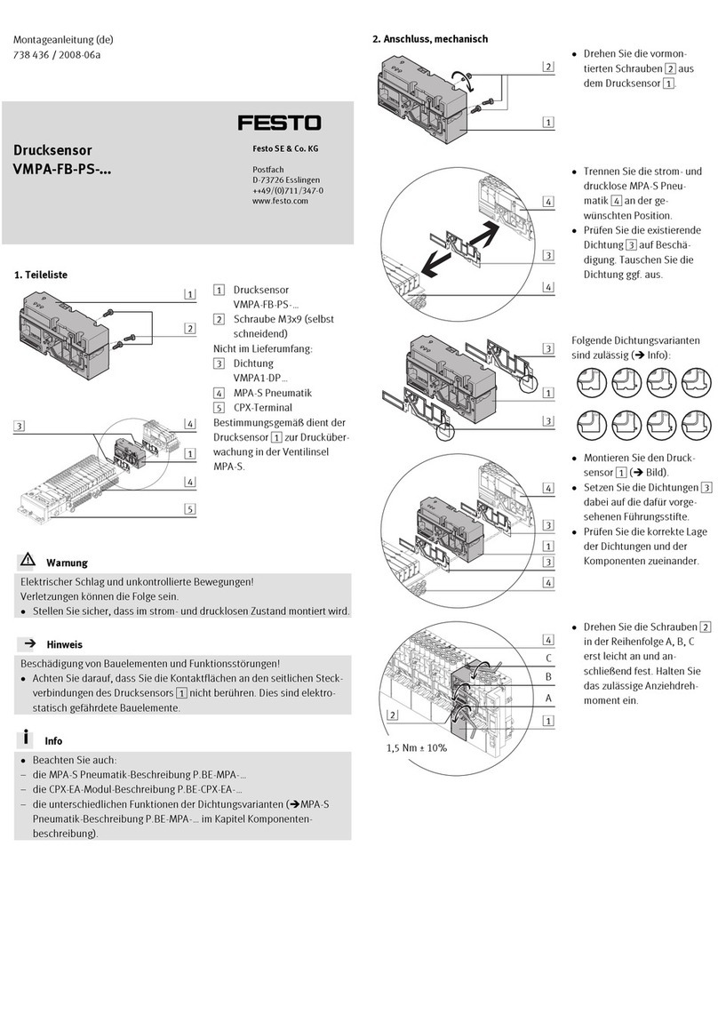
Mount the sensor box to the fastening interface of the semi-rotary drive. Use M5
mounting screws. The mounting holes in the sensor housing ensure that no adjustment
is necessary when mounting the sensor. Attach the SASF position indicator to the drive
shaft. Use M6 screws. Use a spacer disc, dependent on the wave height. When mount
ing is complete, attach the stopper cap and identification stopper to the position indic
ator.
1
2
3
4
1Stopper cap
2Identification stopper
3Actuating elements
4Spacer disc
Fig. 2
4.2 Electrical
Note
Inappropriate cables or incorrect installation reduce the degree of protection
of the sensor box.
Note
The product is suitable for industrial purposes only. This product can generate
high frequency interference, which may make it necessary to implement interfer
ence suppression measures in residential areas.
Note
Coupling powerful electromagnetic fields of 3 V can cause the product to mal
function at an operating frequency between 500 and 600 kHz.
Connection SRBG-…-C2-C2
1. Loosen the housing screws 2on the housing cover. Remove the housing cover.
2. Screw the cable connector into the cable entry. Guide the electric connecting
cable through the cable connector to the terminal block.
– Conductor cross section: 1.5/2.5 mm2(flexible/rigid).
3. Seal unused cable entries with blanking plugs.
4. Wire the connections (èproduct labelling).
5. Place the housing cover in position and tighten the 4 housing screws 2.
Connection SRBG-C1-N-1-AS-M12-M12 / SRBG-…-M12
12
3
4
5
6
1SRBG-…-M12-M12:
Solenoid valve connection
2SRBG-…-M12-M12:AS-i connection
SRBG-…-M12: sensor connection
3Yellow LED,
witching status indication
4Green LED, power supply indicator
5Switching status indication
6SRBG-…-M12-M12: Switching
status indication for solenoid valve
Programming instructions
Adress 00 preset, can be changed via bus master or programming units
IO code D
Ident. code A
ID1 code 7
ID2 code E
Data bit
Bit Function
D0 Valve status / (0=valve off, 1=valve on)
D1 Valve error1) /(0=wire break/short circuit; 1=no error)
D2 Switching output sensor 12) /(0=attenuated; 1=uncushioned)
D3 Switching output sensor 22) /(0=attenuated; 1=uncushioned)
Parameter bit
Bit Function
P0 Watchdog (0=inactive; 1=active)3)
P1 Switching element function sensor 24) /(0=N/O contact; 1= N/C contact)
P2 Switching element function sensor 14) / (0=N/O contact; 1= N/C contact)
P3 Not used
1) Check only with activated valve (D0=1)
2) Applies to N/C function (P2/P3=1; preset), reversed behaviour with N/O function (P2/P3=0)
3) Watchdog active: Valve voltage drops in the event of AS-Interface communication error
4) Presetting: N/C contact
5 Maintenance and care
If used as intended, the product is maintenance-free.
6 Technical data
Position indicator SASF SASF-S2-B-F-A34 SASF-S2-B-F-A56
Ring diameter [mm] 65 110
Circlip height [mm] 6 7
Ambient temperature [°C] -25 … 80
Mechanical data
Shaft diameter [mm] 58 90
Shaft height [mm] 20/30 30/50
Mounting hole pattern [mm] 30x80 30x130
Material
Housing, Spacer disc, Identification
stopper
PBT
Stopper cap PP
Mounting screw, Actuating lug high-alloy stainless steel
Hinweis
The plastic housings of the position indicator are made of conductive material
and must be integrated into a suitable earthing concept.
Hinweis
The position indicator SASF consists of conductive plastic material.
 Use in potentially explosive areas possible, as there is no static charge.
SRBG-…-M12-M12
Switching output AS-Interface
Switching element function Programmable N/O contact/ N/C contact
Max. switching frequency [Hz] 100
Idle current [mA] 35
Operating voltage range DC
AS-Interface
[V] 26.5 … 31.6
Load voltage range DC [V] 21.6 … 26.4
Current consumption with load
voltage from AS-Interface and
load voltage connection
[mA] 100
Protocol AS-Interface specification V3.0 Required master spe
cification ≥ V2.1 Slave type A/B slave
Device-specific diagnostics Wire break/short circuit in valve
Addressing range 1A … 31A (0) / 1B … 31B
Reverse polarity protection for all electrical connections
Sensor connection M12 x 1, plug, 4-pin
Ambient temperature [°C] -25 … 70
Storage temperature [°C] -25 … 70
Degree of protection IP67
Shock resistance Shock test with severity level 2 to FN 942017-5 and
EN 60068-2-27
Vibration resistance Transport application test with severity level 2 to FN
942017-4 and EN 60068-2-6
CE marking in accordance with EU EMC Directive
Approval c UL us (OL) RCM compliance mark
Housing PBT
M12 plug, Screws high-alloy stainless steel
Note on materials RoHS compliant / Contains paint-wetting impairment
substances
Mounting position any
SRBG-…-M12/SRBG-…-C2 -P -ZU -ZC
Switching output PNP non-contacting, 2-wire NAMUR
Switching element function N/O contact N/O contact N/C contact
Max. switching
frequency
[Hz] 500 500 3000
Operating voltage range [V DC] 10 … 30 6 … 60 8.2
Max. output current DC [mA] 100 100 3
Voltage drop [V] 3 6 -
Idle current [mA] 25 - -
Residual current [mA] 0.5 1 -
Minimum load current [mA] - 4 -
Reverse polarity protection for all electrical connections
Switching status indication Yellow LED
Power supply indicator Green LED - -
Sensor connection
SRBG-…-M12
M12 x 1, plug, 4-pin
Electrical connection
SRBG-…-C2
spring-loaded terminal
Ambient temperature [°C] -25 … 70 -25 … 70 -25 … 100
Storage temperature [°C] -25 … 70 -25 … 70 -40 … 100
Degree of protection IP67
Shock resistance Shock test with severity level 2 to FN 942017-5 and
EN 60068-2-27
Vibration resistance Transport application test with severity level 2 to FN
942017-4 and EN 60068-2-6
CE marking in accordance with EU EMC Directive
  in accordance
with ATEX
Approval c UL us (OL) RCM compliance mark
Housing PBT
M12 plug, Screws high-alloy stainless steel
Note on materials RoHS compliant / Contains paint-wetting impairment sub
stances
Mounting position any
This manual suits for next models

3

Other Festo Accessories manuals

Festo SOPA-C series User manual

Festo

Festo SOPA-C series User manual

Festo SFAW User manual

Festo

Festo SFAW User manual

Festo SOOE-RS PNLK-T Series User manual

Festo

Festo SOOE-RS PNLK-T Series User manual

Festo SDBT-MSX Parts list manual

Festo

Festo SDBT-MSX Parts list manual

Festo SDAT-MHS User manual

Festo

Festo SDAT-MHS User manual

Festo SRBC Series User manual

Festo

Festo SRBC Series User manual

Festo SDE5 series User manual

Festo

Festo SDE5 series User manual

Festo SFAM User manual

Festo

Festo SFAM User manual

Festo SFAB-PNLK Series User manual

Festo

Festo SFAB-PNLK Series User manual

Festo MS6-SFE-F5-AGD Series User manual

Festo

Festo MS6-SFE-F5-AGD Series User manual

Festo VMPA-FB-PS Series User manual

Festo

Festo VMPA-FB-PS Series User manual

Festo SDE3 series User manual

Festo

Festo SDE3 series User manual

Festo SBSi User manual

Festo

Festo SBSi User manual

Festo Span Series User manual

Festo

Festo Span Series User manual

Festo PEV-1/4A-WD User manual

Festo

Festo PEV-1/4A-WD User manual

Festo SDE5 series User manual

Festo

Festo SDE5 series User manual

Festo ASLR-D-L1 User manual

Festo

Festo ASLR-D-L1 User manual

Festo SOPA Series User manual

Festo

Festo SOPA Series User manual

Festo Sorting Station Inline User manual

Festo

Festo Sorting Station Inline User manual

Festo SDE1 Series User manual

Festo

Festo SDE1 Series User manual

Festo SOPA User manual

Festo

Festo SOPA User manual

Festo SFAM-62 User manual

Festo

Festo SFAM-62 User manual

Festo SPAE User manual

Festo

Festo SPAE User manual

Festo CP Lab User manual

Festo

Festo CP Lab User manual

Popular Accessories manuals by other brands

Optex Prosafe OA-1V Operation manual

Optex

Optex Prosafe OA-1V Operation manual

Maxcess FIFE DSE-31 operating instructions

Maxcess

Maxcess FIFE DSE-31 operating instructions

Wieland sensorPRO STS installation instructions

Wieland

Wieland sensorPRO STS installation instructions

SkyLink HA-318T user manual

SkyLink

SkyLink HA-318T user manual

JBL Cooler 100 Important instructions

JBL

JBL Cooler 100 Important instructions

ULTIMATE SPEED UPBS 12000 A1 Operation and safety notes

ULTIMATE SPEED

ULTIMATE SPEED UPBS 12000 A1 Operation and safety notes

ORION TELESCOPES & BINOCULARS EZ Finder Deluxe II instruction manual

ORION TELESCOPES & BINOCULARS

ORION TELESCOPES & BINOCULARS EZ Finder Deluxe II instruction manual

Jocel JAG003447 instruction manual

Jocel

Jocel JAG003447 instruction manual

Grizzly G5938 instructions

Grizzly

Grizzly G5938 instructions

Joycare JC-637 quick start guide

Joycare

Joycare JC-637 quick start guide

Slazenger S000154 Assembly, Installation, Care, Maintenance, and Use Instructions

Slazenger

Slazenger S000154 Assembly, Installation, Care, Maintenance, and Use Instructions

Hobo S-LIA-M003 manual

Hobo

Hobo S-LIA-M003 manual

Datalogic Smart-VS Product reference guide

Datalogic

Datalogic Smart-VS Product reference guide

Endress+Hauser OUSAF46 operating instructions

Endress+Hauser

Endress+Hauser OUSAF46 operating instructions

Lacerta M-GEN user manual

Lacerta

Lacerta M-GEN user manual

Panasonic ET-PNT100 operating instructions

Panasonic

Panasonic ET-PNT100 operating instructions

Sam SAMX DRAINER manual

Sam

Sam SAMX DRAINER manual

TASC 2 Series user manual

TASC

TASC 2 Series user manual

manuals.online logo
manuals.online logoBrands
  • About & Mission
  • Contact us
  • Privacy Policy
  • Terms and Conditions

Copyright 2025 Manuals.Online. All Rights Reserved.