Sea-Bird Scientific SBE 37 MicroCAT User manual

User manual
SBE 37 MicroCAT
Conductivity and temperature sensor (optional
pressure and optical dissolved oxygen)
Document No. 37 SM, SMP,
SMP-ODO
Release Date: 2023-01-05
Version: A
Software: Seasoft V2
425-643-9866
seabird.com


Table of Contents
Section 1 Safety information............................................................................................................ 3
1.1 Hazard information....................................................................................................................... 3
1.2 Equipment labels.......................................................................................................................... 4
Section 2 MicroCAT quick start guide........................................................................................... 5
Section 3 Specifications.................................................................................................................... 7
3.1 Feature summary......................................................................................................................... 7
3.2 Mechanical................................................................................................................................... 7
3.2.1 Bulkhead connector.............................................................................................................7
3.2.2 Dimensions..........................................................................................................................8
3.3 Electrical....................................................................................................................................... 9
3.4 Communications.......................................................................................................................... 9
3.5 Analytical...................................................................................................................................... 9
Section 4 Overview........................................................................................................................... 11
4.1 Operation................................................................................................................................... 11
4.2 Sample times............................................................................................................................. 12
4.3 Battery life.................................................................................................................................. 12
4.4 Cable length and external power............................................................................................... 13
Section 5 Set up sensor and verify operation............................................................................ 15
5.1 Verify anti-fouling devices.......................................................................................................... 15
5.2 Install batteries........................................................................................................................... 16
5.3 Install software and test sensor.................................................................................................. 18
5.3.1 Software menu items.........................................................................................................19
5.3.2 Communication troubleshooting........................................................................................ 19
5.4 Set up pump............................................................................................................................... 20
5.4.1 Set up pump for ODO accuracy........................................................................................ 20
Section 6 Deployment and recovery.............................................................................................23
6.1 Data collection modes................................................................................................................ 25
6.1.1 Autonomous mode............................................................................................................ 25
6.1.2 Polled (controlled) mode................................................................................................... 26
6.1.3 Serial line sync mode........................................................................................................ 27
6.2 Default output format ................................................................................................................. 28
6.2.1 Other data formats............................................................................................................ 29
6.2.1.1 XML data format....................................................................................................... 29
6.2.1.2 Alternate output format ............................................................................................ 30
6.2.1.3 SDI-12 output format ............................................................................................... 31
6.2.1.4 Diagnostic data format............................................................................................. 31
6.3 Transmit real-time data.............................................................................................................. 32
6.4 Recover sensor from deployment.............................................................................................. 33
Section 7 Transmit and convert data........................................................................................... 35
7.1 Transmit data to PC................................................................................................................... 35
7.2 Convert data............................................................................................................................... 36
Section 8 Maintenance..................................................................................................................... 39
8.1 Plastic sensor maintenance....................................................................................................... 39
8.2 Remove or replace anti-fouling devices..................................................................................... 39
8.3 Clean flow path.......................................................................................................................... 40
8.4 Maintain pump............................................................................................................................ 41
8.5 Clean pressure sensor............................................................................................................... 41
8.6 Examine O-rings........................................................................................................................ 42
8.7 Clean bulkhead connectors........................................................................................................ 42
1

8.8 CTD storage............................................................................................................................... 43
8.9 Calibration.................................................................................................................................. 44
8.9.1 Conductivity....................................................................................................................... 44
8.9.2 Temperature...................................................................................................................... 44
8.9.3 Pressure............................................................................................................................ 44
8.9.4 Optical Dissolved Oxygen................................................................................................. 44
8.10 Spare parts and accessories.................................................................................................... 45
8.10.1 SBE 37 spare hardware and O-ring kit............................................................................45
Section 9 Reference: command descriptions............................................................................ 47
9.1 Status......................................................................................................................................... 47
9.2 General setup............................................................................................................................. 50
9.3 Pump setup................................................................................................................................ 51
9.4 Memory setup............................................................................................................................ 51
9.5 Output format setup................................................................................................................... 52
9.6 Autonomous operation with data storage................................................................................... 52
9.7 Polled data collection, model without pump............................................................................... 53
9.8 Polled data collection, models with pump.................................................................................. 53
9.9 Serial line synchronization......................................................................................................... 54
9.10 Data upload.............................................................................................................................. 54
9.11 Calibration coefficients............................................................................................................. 54
9.12 ODO setup............................................................................................................................... 56
9.13 Dissolved oxygen coefficients.................................................................................................. 56
9.14 SDI-12 commands and output................................................................................................. 57
9.14.1 Measurement commands................................................................................................ 58
9.14.2 SDI-12 extended commands........................................................................................... 60
Section 10 Troubleshooting........................................................................................................... 63
10.1 No communications with sensor.............................................................................................. 63
10.2 No data recorded..................................................................................................................... 63
10.3 Data looks incorrect................................................................................................................. 63
10.4 Salinity spikes.......................................................................................................................... 63
Section 11 General information..................................................................................................... 65
11.1 Warranty................................................................................................................................... 65
11.2 Service and support................................................................................................................. 65
11.3 Lithium battery shipment.......................................................................................................... 65
11.4 AF24173 anti-foulant device.................................................................................................... 66
11.5 China RoHS disclosure table................................................................................................... 68
Table of Contents
2
Section 1 Safety information
Please read this entire manual before this equipment is unpacked, set up, or operated.
Pay attention to all danger, warning, and caution statements. Failure to do so could result
in serious injury to the operator or damage to the equipment.
DANGER
Indicates a potentially or imminently hazardous situation which, if not avoided, will result in death
or serious injury.
WARNING
Indicates a potentially or imminently hazardous situation which, if not avoided, could result in
death or serious injury.
CAUTION
Indicates a potentially hazardous situation that may result in minor or moderate injury.
NOTICE
Indicates a situation which, if not avoided, may cause damage to equipment. Information that
requires special emphasis.
1.1 Hazard information
WARNING
If the user thinks that the lithium batteries have leaks, pressure may have built up inside
of the pressure housing. Follow ESD protocols to release internal pressure. Put on
safety glasses and protective gloves and make sure that the sensor is pointed away
from the body and other people. In a well ventilated very SLOWLY loosen the bulkhead
connector to release the pressure. Keep away from heat, sparks, flame, and other
sources of ignition. Do not smoke.
CAUTION
The pressure housing contains Electrostatic Discharge (ESD) sensitive parts and
assemblies that are susceptible to damage from ESD. Follow ESD protocols:
• Put on protective eye wear before you open the pressure housing.
• Any electrostatic charge on the body of the human operator must be released
before the pressure housing is opened: put a hand on a grounded surface, or
better, wear a grounded antistatic wrist strap.
• At a minimum, wear short-sleeved antistatic clothing, such as cotton, or better,
wear an antistatic smock for this service activity. Do not wear a sweater, fleece or
polyester-based clothing.
• At a minimum, use a workstation with a wood or metal tabletop, or better, a
tabletop that dissipates static. Do not use a workstation with a synthetic or
polymeric-based tabletop.
CAUTION
AF24173 anti-fouling devices contain bis(tributyltin) oxide. Wear rubber or latex gloves and eye
protection to replace these devices on the sensor if it is so equipped. Wash hands with soap and
water when finished.
Read the precautions on the product label.
It is a violation of US federal law to use this product in a manner that is inconsistent with its label.
3

NOTICE
The manufacturer is not responsible for any damages due to misapplication of misuse of this
product including, without limitation, direct, incidental and consequential damages, and disclaims
such damages to the full extent permitted under applicable law. The user is solely responsible to
identify critical application risks and install appropriate mechanisms to protect process during a
possible equipment malfunction.
1.2 Equipment labels
Read all labels and tags attached to the equipment. Personal injury or damage to the
equipment could occur if not observed. A symbol on the equipment is referenced in the
manual with a precautionary statement.
Electrical equipment marked with this symbol may not be disposed of in European domestic or public disposal
systems. Return old or end-of-life equipment to the manufacturer at no charge to the user.
ATTENTION!
Remove sticker before deployment!
This sticker protects your instrument during shipping. REMOVE BEFORE DEPLOYMENT;if it is not removed,
your instrument will not operate properly and you may cause severe damage to the conductivity cell. The
conductivity cell is made of glass and will break if mishandled or frozen while filled with water. Apply new sticker
to protect instrument when not in use (see spares kit).
NOTICE: Sticker may have come in contact with the AF24173 Anti-foulant device, which contains TBTO.
Dispose of the removed sticker' see MSDS for handling precautions.
Safety information
4

Section 2 MicroCAT quick start guide
This quick start guide gives the steps necessary to make sure that the SBE 37 MicroCat
sensor operates correctly and collects data before it is deployed.
This quick start guide and user manual applies to SBE 37 SM, SBE 37 SMP, and SBE
37 SMP-ODO models. Refer to Feature summary on page 7 for more details about
each model.
What's in the box:
• CD or USB drive—has software, calibration files, documentation
• Dummy plug and lock collar
• Data I/O cable to connect the sensor to a PC
• Plumbing kit and non-ionic surfactant to clean sensor flow path
• Spare hardware and O-ring kit.
1. Install the manufacturer-supplied batteries. Refer to Install batteries on page 16 for
details.
a. Remove the end flange of the sensor.
b. Disconnect the battery holder and remove it from the sensor.
c. Install new batteries.
d. Connect the battery pack to the sensor again and install the end flange again.
2. Install the manufacturer-supplied software on a PC. Refer to Install software and test
sensor on page 18for details.
3. Connect the data I/O cable to the sensor and the PC and double-click on
SeatermV2.exe to start the software.
4. Set up the sensor for deployment. Refer to Set up sensor and verify operation
on page 15 for details.
a. If necessary, make sure that all data stored in the sensor is transmitted to a PC.
b. Set the date and time and configure the data collection settings.
c. Send the DS and DC commands to verify setup.
d. For RS232 deployments:
• use StartNow to start data collection every SampleInterval= x seconds.
• use StartDateTime= and StartLater to start data collection at a specified date
and time, every SampleInterval=seconds.
5. Remove the yellow protective label from the plumbing intake and exhaust.
6. Verify that the antifouling devices are installed. Refer to Verify anti-fouling devices
on page 15for details.
7. Connect the data I/O cable to the sensor and a PC.
8. Deploy the sensor. For most applications, make sure the connector is at the bottom
(lowest point).
9. Immediately after the sensor is recovered from a deployment:
a. Transmit data from the sensor to a PC. Refer to Transmit and convert data
on page 35 for details.
b. Use the software to turn off the sensor.
c. Flush the sensor with fresh water.
d. Keep the sensor out of direct sunlight between deployments
10. Refer to CTD storage on page 43 for details to prepare the sensor for short- or long-
term storage.
5

MicroCAT quick start guide
6

Section 3 Specifications
3.1 Feature summary
Model Hardware options Communication options
(RS232 is standard)
Pressure Internal
batteries
Pump Optical
Dissolved
Oxygen
RS485 SDI-12 Integrated
Inductive
Modem
37-SM X X X
37-SMP X X X X or X
37-SMP-ODO X X X X X or X
37-SI X X
37-SIP X X X
37-IM X X X
37-IMP X X X X
37-IMP-ODO X X X X X
Abbreviation key:
• S = serial communication
• I = internal memory
• M = memory
• P = pump
• IM = inductive modem
• ODO = optical dissolved oxygen
3.2 Mechanical
Weight, 350 m, plastic Weight, 7000 m, titanium Length
37-SM 2.4, 1.1 kg 3.3, 1.5 kg 44.68 cm
37-SMP 3.4, 1.6 kg 3.7, 2.2 kg 53.52 cm
37-SMP-ODO 3.3, 1.5 kg 4.4, 2.5 kg 53.52 cm
3.2.1 Bulkhead connector
Contact Function MCBH-4-MP
1 Ground
2 RS232 RX
3 RS232 TX
4 Voltage in
7

3.2.2 Dimensions
37 SM
37 SMP
Specifications
8

37 SMP-ODO
3.3 Electrical
Input 9–24 VDC
Current draw, operation 0.29 watts
Current draw, low power 30 µA
Current draw, communication 4.3 mA
3.4 Communications
Memory 8 Mb
Communication interface RS232
RS232 output rate user-selectable, 600–115200 baud (default 19200)
Data collection rate 1 Hz
37-SM data storage 530000 samples
37-SMP data storage 425000 samples
37-SMP-ODO data storage 25000 samples
3.5 Analytical
Parameter Range Accuracy Stability Resolution
Conductivity 0–70 mS/cm ±0.003 mS/cm 0.003 mS/cm/mo 0.0001 mS/cm
Temperature -5–45 °C ±0.002 °C (-5–35 °C) 0.0002 °C/mo 0.0001 °C
Pressure not more than the SBE
37 rated depth
±0.1% full scale range 0.05% full scale range/yr 0.002% full scale range
Specifications
9

Specifications
10

Section 4 Overview
4.1 Operation
The SBE 37 MicroCAT measures conductivity (C) and temperature (T).
Optional equipment includes:
• Pressure (depth, D)
• Internal pump
• Optical Dissolved Oxygen (ODO)
The sensor can operate as a standalone or is easily integrated with other platforms.
The optional internal pump operates for one second each time the sensor collects a
sample. The internal pump has several advantages over sensors without pumps:
• The pump flushes the water from the flow path after each sample and quickly moves
a new sample into the flow path so that conductivity and oxygen measurements are
more accurate.
• Water does not flow freely through the flow path so it stays saturated with the anti-
fouling chemicals.
• The ODO sensor (SMP-ODO only) is integrated in the flow path to better align with
the CTD measurement.
The user can operate the sensor in one of several modes:
Autonomous
• Operates at user-selected intervals (6–21600 seconds).
• Transmits data real-time if TxRealTime=Y.
• Not compatible with SDI-12.
• Operation sequence:
1. The pump operates for one second (uses MinCondFreq=)
2. The sensor makes one measurement
3. The data is stored internally
4. The sensor goes into a low power mode until the next sample is collected.
Serial Line Synchronization
• Responds to a pulse on the serial line.
• Transmits data real-time if TxRealTime=Y.
• Not compatible with SDI-12.
• Operation sequence:
1. The pump operates for one second (uses MinCondFreq=)
2. The sensor makes one measurement
3. The data is stored internally
4. The sensor goes into a low power mode until the next sample is collected.
Polled operation
• Polled data collection is useful when the sensor is integrated with satellite, radio, or
wire telemetry equipment.
• Operation sequence:
1. The pump operates on command for one second
2. The sensor makes one measurement
3. The sensor sends the data to the controller
4. The sensor goes into a low power mode until the next command to operate.
There are two ways to deploy the sensor:
11

1. Cable installed—the sensor is controlled remotely and transmits data on command.
The sensor can also operate autonomously and transmit data at a user-set interval.
Data can be transmitted while the sensor is deployed.
2. Dummy plug installed—the interval at which data is collected is set by the user before
deployment. Data is transmitted to a PC after deployment.
4.2 Sample times
The time it takes for the MicroCAT to collect a sample depends on several factors, such
as the data collection mode, and whether the optional pressure sensor is installed. Data
collection time does not include the time it takes to transmit real-time data, which
depends on the baud rate and the number of characters transmitted.
The time that shows with the data is the time at the start of the sample. For example, if
the sensor is set to sample at 12:00:00, the stored time shown in the data will be
12:00:01 or 12:00:02.
Sample times to operate the pump and take a sample
Table 1 Autonomous or Serial Line Sync modes
Condition SM SMP SMP-ODO
No pressure sensor, no real-time data transmitted 1.8 sec 1.9 sec 2.4 sec
No pressure sensor, real-time data is transmitted — 2.2 sec 2.8 sec
Pressure sensor, no real-time data is transmitted 2.4 sec 2.6 sec 2.8 sec
Pressure sensor, real-time data is transmitted — 2.9 sec 3.2 sec
Table 2 Polled mode
Condition SM SMP SMP-ODO
No pressure sensor 2.0 sec 1.9 sec 2.7 sec
Pressure sensor 2.6 sec 2.6 sec 3.1 sec
4.3 Battery life
The battery pack is four 3.6 V AA lithium cells in series of three parallel strings. The
battery holder has a yellow cover plate. It is NOT compatible with the older battery holder
that has a red cover plate. The manufacturer recommends the user uses a conservative
capacity value of 6.0 amp-hours, even though the nominal capacity is calculated at 7.8 A-
hours (2.6 A-hours × 3).
The current draw varies if the sensor is set to transmit data in real-time (9.1 mA) or not
(7.9 mA). The current draw of the pump is 0.025 µA-seconds per pulse (1.0 second
pulse). Low power current draw is 30 µA (0.26 amp-hours/year).
The time required for each sample depends on the user-set data collection mode, and
whether the MicroCAT has a pressure sensor. The MicroCAT is shipped with Deployment
Endurance Calculator software to calculate the maximum deployment time. An example
of a manual calculation is shown below.
Overview
12

Example: A 37-SMP with pressure sensor is set up to take a sample every 5 minutes, or 12 samples/hour. Data is not
transmitted in real-time. How long can it be deployed?
Sample time = 2.6 seconds
Current draw for data collection = 0.0079 A × 2.6 seconds = 0.021 A-seconds/sample
12 × 0.021 = 0.25 A-seconds/hour
Pump operation current draw = 0.025 A-seconds/pulse
12 × 0.025 = 0.3 A-seconds/hour
Low power current draw = 30 µA, or 0.03 mA
in 1 hour, 0.03 mA × 3600 seconds/hour = 0.11 A-seconds/hour
Total current draw/hour = 0.25 + 0.3 + 0.11 = 0.66 A-seconds/hour
Capacity = (6.0 A-hours × 3600 seconds/hour) ÷ 0.66 A-seconds/hour = 32727 hours = 1363 days = 3.7 years
The manufacturer recommends that batteries should be replaced every 2 years in the field
Number of samples = 32,000 hours × 12 samples/hour = 380,000 samples
4.4 Cable length and external power
The sensor can use an external power source that supplies 0.25 amps at 9–24 VDC in
addition to or instead of the internal batteries. The MicroCAT uses power from the source
that supplies the highest voltage. Make sure to calculate IR loss for real-time data
collection with external power:
1. The communication IR loss should be 1 V or less, or the sensor will transmit data that
does not meet the RS232 communication standard.
2. Supply enough power so that sufficient power is available to the sensor after IR loss
is calculated.
Calculate communication IR loss
Vlimit = 1 V = IRlimit
Maximum cable length = Rlimit ÷ wire resistance/foot.
I = required communication current = 5 mA.
Example for SBE 37-SMP-ODO:
What is the maximum cable length needed to supply power to the MicroCAT with 20 gauge wire?
1 V ÷ 0.005 A = 200 ohms
Maximum cable length = 200 ohms ÷ 0.0107 = 18691 ft, or 6568 m
Example for SBE 37-SM, SMP:
What is the maximum cable length needed to supply power to the MicroCAT with 20 gauge wire?
1 V ÷ 0.0043 A = 232 ohms
Maximum cable length = 232 ohms ÷ 0.017 = 21734 ft, or 6626 m
Table 3 Power consumption
Low power 30 µA
Communication current draw 4.3 mA
(SMP-ODO = 0.065W)
Data collection current draw, real-time data transmitted 9.1 mA
Data collection current draw, no real-time data transmitted 7.9 mA
CTD-DO, between samples, real-time data enabled, receive line valid 0.056 watts
CTD-DO, between samples, real-time data enabled, receive line not valid 0.016 watts
Pump 0.12 watts
Overview
13

Table 4 Common wire resistances
Gauge Ohms/ft.
12 0.0016
14 0.0025
16 0.0040
18 0.0064
20 0.0081
22 0.0107
24 0.0162
26 0.0410
28 0.0653
Supply sufficient power to MicroCAT
The power requirement depends on whether any power is supplied from the internal
batteries:
• Supply a minimum of 16 V, after IR loss, so the MicroCAT does not get any power
from the internal batteries. V - IR > 16 V.
• Supply a minimum of 9 V, after IR loss, so the MicroCAT uses the internal batteries,
or if no batteries are installed. V - IR > 9 V.
I = turn-on transient, 0.25 A.
Example
What is the maximum cable length to supply power to the MicroCAT with 20 gauge wire, a 12 V power supply, and no
internal batteries?
12 V - 0.25 A × 0.0107 × 2 × cable length = 560 ft, or 170 m.
170 m < 6568 m (or 6626 m), so IR drop in power determines the maximum cable length.
Overview
14

Section 5 Set up sensor and verify operation
CAUTION
AF24173 anti-fouling devices contain bis(tributyltin) oxide. Wear rubber or latex gloves and eye
protection to replace these devices on the sensor if it is so equipped. Wash hands with soap and
water when finished.
Read the precautions on the product label.
It is a violation of US federal law to use this product in a manner that is inconsistent with its label.
Set up the hardware and install the software for the sensor to make sure that it functions
correctly before deployment.
• If so equipped, install the internal batteries.
• If so equipped, set up the pump.
• Install the manufacturer-supplied software.
• Verify operation.
5.1 Verify anti-fouling devices
New sensors have two anti-fouling devices and a yellow protective label installed by the
manufacturer.
NOTICE
Make sure to remove the label before the sensor is deployed or pressurized or the conductivity
cell can be damaged.
1. Remove the yellow label.
• The user can make sure the anti-fouling devices are installed. Refer to "Remove
or replace AF24173 devices" below for details.
2. Keep the label to attach again to protect the intake and exhaust ports when the
sensor is not deployed.
15

5.2 Install batteries
WARNING
Explosion hazard. If the batteries are not installed correctly, explosive gases can be
released. Make sure that the batteries are of the same approved chemical type and are
inserted in the correct orientation.
WARNING
If the user thinks that a sensor has water in the pressure housing: Disconnect the
sensor from any power supply. Put on safety glasses and make sure that the sensor is
pointed away from the body and other people. In a well ventilated area, use the purge
port (if the sensor is so equipped), or very SLOWLY loosen the bulkhead connector to
let the pressure release.
WARNING
If the user thinks that the lithium batteries have leaks, pressure may have built up inside
of the pressure housing. Follow ESD protocols to release internal pressure. Put on
safety glasses and protective gloves and make sure that the sensor is pointed away
from the body and other people. In a well ventilated very SLOWLY loosen the bulkhead
connector to release the pressure. Keep away from heat, sparks, flame, and other
sources of ignition. Do not smoke.
CAUTION
The pressure housing contains Electrostatic Discharge (ESD) sensitive parts and
assemblies that are susceptible to damage from ESD. Follow ESD protocols:
• Put on protective eye wear before you open the pressure housing.
• Any electrostatic charge on the body of the human operator must be released
before the pressure housing is opened: put a hand on a grounded surface, or
better, wear a grounded antistatic wrist strap.
• At a minimum, wear short-sleeved antistatic clothing, such as cotton, or better,
wear an antistatic smock for this service activity. Do not wear a sweater, fleece or
polyester-based clothing.
• At a minimum, use a workstation with a wood or metal tabletop, or better, a
tabletop that dissipates static. Do not use a workstation with a synthetic or
polymeric-based tabletop.
The manufacturer ships the twelve lithium batteries for the sensor separately. Do the
steps below to install or replace the batteries. See also the "how to" video on the
manufacturer's website to do this procedure.
Do not ship assembled battery packs Lithium batteries are packaged in heat-sealed plastic and bubble-wrap.
Set up sensor and verify operation
16
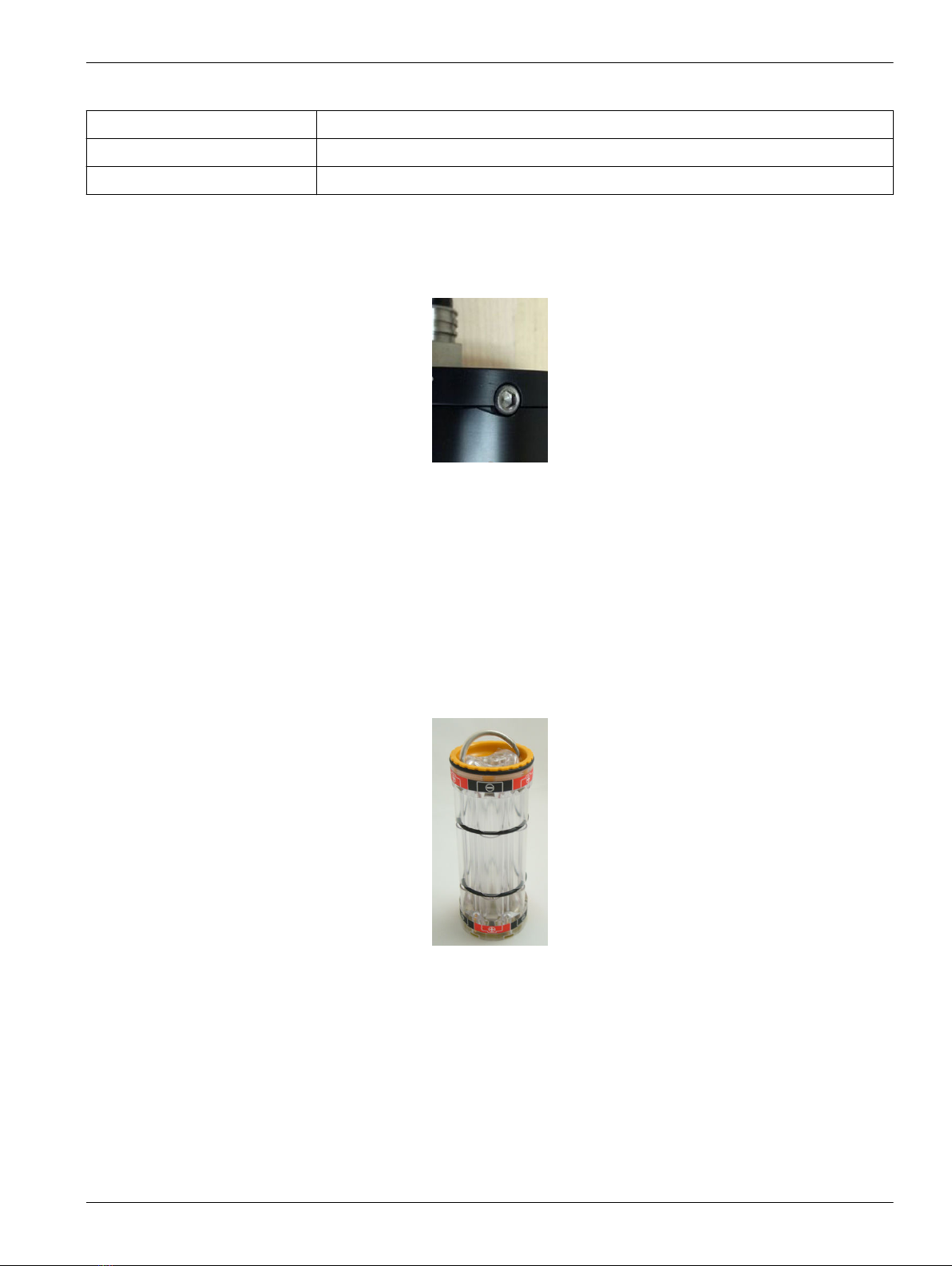
Table 5 Recommended lithium battery brands
SAFT LS-14500 (included) 3.6 V, 2.6 Ah
Tadiran TL-4903 3.6 V, 2.4 Ah
Electrochem BCX85 series 3.9 V, 2.0 Ah
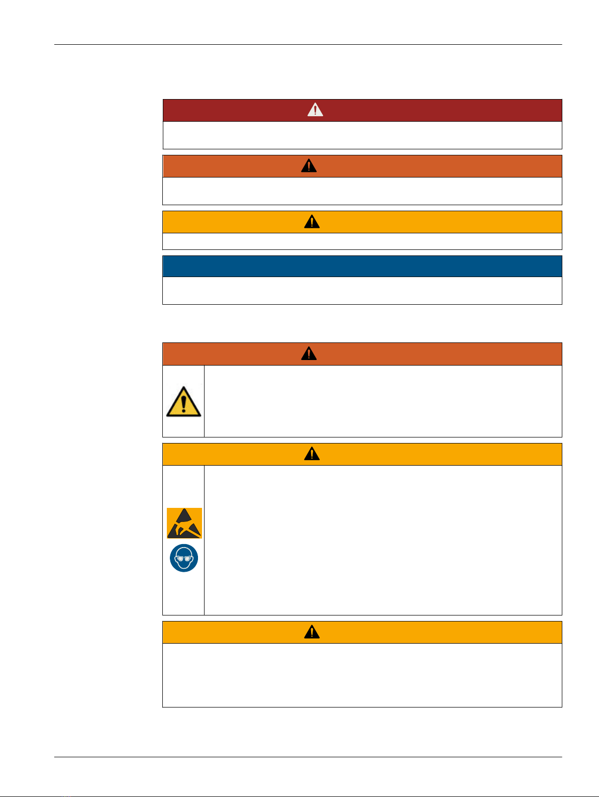
1. Make sure that the end flange and pressure housing are dry.
2. Use a 9/64" hex key to remove the two screws on the sides of the pressure housing.
3. Install these two screws into the sides of the end flange to start to loosen the end
flange.
4. If necessary, hold the bulkhead connector with a crescent wrench to make it easier to
turn the end flange.
5. Turn the end flange counter-clockwise to loosen it from the pressure housing.
6. Pull gently to disconnect the battery wires in the end flange from the battery pack.
7. Use a lint-free tissue to remove any water from the O-ring surfaces inside the
pressure housing and end flange.
8. Use a 7/64" hex key to loosen the captured screw in the battery cover plate.
9. Remove the battery pack from the pressure housing.
10. Turn the yellow cover plate counterclockwise to remove it from the battery pack body.
11. Move each of the two O-rings on the outside of the battery holder from the grooves.
It makes it easier to remove or insert batteries.
12. Examine the O-rings and surfaces for dirt, cuts, or other damage.
Clean or replace as necessary.
13. If necessary, remove the size AA batteries in the pack.
14. Insert new batteries.
Make sure to alternate the positive (+) and the negative (-) ends on the size AA
batteries to agree with the labels on the pack as they are installed.
15. Move the O-rings back into the grooves.
16. Align the pin on the yellow battery cover with the post hole in the battery pack
assembly.
Set up sensor and verify operation
17
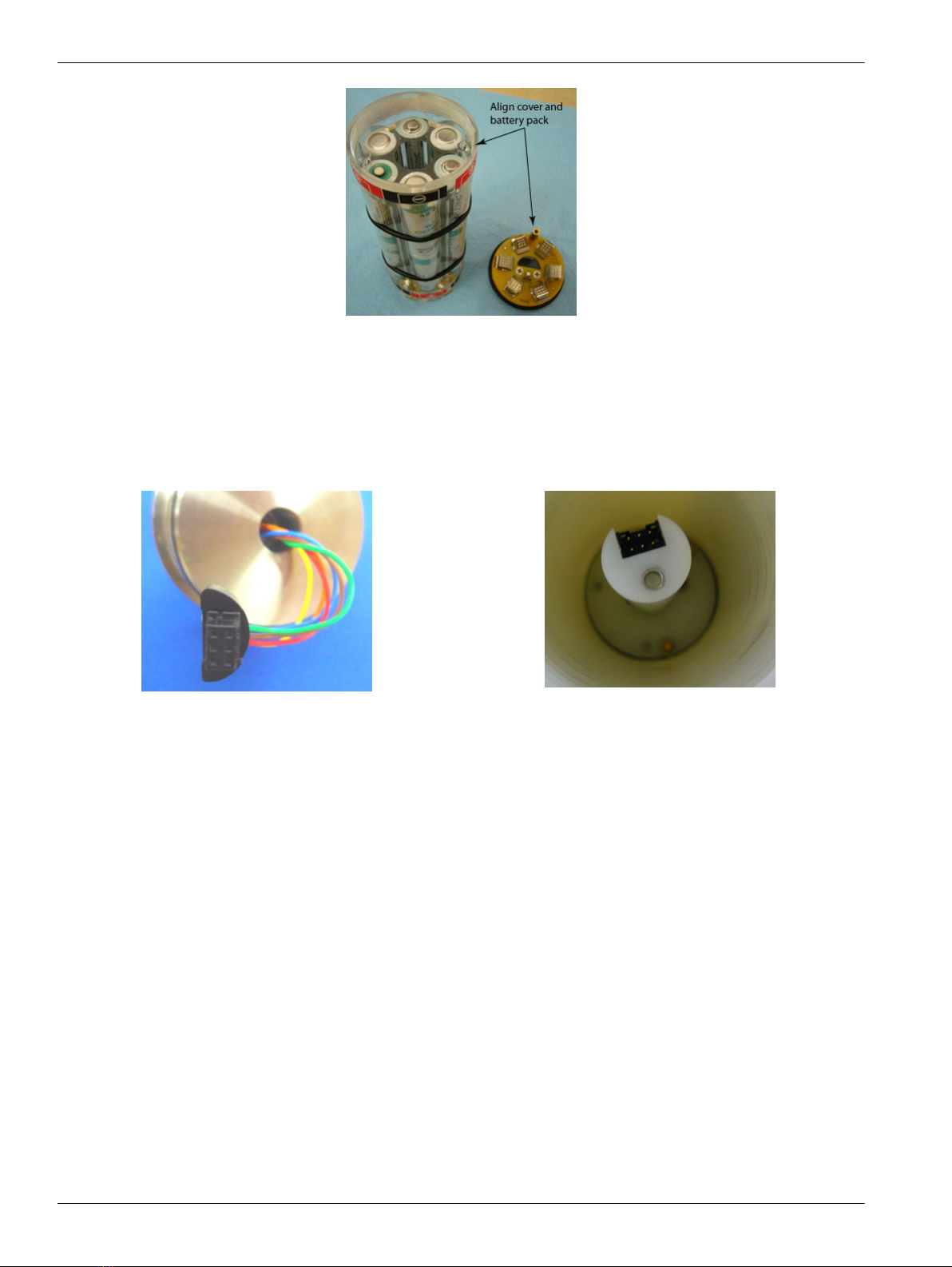
17. Align the "D"-shaped part of the battery pack with the pins on the shaft.
18. Slowly move the assembly onto the housing. Push gently to connect the battery
assembly with the circuit board in the pressure housing.
19. Use a 7/64" hex key to tighten the captured screw on the yellow battery cover onto
the shaft in the pressure housing.
20. Attach the Molex connector on the end flange to the connector in the pressure
housing.
21. Examine the O-rings on the end flange. They must be pristine, with no lint or
scratches or chips.
• Apply a small quantity of Parker Super O Lube® to any new O-rings.
22. Align the end flange holes with the holes in the pressure housing.
23. Carefully push the end flange into the pressure housing.
It may help to rotate the end flange so that the wires do not bend too much.
24. If necessary, use a 9/64" hex key to remove the two screws from the end flange.
25. Use a 9/64" hex key to install the two screws into the pressure housing of the sensor
again.
5.3 Install software and test sensor
Make sure that the sensor is connected to a power supply and PC through the serial
connector on the supplied cable. Most PCs no longer have serial ports, and a serial-to-
USB adapter is necessary. Make sure that the USB driver software is installed on the PC
so that there is communication between the sensor and the PC.
1. Install the Seasoft V2 software from the manufacturer-supplied CD.
2. Remove the dummy plug from the sensor.
3. Connect the I/O cable to the sensor and to the PC and a power supply (9–24 VDC).
4. Supply power to the sensor.
Set up sensor and verify operation
18
Other manuals for SBE 37 MicroCAT
2
This manual suits for next models
3
Table of contents
Other Sea-Bird Scientific Accessories manuals


Popular Accessories manuals by other brands


Honeywell
Honeywell IRPI8EZS manual

HEATEC
HEATEC VEGA PULS 63.UX Setting up

Dometic
Dometic Cup Cooler Installation and operating manual

GTV
GTV CR-18 instructions

ServersCheck
ServersCheck Infrasensing EST-IRSPOT Series Guide

Hubbell
Hubbell NX Distributed Intelligence NXSMP-LMI Installation and operation instructions


