Page 3 1558-1559
English/ HC-548
© Copyright 1999, Sea Gull Lighting
Pro ucts, Inc.
Note:
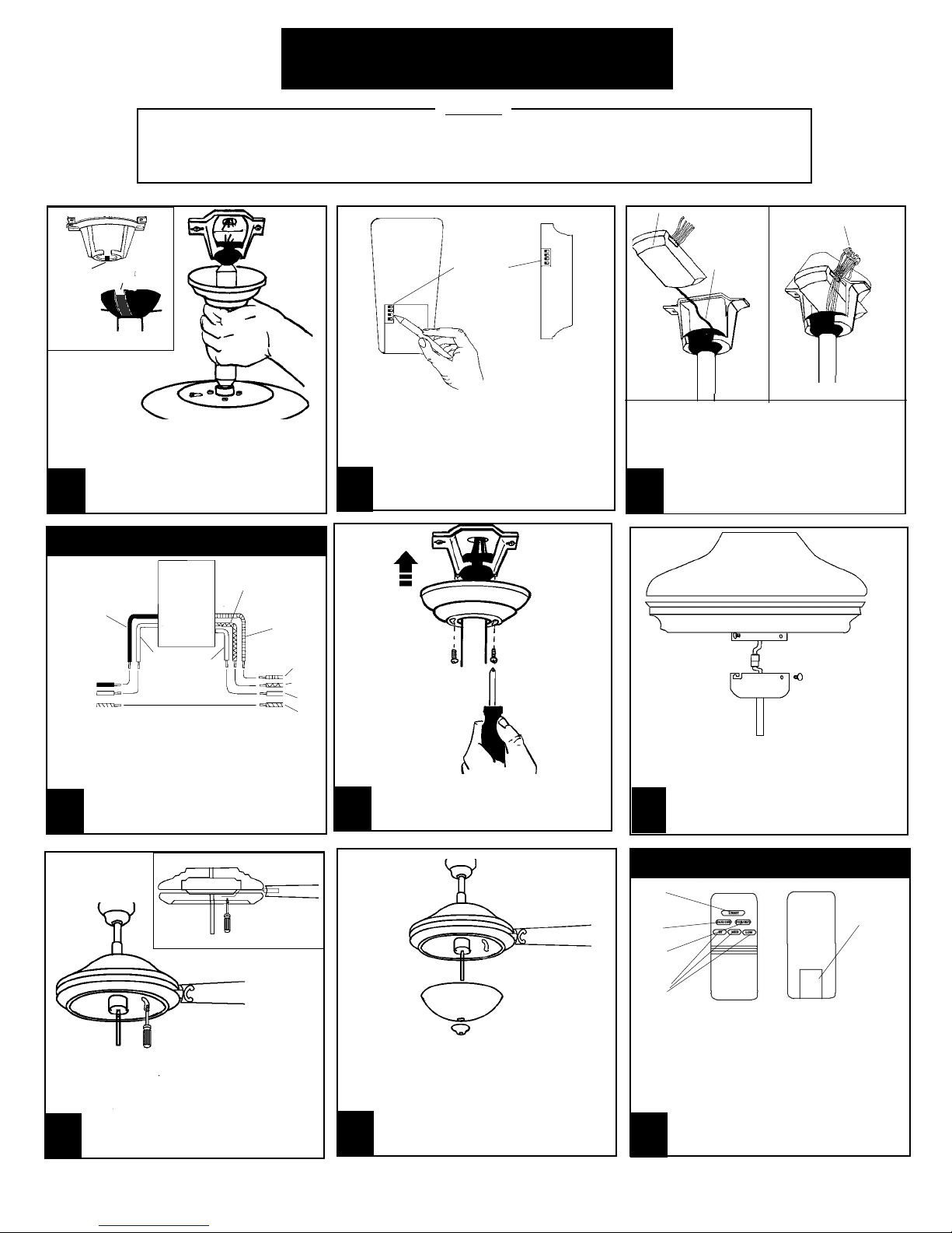
INSTALLATION
After installation, please refer to operation, maintenance an troubleshooting sections
in this manual.
1
15
7
Ri ge Ball
Notch
Remote Receiver
Antenna
Wire Nuts
FIG.A FIG.B
13
Remote Receiver
DIP Switch
Remote
Transmitter
Attach bla e assembly to motor by
inserting bracket into gap between top
an bottom housing. Use opening on in
the light fitter to insert screw river,
securing bla e assembly to 3or with
screws provi e . Tighten securely.
10
WIRING DIAGRAM
REMOTE RECEIVER
BLUE TO
LIGHT
BLACK TO HOUSE
WHITE
TO FAN
WHITE TO
HOIUSE
WHITE (COMMON)
PLAIN (GROUND)
BLACK (HOT)
WHITE
(COMMON)
BLUE (HOT)
LIGHT
BLACK (HOT)
FAN
GREEN
(GROUND)
HOUSE FAN
Make connections as shown above. Make
sure all expose con uctors are in the
wire nuts. After all connections are ma e
push wire nuts into junction box with
wire nuts pointing upwar . Note:
Refer to Point 3 in Safety Tips
Section.
First connect plug from fan to light
kit then install switch housing to
switch housing plate. Using three
screws provi e , tighten.
12
9
Carefully insert remote receiver into the
Mounting Bracket. Make sure the Antenna is
not pinche by running it through the Mount-
ing Bracket first (FIG.A). Receiver shoul be
locate as picture above(FIG.B). Make wiring
connections as per step 12. Make sure
that all wire nut connections are tight
with no expose con uctors. Point
connectors upwar an push into the
junction box.
8
Before installing the remote receiver. Make sure
the DIP switches in the Transmitter an receiver
are set the same. Use instrument with a sharp
point to move the switches into the proper
positions. The Remote will not operate if this
proce ure is not one. If interference from
outsi e transmitters or other remote
evices is incountere , change the ip
switch settings on both transmitter an
receiver.
Carefully lift fan assembly onto
mounting bracket. Rotate fan so that
the notch on the ball engages the
ri ge in the mounting bracket. This
will allow han s-free wiring.
REMOTE OPERATION
Install 9v battery by removing battery cover on back of
transmitter an connecting to terminals an re-install
cover.
FAN SPEED Depress "low" for low spee , "me " for
me ium or "hi" for high. To turn fan off press "fan/off"
LIGHT DIMMER To turn light on, press light immer
once quickly. To turn off press once quickly while the
light is on. To im light hol own button "light
immer". The light will cycle from bright to im to
bright until button is release . Light will
maintain last setting if turne off.
FORWARD REVERSE Press Forwar / Reverse
button. Fan will stop an bla es will reverse
irections.
Light
control
button
Fan
spee
controls
Battery
compart-
ment
15
Fowar /
Reverse
button
Install 3 40 Watt can elabra base light bulbs
to lamphol er by gently tightening into place.
Per illustration above. CAUTION: Do not touch
bulb with bare han s!
Attach glass sha e an cage to fan bo y by
aligning threa e pipe with hole in the
center of the glass sha e an cage. Lift
both into position. Install Finial cap.
Install finial nut an tighten to secure
glass. DO NOT OVERTIGHTEN.
Fan on
/off
RED TO FAN
MOTOR
11
Raise the canopy up an align the two
holes in the canopy with the two holes
in the hanger bracket. Secure with
two 5/32 x 1/2" screws provi e .