SEA USA UNIGATE INVERTER 1I User manual


2
11
INDEX
1 - CONNECTIONS ON THE «UNILOGIC» BASIC MODULE
2 - CONNECTIONS ON CN1
START, STOP , , , 24V
, , 10K
, «» , « » ,
13
3 - CONNECTIONS ON CN2
, , 24V «»
15
4 - CONNECTIONS ON CN3
; « »
«1» «2», , «»
16
17
18
5 - SPECIAL CONNECTIONS ON CN2 and CN3
« » , « 4»
19
6 - CONNECTIONS ON CLS - PLUG-IN LIMIT SWITCH
20
7 - CONNECTIONS ON CR1 and CR2 ( )
: ,
,
20
21
8 - CONNECTIONS ON P/S - PRIMARY/SECONDARY OPERATION ( / )
/
22
9 - CONNECTIONS ON EXP - EXTERNAL MODULES
«485» , «2» , «»
23
10 - MOTORS WIRINGS
«» , - , -
24
25
«2» , «24» , «»
11 - POWER SUPPLY
«», «2», «24», «»
26
PRELIMINARY INFORMATION AND PRODUCT DETAILS
8
14
SAFETY INFORMATION AND «UL» STANDARDS REQUIREMENTS
4
12

3
INDEX
18 - WORKING TIMES LEARNING - PROGRAMMING OF THE CONTROL UNIT
, ,
( ),
19 - OPERATING LOGICS
-, , , -- 1 2, , 2
20 - PASSWORD - PROTECTION OF THE CONTROL UNIT BY PASSWORD
21 - RECEIVERS AND TRANSMITTERS - PROGRAMMING OF THE TX
« », « », «», « »
22 - ALARMS FAULTS WARNINGS - VIA DISPLAY OR FLASHING LIGHT
,
,
23 - TROUBLESHOOTING
MENU TABLE
16 - BASIC MENU
17 - INPUTS STATUS MANAGEMENT
N.C. N.O.
15 - DISPLAY OPERATION AND PROGRAMMING MENU
, ,
13 - RECEIVERS CONNECTION ON CNR FIX
-
14 - ADDITIONAL FUNCTIONS OF THE CONTROL UNIT
/
«S » , E.F.O.
12 - CONNECTIONS ON CNB - EMERGENCY BATTERIES CONNECTIONS
UPS «» «2» , «24» «»
34
36
35
37
37
38
39
40
41
42
44
32
33
31
28
28
29
30
27

4
IMPORTANT SAFETY INFORMATION
Clean and grease parts in movement (wheels, counter-connecting rod, release, etc.)
Check for corroded parts and replace if necessary
Check if the screws and all mounting hardwares are properly tighten
Check the conditions of wear and tear of the devices in movement
Check the correct drain of the rainwater
Check the integrity of the connection cables
Inspect the track for any signs of cracking or separation
Ensure that the gate moves freely
YEARLY
YEARLY
YEARLY
YEARLY
YEARLY
YEARLY
YEARLY
YEARLY
Check and confirm the proper operation of all safety devices (photocells, edge sensors etc)
Check and confirm the operation of all installed accessories
Check and confirm the operation of the manual release
Check the battery conditions and be sure that connections are free of corrosion
Verify the functionally of the battery backup, or power failure option
GENERAL SAFETY PRECAUTIONS
The following precautions are an integral and essential part of the product and must be supplied to the user;
Read them carefully as they contain important indications for the safe installation, use and maintenance.
1. These instruction must be kept and forwarded to all possible future users of the system.
2. This product must be used only for that which it has been expressly designed.
3. Any other use is to be considered improper and therefore dangerous.
4. The manufacturer cannot be held responsible for possible damage caused by improper or unreasonable use.
5. Avoid operating in the proximity of the hinges or moving mechanical parts.
6. Do not enter the path of the moving gate while in motion.
7. Do not obstruct the motion of the gate as this may cause a situation of danger.
8. Do not allow children to play or stay within the path of the moving gate.
9. Keep remote control or any other control devices out of the reach of children, in order to avoid possible involuntary
activation of the gate operator.
10. In case of break down or malfunctioning of the product, disconnect from the main power source. Do not attempt to
repair or intervene directly, contact only qualified personnel for repair.
11. Failure to comply with the above may create a situation of danger.
12. All cleaning, maintenance or repair work must be carried out by qualified personnel.
13. In order to guarantee that the system works efficiently and correctly it is important to have the manufacturer's
instructions on maintenance of the gate and operator carried out by qualified personnel.
14. In particular, regular checks are recommended in order to verify that the safety devices are operating correctly.
All installation, maintenance and repair work must be documented and made available to the user.
IMPORTANT SAFETY INSTRUCTIONS
WARNING – TO REDUCE THE RISK OF INJURY OR DEATH:
1. READ AND FOLLOW ALL INSTRUCTIONS.
2. Never let children operate or play with gate controls. Keep the remote control away from children.
3. Always keep people and objects away from the gate. NO ONE SHOULD CROSS THE PATH OF THE MOVING GATE.
4.Test the gate operator monthly. The gate MUST reverse on contact with a rigid object or stop when an object
activates the non-contact sensors. After adjusting the force or the limit of travel, retest the gate operator. Failure to
adjust and retest the gate operator properly can increase the risk of injury or death.
5. Use the emergency release only when the gate is not moving
6. KEEP GATES PROPERLY MAINTAINED. Read the owner’s manual. Have a qualified service person make repairs to
gate hardware.
7. The entrance is for vehicles only. PEDESTRIANS MUST USE SEPARATE ENTRANCE.
8. Every gate operator installation MUST have secondary protection devices agains entrapments, such as edge
sensors and photo beams more in particulary in places where the risk of entrapments is more likely to occur
9. SAVE THESE INSTRUCTIONS
OPERATORS PERIODIC MAINTENANCE
TURNING OFF THE POWER
BY MAIN SOURCE TURNED-OFF
TURNING ON THE POWER
!
YEARLY
YEARLY
YEARLY
YEARLY
YEARLY
ALL THE ABOVE DESCRIBED OPERATIONS MUST BE MADE EXCLUSIVELY BY AN AUTHORIZED INSTALLER

5
GENERAL SAFETY INFORMATION
An appliance shall be provided with an instruction manual.
The instruction manual shall give instructions for the installation, operation, and user maintenance of the appliance.
The installation instructions shall specify the need for a grounding-type receptacle for connection to the supply and
shall stress the importance of proper grounding.
The installation instructions shall inform the installer that permanent wiring is to be employed as required by local
codes, and instructions for conversion to permanent wiring shall be supplied.
INFORMATION SHALL BE SUPPLIED WITH A GATE OPERATOR FOR:
a. The required installation and adjustment of all devices and systems to effect the primary and secondary protection
against entrapment (where included with the operator).
b. The intended connections for all devices and systems to effect the primary and secondary protection against en-
trapment. The information shall be supplied in the instruction manual, wiring diagrams, separate instructions, or the
equivalent.
VEHICULAR GATE OPERATORS (OR SYSTEMS)
A vehicular gate operator shall be provided with the information in the instruction manual that defines the different
vehicular gate operator Class categories and give examples of each usage. The manual shall also indicate the use for
which the particular unit is intended as defined in Glossary, Section 3. The installation instructions for vehicular gate
operators shall include information on the Types of gate for which the gate operator is intended.
A gate operator shall be provided with the specific instructions describing all user adjustments required for proper
operation of the gate. Detailed instructions shall be provided regarding user adjustment of any clutch or pressure relief
adjustments provided. The instructions shall also indicate the need for periodic checking and adjustment by a qualified
technician of the control mechanism for force, speed, and sensitivity.
Instructions for the installation, adjustment, and wiring of external controls and devices serving as required protection
against entrapment shall be provided with the operator when such controls are shipped with the operator.
Instructions regarding intended installation of the gate operator shall be supplied as part of the installation instructions
or as a separate document. The following instructions or the equivalent shall be supplied where applicable:
IMPORTANT INSTALLATION INSTRUCTIONS
1. Install the gate operator only when:
a. The operator is appropriate for the construction of the gate and the usage Class of the gate
b. All openings of a horizontal slide gate are guarded or screened from the bottom of the gate to a minimum of 4 feet
(1.22 m) above the ground to prevent a 2-1/4 inch (57.2 mm) diameter sphere from passing through the openings
anywhere in the gate, and in that portion of the adjacent fence that the gate covers in the open position
c. All exposed pinch points are eliminated or guarded
d. Guarding is supplied for exposed rollers
2. The operator is intended for installation only on gates used for vehicles. Pedestrians must be supplied with a
separate access opening. The partial access opening shall be designed to promote pedestrian usage. Locate the gate
such that persons will not come in contact with the vehicular gate during the entire path of travel of the vehicular gate.
3. The gate must be installed in a location so that enough clearance is supplied between the gate and adjacent
structures when opening and closing to reduce the risk of entrapment. Swinging gates shall not open into public access
areas.
4. The gate must be properly installed and work freely in both directions prior to the installation of the gate operator. Do
not over-tighten the operator clutch or pressure relief valve to compensate for a damaged gate.
5. The gate operator controls must be placed so that the user has full view of the gate area when the gate is moving and
AWAY FROM THE GATE PATH PERIMETER.
6. Controls intended for user activation must be located at least six feet (6’) away from any moving part of the gate and
where the user is prevented from reaching over, under, around or through the gate to operate the controls. Outdoor or
easily accessible controls shall have a security feature to prevent unauthorized use.
7. The Stop and/or Reset button must be located in the line-of-sight of the gate. Activation of the reset control shall not
cause the operator to start.
8. A minimum of two (2) WARNING SIGNS shall be installed, one on each side of the gate where easily visible
9. FOR GATE OPERATORS UTILIZING A NON-CONTACT SENSOR:
a. See instructions on the placement of non-contact sensors for each Type of application
b. Care shall be exercised to reduce the risk of nuisance tripping, such as when a vehicle, trips the sensor while the
gate is still moving
c. One or more non-contact sensors shall be located where the risk of entrapment or obstruction exists, such as the
perimeter reachable by a moving gate or barrier

6
10. FOR A GATE OPERATOR UTILIZING A CONTACT SENSOR:
a. One or more contact sensors shall be located where the risk of entrapment or obstruction exists, such as at the
leading edge, trailing edge, and postmounted both inside and outside of a vehicular horizontal slide gate.
b. One or more contact sensors shall be located at the bottom edge of a vehicular vertical lift gate.
c. One or more contact sensors shall be located at the pinch point of a vehicular vertical pivot gate.
d. A hardwired contact sensor shall be located and its wiring arranged so that the communication between the sensor
and the gate operator is not subjected to mechanical damage.
e. A wireless contact sensor such as one that transmits radio frequency (RF) signals to the gate operator for
entrapment protection functions shall be located where the transmission of the signals are not obstructed or
impeded by building structures, natural landscaping or similar obstruction. A wireless contact sensor shall
function under the intended end-use conditions.
f. One or more contact sensors shall be located on the inside and outside leading edge of a swing gate. Additionally, if
the bottom edge of a swing gate is greater than 6 inches (152 mm) above the ground at any point in its arc of travel,
one or more contact sensors shall be located on the bottom edge.
g. One or more contact sensors shall be located at the bottom edge of a vertical barrier (arm).
INSTRUCTION REGARDING INTENDED OPERATION OF THE GATE OPERATOR SHALL BE PROVIDED AS PART OF THE USER
INSTRUCTIONS OR AS A SEPARATE DOCUMENT. THE FOLLOWING INSTRUCTIONS OR THE EQUIVALENT SHALL BE PROVIDED
NOTICE
As for misunderstandings that may arise refer to your area distributor or call our help desk. These instructions are part
of the device and must be kept in a well known place. The installer shall follow the provided instructions thoroughly.
SEA products must only be used to automate doors, gates and wings. Any initiative taken without SEA USA Inc. explicit
authorization will preserve the manufacturer from whatsoever responsibility. The installer shall provide warning notices
on not assessable further risks. SEA USA Inc. in its relentless aim to improve the products, is allowed to make
whatsoever adjustment without giving notice. This doesn’t oblige SEA to up-grade the past production. SEA USA Inc.
can not be deemed responsible for any damage or accident caused by product breaking, being damages or accidents
due to a failure to comply with the instructions herein. The guarantee will be void and the manufacturer responsibility
will be nullified if SEA USA Inc. original spare parts are not being used. The electrical installation shall be carried out by
a professional technician who will release documentation as requested by the laws in force. Packaging materials such
as plastic bags, foam polystyrene, nails etc must be kept out of children’s reach as dangers may arise.
TO RESPECT THE LAWS IN FORCE IT IS RECOMMENDED TO USE THE ENCODER WITH THE ELECTRONIC CONTROL UNIT
UL 325 ED. 6th ENTRAPMENT PROTECTION REQUIREMENTS
VEHICULAR GATE OPERATOR CLASSES
Residential Vehicular Gate Operator-Class I: A vehicular gate operator (or system) intended for use in garages or
parking areas associated with a residence of one-to-four single families
Commercial/General Access Vehicular Gate Operator-Class II: A vehicular gate operator (or system) intended for
use in a commercial location or building such as a multi-family housing unit (five or more single family units), hotel,
garages, retail store, or other buildings accessible by or servicing the general public
Industrial/Limited Access Vehicular Gate Operator–Class III: A vehicular gate operator (or system) intended for
use in an industrial location or building such as a factory or loading dock area or other locations not accessible by or
intended to service the general public
Restricted Access Vehicular Gate Operator–Class IV: A vehicular gate operator (or system) intended for use in an
industrial location or building such as a factory or loading dock area or other locations not accessible by or intended to
service the general public
THIS VEHICULAR GATE OPERATOR MUST BE INSTALLED WITH AT LEAST TWO INDEPENDENT ENTRAPMENT PROTECTION MEANS
AS SPECIFIED IN THE TABLE BELOW
HORIZONTAL SLIDE
VERTICAL LIFT - VERTICAL PIVOT
ENTRAPMENT
PROTECTION
TYPES
TYPE A
TYPE B1
TYPE B2
TYPE C
Inherent entrapment protection system
Non-contact sensors such as photoelectric sensors or equivalents
Contact sensors such as edge sensors or equivalent devices
Inherent force limiting, inherent adjustable clutch or inherent pressure relief device
TYPE D Actuating device requiring constant pressure to maintain opening or closing motion of the gate
SWING
VERTICAL BARRIER (ARM)
A , B1*, B2* or D A , B1*, B2*, C or D
GATE OPERATORS CATEGORY (Effective January, 12 2016)

7
NOTES:
1. The same type of device shall not be used for both entrapment protection means. Use of a single device to cover both
the opening and closing directions is in accordance with the requirement; however, a single device is not required to
cover both directions. Tice installer is required to install entrapment protection devices in each entrapment zone
2. FOR VERITICAL BARRIERS ONLY: Barrier gate operators (arm) that is not intended to move toward a rigid objact
closer than 16 inches (406 mm) are not required to be provided with a means of entrapment protection
* B1 and B2 means of entrapment protection MUST be MONITORED
Changes to UL 325 ED. 6th for Gate Operators
Starting on Jan. 12, 2016, new UL 325 changes take effect, bringing a series of new mandates for the gate
operator industry. Here’s a quick guide to the key modifications
1. ENTRAPMENT-PROTECTION DEVICES: Gate operators are required to have a minimum of two independent means of
entrapment protection where the risk of entrapment or obstruction exists. A manufacturer can use two inherent-type
systems, two external-type systems, or an inherent and an external system to meet the requirement. However, the
same type of device cannot be used for both means of protection.
2. MONITORING REQUIRED: An external non-contact sensor or contact sensor may be used as a means of entrapment
protection. However, the sensor must be monitored once every cycle for:
a. the correct connection to the operator
b. the correct operation of the sensor
If the device is not present, not functioning, or is shorted, then the gate operator can only be operated by constant
pressure on the control device. Portable wireless controls will not function in this case.
3. ENTRAPMENT RISK IDENTIFICATION: As in the past, it’s up to the installer to examine the installation and determine
where a risk of entrapment or obstruction exists. Manufacturers are required to provide instructions for the placement
of external devices, but they give only examples of suggested entrapment protection in their installation manuals. If the
installer identifies a risk of entrapment or obstruction, at least two independent means of entrapment protection are
required.
4.TERMINOLOGY CHANGE: The terms «primary» and «secondary» have been removed in the description of entrapment
protection devices. This was done to emphasize that all entrapment protection devices are equally important.
5. THE END OF TYPE E: Type E (audible alarm) devices can no longer be used for entrapment protection. This change
was made because the Type E device is really a warning device, not an entrapment-protection device. Also, all gate
operator classes are now required to have an audio alarm that sounds when two successive obstructions are
encountered via a contact-type system.
6. ACCESS CONTROL LOCATION FOR EMERGENCY USE: An exception has been added in the manufacturer’s instructional
requirements for the location of controls that operate the gate.
The instructional requirements state that these controls must be at least 6' away from any moving part of the gate. In the
new exception, «Emergency access controls only accessible by authorized personnel (e.g., fire, police, EMS) may be
placed at any location in the line-of-sight of the gate».
7. BARRIER-ARM OPERATOR EXCEPTION: An exception has changed for barrier-arm gate operators requiring entrapment
protection. The previous exception stated that a barrier-arm operator did not require entrapment protection if the arm
did not move toward a rigid object closer than 2". The distance has been reduced to 16" so it more closely aligns with the
industry-defined entrapment protection provisions in ASTM F2200.
8. GATE OPERATOR CLASS II AND CLASS III DEFINITIONS: The definitions for installation classes for gate operators were
modified. Class II now includes commercial locations accessible to the general public. Class III was refined to specify
industrial locations not accessible to the general public. These changes, while seemingly minor, may affect which gate
operator is suitable for a particular installation location.
8
UNIGATE ,
,
T , , «UNILOGIC» ,
, ,
a
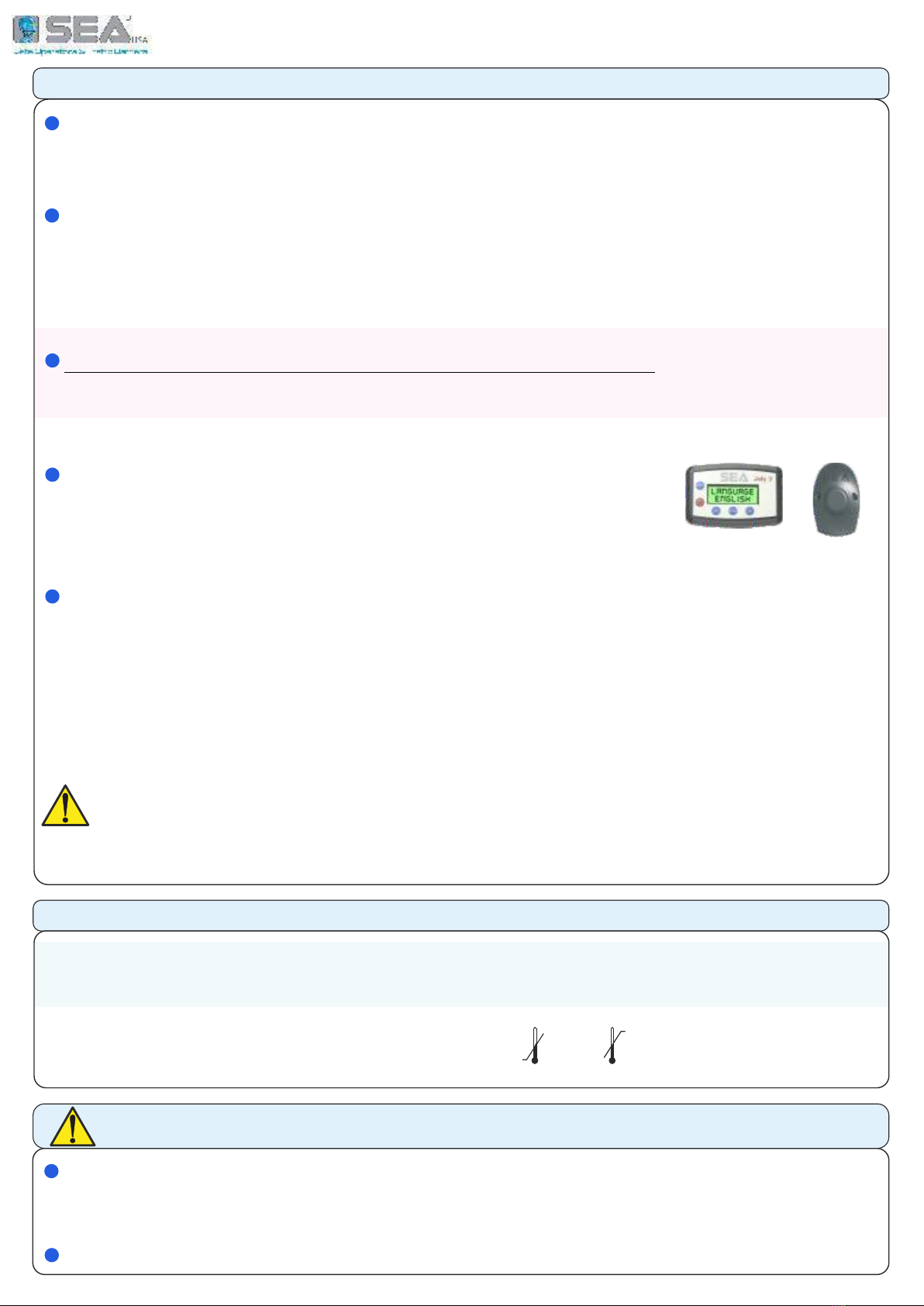
JOLLY 3 SEACLOUD
T
JOLLY 3
SEACLOUD
T UNIGATE ( 18);
!
T - UNILOGIC
I (FV) 03.12
F
; ,
24V 00.04
BR 00.28
A (, )
;
PRELIMINARY
IMPORTANT SAFETY INFORMATION - RESET BUTTON
UNIGATE « » UL STANDARDS (UL325).
A , BUZZER .
T B , « »
C « » , 5 6 ( 2.3)
TECHNICAL INFORMATION
-
230V - 50/60 H
115V - 50/60 H
30 mA
-20° C +50°C
( )
IP 55

9
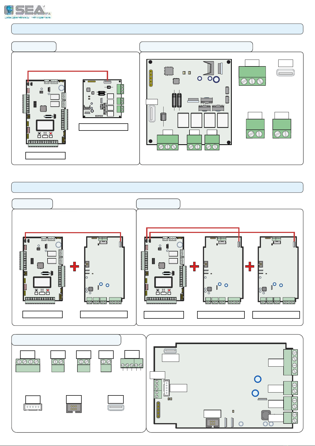
UNIGATE INVERTER 1I UNIGATE INVERTER 2I
«UNILOGIC» «FV-BIG» MODULE «UNILOGIC» «FV-BIG»
MANAGEMENT OF
1 OPERATOR WITH INVERTER
MANAGEMENT OF
2 OPERATORS WITH INVERTER
«FV-BIG»
UNIGATE INVERTER - «FV» MODULE
PE
L N
U V W
C5A DRY
POWER
MOTOR USB
5A Relay
Phase
D !
Neutral
Ground
Dry Contact
USB CONNECTOR
TO «UNILOGIC»
«UNILOGIC» «FV» MODULE
PE
L N U V W
C5A DRY
98
7
6
5
4
3
2
110 13
12
11
2221
20
19
18
17
16
15
14
23 26
25
24 27 30
29
28
UP DOWN OK
-
-
------ --
------ --
------ --
------ --
«UNILOGIC»
PE
L N U V W
C5A DRY
98
7
6
5
4
3
2
110 13
12
11
2221
20
19
18
17
16
15
14
23 26
25
24 27 30
29
28
UP DOWN OK
-
-
------ --
------ --
------ --
------ --
PE
PE
L N
L N
U V W
U V W
C5A
C5A
DRY
DRY
PE
L N U V W
C5A DRY
98
7
6
5
4
3
2
110 13
12
11
2221
20
19
18
17
16
15
14
23 26
25
24 27 30
29
28
UP DOWN OK
-
-
------ --
------ --
------ --
------ --
UNIGATE INVERTER 1I-BIG
CONNECTIONS ON «FV» MODULE
PE
L N U V W
C5A DRY
98
7
6
5
4
3
2
110 13
12
11
2221
20
19
18
17
16
15
14
23 26
25
24 27 30
29
28
UP DOWN OK
-
-
------ --
------ --
------ --
------ --
UNIGATE INVERTER 2I-BIG
PE
L N U V W
C5A DRY
MANAGEMENT OF
1 «BIG» OPERATOR WITH INVERTER
MANAGEMENT OF
2 «BIG» OPERATORS WITH INVERTER
Motor
Motor
Motor
MOTOR
POWER
USB
COMPONENTS ALSO VALID FOR «FV-BIG» MODULE
«FV» MODULE «FV» MODULE
I
«»
10
USB
-
S+
M 1
+
M 2
CN2 CN3
UNIGATE 24V
CN1
L1
L2
-
S+ M 1
+
M 2
CN2 CN3
USB
CN1
UNIGATE 24V - «24V» MODULE
CONNECTIONS ON «24V» MODULE
L1
L2
-
S+ M 1
+
M 2
«UNILOGIC»
98
7
6
5
4
3
2
110 13
12
11
2221
20
19
18
17
16
15
14
23 26
25
24 27 30
29
28
UP DOWN OK
-
-
------ --
------ --
------ --
------ --
1 or 2 24V OPERATORS MANAGEMENT
«24V» MODULE
USB
CONNECTOR
TO «UNILOGIC»
POWER
SUPPLY
CONNECTOR
MOTOR 1 and MOTOR 2
CONNECTORS
UNIGATE BR UNIGATE 2BR
«UNILOGIC» «BR» MODULE
98
7
6
5
4
3
2
110 13
12
11
2221
20
19
18
17
16
15
14
23 26
25
24 27 30
29
28
UP DOWN OK
-
-
------ --
------ --
------ --
------ --
«UNILOGIC» «BR» MODULE
98
7
6
5
4
3
2
110 13
12
11
2221
20
19
18
17
16
15
14
23 26
25
24 27 30
29
28
UP DOWN OK
-
-
--------
--------
--------
--------
«BR» MODULE
1 BRUSHLESS OPERATOR
MANAGEMENT
2 BRUSHLESS OPERATORS
MANAGEMENT
UNIGATE BR - «BR» MODULE
5 4 3 2 1
-
+
-
+
B B+
-
PE U V W
5 4 3 2 1
-
+
-
+
B B+
-
PE U V W
5 4 3 2 1
-
+
-
+
B B+
-
PE U V W
ENCODER
RAPID
CONNECTOR
EXTERNAL
MODULE
CONNECTOR
MOTOR
CONNECTOR BATTERY
CONNECTOR
USB CONNECTOR
TO «UNILOGIC»
-
+
-
+
B+ B
-
W V U PE
CN5
USB
1 2 3 4 5
CNE EXP
A
B
C
+ 5V
GND
CN1 CN2 CN3 CN4
POWER
20V / 48V
OUTPUT
24V - 2A
5 4 3 2 1
-
+
-
+
B B+
-
PE U V W
CN5
CN1
CN2
USB
CNE
EXP
CN3
CN4
CONNECTIONS ON «BR» MODULE

11
1 - CONNECTIONS ON «UNILOGIC» MODULE
Start
Stop
Common
Antenna
Common
Photocell 1
Common
Lamp
500mA max
*AUX programmable
24Vdc 1A max.
Photocell 2
Partial START
-
Safety edge 2
UP DOWN OK
BLACK WHITE RED
+
CN1
ANT COM START STPD STOP COM PH1 PH2 EDGE1 EDGE2 COM AUX FL(-)
CN2
Common
Common
Opening limit switch 1
Closing limit switch 1
Opening limit switch 2
Closing limit switch 2
EXTERNAL
MODULE
CONNECTOR
JOLLY
JOLLY 3
SEACLOUD
EXP
RF RECEIVER
CONNECTOR
PRIMARY
SECONDARY
CONNECTOR
CNR
P/S
CNP
OPEN
(Firmware update)
FIX
RF FIX RECEIVER
CONNECTOR
COMIS - max. 350 mA
Common accessories
*24V - max. 1A
CR1
LSO1 LSC1 COM LSO2 LSC2 24V+ COMIS LOCK
+
-
-
Electric lock
CN3
+PG E1/D1 COM E2/D2 GP1 GP2 COM 24V
(+) Position Gate
Data Position Gate 1
Data Encoder 1
Data Position Gate 2
Data Encoder 2
Programmable input 1
Programmable input 2
(+) Encoder
*24V max 1A
Common
CR2
RELAY 1
DRY CONTACT
RELAY 2
DRY CONTACT
CLS
LIMIT SWITCH
QUICK
CONNECTOR
M1 M2
MODULES
CONNECTORS
MOTOR 1 or 2
CNB
BATTERY
CONNECTOR
PW
UNIT
POWER SUPPLY
PROGRAMMING BUTTONS
* A 24V (24VAUX CN1 - 24VDC(+) CN2 - 24V(+) CN3) 1A
24V ,
(30 mA)
98
7
6
5
4
3
2
110 13
12
11
14 15 16 17 18 19 20 21 22 23 24 25 26 27 28 29 30
COM1 NO1 NC1
COM1 NO1 NC1
S
+
-
+
-
«» - «24» - «»
98
7
6
5
4
3
2
110 13
12
11
2221
20
19
18
17
16
15
14
23 26
25
24 27 30
29
28
UP DOWN OK
--------
--------
--------
--------
-
-
CN1
CN2
CN3
JOLLY
CLOUD
CNB
CR2
CLS
EXP FIX
FIX CNR
CNP
PW
POWER
BAT
DISPLAY
CR1
M1
MODULE 1
M2
MODULE 2 P/S
PRIMARY
SECONDARY
RL2
RL1
CN1
ANT COM START STPD STOP COM PH1 PH2 EDGE1 EDGE2 COM AUX FL(-)
LSO1 LSC1 COM LSO2 LSC2 24V+ COMIS LOCK
98
7
6
5
4
3
2
110 13
12
11
14 15 16 17 18 19 20 21 22
CN2
-
CN3
+PG E1/D1 COM E2/D2 GP1 GP2 COM 24V
23 24 25 26 27 28 29 30
N.C. CONTACTS
24V DC
AUTOMATIC RECOGNITION OF THE N.C. INPUTS NOT IN USE - NO JUMPERS REQUIRED ON THE N.C. CONTACTS
TO RESTORE THE EXCLUDED INPUTS USE THE «INPUTS MANAGEMENT» MENU (CHAP. 17) - NO NEED TO SET UP THE UNIT AGAIN
WARNING: CONNECT ALL DEVICES WHEN THE CONTROL UNIT IS SWITCHED-OFF
Safety edge 1

12
i
8
7
6
5
4
3
2
1
CN1
2 - CONNECTIONS ON CN1
«» « »
C «» 3 6
L «» :
19
I ,
C «» 5 6
C:
M: D: 97 = «»; 98 = « »
«» : C T- 12
95
T (24V) 19 CN2
24V AUX
TX1
TX2
24Vaux
CN1
RX1
RX2
Start
Stop
Common
Common
Common
Photocell 1
Photocell 2
Partial Start
Antenna
2.1 - START (N.O.)
2.2 - PARTIAL START (N.O.)
C « » 4 6
L « » :
19
P :
P :
I ,
a
a
90
97
95
PARTIAL
OPENING
PHOTOCELL
1
PHOTOTEST
91
PARTIAL
PAUSE
89
TRAFFIC LIGHT
RESERVATION
13
12
11
910
2.3 - STOP (N.C.)
2.4 - PHOTOCELL 1 AND PHOTOCELL 2 (N.C.)
a
a
+ = 24V 1A ( 12) COM = 0V ( 2 - 6 - 11)
PH1 = P 1 ( 7) PH2 = P 2 ( 8)
98
PHOTOCELL
2
M: AUX 94
A 24VAUX ( 2.12);
( , , .)
94
24V AUX
2.5 - OPTIONS 24V DC AUX - 1A - 12
C ( ) 4 « » 8 « 2»
I « », ( )
T ; ,
- .
I , 6 .
: I
TIMER ,
TIMER , «»
92
TIMER
2.6 - TIMER (N.O.) - EXTERNAL CLOCK
a
T , «BR»
,
A , «»
F « » - UL 325 - 8

13
98
710 12
11
UP OK
UP
UP
OK
OK
OK
CN1
CN1
13
12
11
10
9
-
+
10K
PHOTOCELL
C 12 ( 19 CN2) 13
G :
M: 86
P- : 85
C 1 9 11
C 2 10 11
C 7 - 11 - 12 and 8 - 11 - 12
C 12 and 13
U 24V 100 dB B
SAFETY EDGE 1
CN1
PHOTO 1
TYPE
121
PHOTO 1
10K
IF THE BUZZER DOES NOT RUN, MAKE SURE THE MENU
86-FLASHING LIGHT IS SET ON «BUZZER»
SAFETY EDGE 2
Edge 1
Edge 2
Common
Lamp
FL(-)
Photo1
Photo1
Photo2
Common
24V AUX
1A max
24V AUX
1A max
Lampeggiante
FL(-)
24V AUX
T (24V) 19 CN2
PHOTO1 10K
DOUBLE
13
12
11
10
9
2.7 - 24V FLASHING LIGHT - MAX 3W
2.8 - SAFETY EDGE (N.C.)
2.9 - 10K PHOTOCELL SINGLE OR DOUBLE
2.10 - BUZZER 24V
86
100
SAFETY
EDGE 1
SAFETY EDGE 1
85
PRE-
FLASHING
FLASHING
LIGHT
FLASHING
LIGHT
a
S : - 100-101
D : - 102-103
T
«»
T B 2
-
B 8K2 (
):
- ( )
101
(EXAMPLE)
102 103
100
NORMAL
BUZZER
UP
8K2 RES
a
a
a
97
86
PHOTOCELL
1
98
PHOTOCELL
2
B 10K ,
, -
P STOP ; ,
5
T B ;
, «»
i
T
; 22
1 /
2 /
S
U 10K ;
«» «»
(EXAMPLE)
OK
OK
7 8
EXAMPLE OF
LAMP AND
SAFETY EDGE
CONNECTION
SAFETY
EDGE 2
EDGE 1
DIRECTION
EDGE 2
DIRECTION
UP TO 4 10K PHOTOCELLS
EXAMPLE
OF 10K
PHOTOCELLS
CONNECTION
EXAMPLE OF 10K PHOTOCELL
AND BUZZER CONNECTION
Common
a

14
14 15 16 17 18 19 20 21 22
98
7
6
5
4
3
2
110 13
12
11
98
7
6
5
4
3
2
110 13
12
11
LATCH CLOSING
CLOSES AND KEEPS CLOSED
LATCH OPENING
OPENS AND KEEPS OPEN
2.12 - LATCH OPENING OR LATCH CLOSING BUTTON
NO COMMAND ACCEPTED NO COMMAND ACCEPTED
2.11 - SAFETY LOOP
U
«ULTRA LOOP PLUG»
(23105142)
LOOP 1 LOOP 2 LOOP 3
24V COM
-
+
SHADOW LOOP
REVERSE LOOP
FREE EXIT LOOP
CN2
LOOP 1
LOOP 2
LOOP 3
CN1
CN1
LOOP 1
-
OUT 1 LOOP 2 OUT 2 LOOP 3 OUT 3
Start
Common
Photocell 1
Photocell 2
Common
Comis
Edge 1
F ( 1)
3 = S (N.O.)
6 = C
R ( 2)
S ( 3)
7 = P 1 (N.C.)
6 = C
8 = P 2 (N.C.)
6 = C
UP
SHADOW
LOOP
98
PHOTOCELL 2
C 6 9 6 10
T
:
UP
OPENING AND
CLOSING
118
LATCH
(EXAMPLE)
T L ;
S 21.4
a
T L ,
2.13 - «FIRE SWITCH» FUNCTION
OK
OK
Common
CN2
CN1
T 24V
19 (24V+) CN2,
2.14 - EXTERNAL RECEIVER
6
5
4
3
2
114 15 16 17 18 19
Start
Partial Start
Common Common 24VDC (+)
T - « »
« 2»
8
7
6
5
4
3
2
1
CN1
Partial Start
Common
T - « »
.
T « »
93
UP
ON
PARTIAL
START
93
FIRESWITCH
(EXAMPLE)
OK
EXAMPLE OF
SAFETY LOOP CONNECTION
a
a

15
18 19 20 21 22
CN2
14 15 16 17 18
18 19 20 21 22
18 19 20 21 22
CN2
CN2
CN2
3 - CONNECTION ON CN2
N.C.
N.C.
N.C.
N.C.
14
16
15
16
17
16
18
16
3.2 - 12V - 3A max ELECTRIC LOCK CONNECTIONS
24VDC (+) (19) CN2 24V
(: )
Com
Electric lock
3.3 - 24VDC (+) INPUTS
24V (+)
3.4 - «COMIS» INPUT
COMIS
24V (+)
I , 1 ; I
2 !
T , CLS
F «BIG FAST», «JOINT 4 LS» BOLLARDS, 5
3.1 - LIMIT SWITCH
C
12V - 15W
UP
UP
UP
UP
UP
OK
OK
OK
OK
OK
a
a
T
i
(
); I ,
OPENING
AND
CLOSING
OPENING
AND
CLOSING
3 SECONDS
79
77
78
ANTI
INTRUSION
LOCK
TIME
LOCK
(EXAMPLE)
(SETTING EXAMPLES)
L
L
i
T « »
76
PUSHING
STROKE
2 SECONDS
I 20- CN2 24V
( . 350 mA)
B 20
«», . S
T «»
OK
200 mA
137
138
COMIS
COMIS
THRESHOLD
T «»
. :
250 mA
T
(« » - - 22)
(EXAMPLE)
Electric lock
EXAMPLE OF LIMIT SWITCH
CONNECTIONS
OPENING LIMIT SWITCH
MOTOR 1
CLOSING LIMIT SWITCH
MOTOR 1
OPENING LIMIT SWITCH
MOTOR 2
CLOSING LIMIT SWITCH
MOTOR 2
A- :
(SETTING EXAMPLE)
a
a

16
OK
OK
OK
UP
UP OK
OK
OK
UP OK
OK
UP UP
OK OK
CN3
23 24 25 26 27 28 29 30
4 - CONNECTIONS ON CN3
4.1 - ENCODER CONNECTION
SPECIAL MENU
LANGUAGE
1
SPECIAL MENU
16
ON
ENCODER
32
E 32
ENCODER
32
47-ENCODER PAR M1
ENCODER PAR M1
47
XXX
ENCODER
32
ENCODER TOT M1
48
XXX
ENCODER PAR M1
47
4.2 - ENCODER PARAMETERS ADJUSTMENT
S : 10% ( ) - 99% ( )
I OFF ( ),
M1 OPENING
SENSITIVITY
33
XX%
M1 CLOSING
SENSITIVITY
34
XX%
T E MOTOR 1 (M1); F MOTOR 2 (M2) 49 50
ENCODER M1 ENCODER M2
BLUE/WHITE 24
RED/BROWN 30
BLACK/GREEN 25 (29)
17
OP. SPEED
C CN3;
:
OLD MODEL BROWN - WHITE - GREEN
NEW MODEL RED - BLUE - BLACK
UP
DOWN
UP
DOWN
48-ENCODER TOT M1
a
a
a
O C
F «ABC» E
«BR» , 10.4.
F RS 485 E , 9.1
BLUE/WHITE 26
RED/BROWN 30
BLACK/GREEN 25 (29)
T E MOTOR 1 (M1); F MOTOR 2 (M2) 35 36
a
CN3
23 24 25 26 27 28 29 30
UP OK UP OK OK
T :
WHITE/BLACK 24
GREEN/BLUE 23
BROWN 25 (29)
4.3 - «POSITION GATE» LINEAR POTENTIOMETER CONNECTION
POTENTIOMETER M1 POTENTIOMETER M2
SPECIAL MENU
LANGUAGE
117
SPECIAL MENU
16
ENCODER
32
POTENTIOMETER
ON
OP. SPEED
UP
DOWN
UP
DOWN
C « »
CN3 ,
OLD MODEL BROWN - GREEN - WHITE
NEW MODEL BROWN - BLUE - BLACK
R
WHITE/BLACK 26
GREEN/BLUE 23
BROWN 25 (29)
a
F 2m, 3-
(25 29)

17
UP
4.4 - «POSITION GATE» POTENTIOMETER CONFIGURATION
P : 1 ( 51) 2 ( 54)
I. PAR. M1
51
POTENTIOMETER
T « »
( 22);
( )
4.5 - «POSITION GATE» POTENTIOMETER PARAMETERS ADJUSTMENT
OK UP
I. PAR. M2
54
OK
XX
P : 1 ( 52) 2 ( 55)
;
UP
UP
OK
OK
UP OK
XX
52
I. AP. M1
55
I. AP. M2
UP
DOWN
P : 1 ( 52) 2 ( 55)
;
UP
OK UP OK
OK
XX
XX
53
I. CH. M1
56
I. CH. M2
UP
UP
DOWN
DOWN
S (M 1 M 2)
33
M1 OPENING
SENSITIVITY
34
M1 CLOSING
SENSITIVITY
35 36
OK
XX
UP
DOWN
P (M 1 M 2)
38
M1 POT. THRES.
OPENING
39
M1 POT. THRES.
CLOSING
40
M2 POT. THRES.
OPENING
41
M2 POT. THRES.
CLOSING
i
S OFF ( ): ( )
F
OK
XX
UP
DOWN
P (
(M1 - M2)
42 43 44 45
OK
XX
UP
DOWN
S
37
SLOW DOWN
SENSITIVITY
4.6 - ACCESS TO THE HIDDEN «DEBUG» MENU FOR POTENTIOMETER
03.12
VP 1
OK
XXX
see chap. 15
D «VP1» «VP2» ( 1 2)
(
VP1 VP2)
T ,
F
POTENTIOMETER
POTENTIOMETER
M2 OPENING
SENSITIVITY
M2 CLOSING
SENSITIVITY
M1 POT. THRES.
SLOWDOWN OP.
M1 POT. THRES.
SLOWDOWN CL.
M2 POT. THRES.
SLOWDOWN OP.
M2 POT. THRES.
SLOWDOWN CL.
T ,
a
a
a
a

18
CN3
CN3
23 24 25 26 27 28 29 30
23 24 25 26 27 28 29 30
4.8 - TEMPERATURE PROBE CONNECTION
SCREW THE TEMPERATURE PROBE TO REPLACE THE OIL CAP
ON GP1 (CLAMP 27) AND COM (CLAMP 29)
OR ON GP2 (CLAMP 28) AND COM (CLAMP 29)
REMOVE
THE OIL
CAP
12
4.9 - ACTIVATION AND SETTING OF THE TEMPERATURE PROBE
LOW TEMPERATURE
THRESHOLD
*
GP1
GP1
GP1 (27) = PROGRAMMABLE INPUT 1
COM
*
*
OR MENU 131 FOR GP2 INPUT
*
4.7 - «GP1» e «GP2» PROGRAMMABLE INPUTS
GP2
GP2 (28) = PROGRAMMABLE INPUT 2
4.10 - «CAGE» FUNCTION ON MENU «GP1» and «GP2»
«GP1» «GP2»
(..
) .
GP1
130
GP2
131
C CN3
C «» CN3
T ;
I ,
,
UP OK UP OK OK
A
SPECIAL MENU
LANGUAGE
117
SPECIAL MENU
16
ON
OP. SPEED
UP
DOWN
GP1
130
TERMOMETER
*
UP OK UP OK
D
SPECIAL MENU
LANGUAGE
117
16 109
XX °C
UP OK UP OK
S /
SPECIAL MENU
LANGUAGE
117
16 110
XX °C
UP
HIGH TEMPERATURE
THRESHOLD
111
F «FV» - U I
«CAGE» :
CN3
23 24 25 26 27 28 29 30
GP1
COM
GP2
*
OR MENU 131 FOR GP2 INPUT
*
OK OK
ON
UP
GP1
130
CAGE
T M1 M2 « » :
GP1 - M1 M2
GP2 - M2 M1
a
I : 130 131
SPECIAL MENU
SPECIAL MENU
T LOW
THRESHOLD
OP. SPEED
OP. SPEED
TERMOMETER
T HIGH
THRESHOLD
ON GP1 (CLAMP 27) AND COM (CLAMP 29)
ON GP2 (CLAMP 28) AND COM (CLAMP 29)

19
14 15 16 17 18
23 24 25 26 27 28 29 30
5 - SPECIAL CONNECTIONS ON CN2 and CN3
5.1 - «BIG FAST» OPERATOR LIMIT SWITCH CONNECTION
5.2 - «JOINT 4 LS» or BOLLARDS LIMIT SWITCH CONNECTION
Common
Common
MOTOR 1
LIMIT SWITCH
MOTOR 2
LIMIT SWITCH
1
1
1
23
4
56789
10
2
2
3
3
4
4
5
5
MOTOR 1 OPENING LIMIT SWITCH
MOTOR 1 OPENING LIMIT SWITCH
MOTOR 1 CLOSING LIMIT SWITCH
MOTOR 1 CLOSING LIMIT SWITCH
MOTOR 1 COMMON
MOTOR 1 COMMON
MOTOR 1 OPENING SLOWDOWN LIMIT SWITCH
MOTOR 1 OPENING SLOWDOWN LIMIT SWITCH
MOTOR 1 CLOSING SLOWDOWN LIMIT SWITCH
MOTOR 1 CLOSING SLOWDOWN LIMIT SWITCH
6
6
7
7
8
8
9
9
10
10
MOTOR 2 OPENING LIMIT SWITCH
MOTOR 2 OPENING LIMIT SWITCH
MOTOR 2 CLOSING LIMIT SWITCH
MOTOR 2 CLOSING LIMIT SWITCH
MOTOR 2 COMMON
MOTOR 2 COMMON
MOTOR 2 OPENING SLOWDOWN LIMIT SWITCH
MOTOR 2 OPENING SLOWDOWN LIMIT SWITCH
MOTOR 2 CLOSING SLOWDOWN LIMIT SWITCH
MOTOR 2 CLOSING SLOWDOWN LIMIT SWITCH
14 15 16
CN2 CN3
Common
1 «JOINT 4 LS» OPERATOR OR 1 BOLLARD 2 «JOINT 4 LS» OPERATORS OR 2 BOLLARDS
123
4
5
I «UNIGATE 4PM», 3 4
1 2;
E: M1 M3
F :
**
*
*
CN2 CN3
I 1 «BIG FAST» OPERTOR,
3
T MOTOR 2
«SLOWDOWN LIMIT SWITCH»
a
UP OK
LANGUAGE
1
SLOWDOWN
LIMIT SWITCH
12
OK
ON
I 2 «BIG FAST» OPERTORS,
Opening limit switch 1
Closing limit switch 1
Opening limit switch 2
Closing limit switch 2
Data Position Gate 1
Data Encoder 1
Programmable input 1
Programmable input 2
Data Position Gate 2
Data Encoder 2
14 15 16 17 18
23 24 25 26 27 28 29 30
Common
Common
MOTOR 1
LIMIT SWITCH
MOTOR 1
LIMIT SWITCH
MOTOR 2
LIMIT SWITCH
123
4
56789
10
CN2 CN3
Opening limit switch 1
Opening limit switch 1
Closing limit switch 1
Closing limit switch 1
Opening limit switch 2
Closing limit switch 2
Data Position Gate 1
Data Encoder 1
Data Position Gate 1
Data Encoder 1
Programmable input 1
Programmable input 2
Data Position Gate 2
Data Encoder 2
Data Position Gate 2
Data Encoder 2
i

20
UP
OK OK
UP
OK OK
CR1
CR1
COM1 NO1 NC1
COM1 NO1 NC1
CR2 T (, );
132 133
7.1 - RELAY 1 and RELAY 2 MANAGEMENT
RELAY 2
133
START
3 S
7 - CONNECTIONS ON CR1 and CR2
RELAY 1
DRY CONTACT
RELAY 2
DRY CONTACT
Max. 50W 230V Max. 100W 115V
7.2 - COURTESY LIGHT CONNECTION VIA RELAY
LINE
NEUTRAL
COURTESY
LIGHT COPY
COURTESY
LIGHT COPY
COURTESY
LIGHT
NEUTRAL
SET BEFORE !
7.3 - LOCK CONNECTION VIA RELAY
POWER SUPPLY
230V/115V/24V/12V (*)
POWER SUPPLY
230V/115V/24V/12V (*)
RELAY 1
132
88
2 SECONDS
PUSHING
STROKE
76
1 SECOND
1
2
3
VERTICAL
LOCK
O «»
CR1
COM1 NO1 NC1 COM1 NO1 NC1
(EXAMPLE)
(EXAMPLE)
a
RELAY 1
RELAY 1
132
132
T 0 240
M:
88
6 - CONNECTION ON CLS
6.1 - LIMIT SWITCH CONNECTION ON THE «CLS» QUICK CONNECTOR
CLS
EXAMPLE OF OPERATOR
WITH A PRE-WIRED LIMIT SWITCH
C -
SEA
T ,
UP
UP
UP
T -
T 24V R
*
OK
OK
OK
OK
OK
OK
LINE
NEUTRAL
NEUTRAL
COURTESY
LIGHT
This manual suits for next models
5
Other SEA USA Gate Opener manuals


