FAAC 400 User manual

400
Hydraulic Swing Gate Operator
UL325 Compliant
FAAC International Inc.
Headquarter & East Coast Operations
3160 Murrell Road
Rockledge, FL 32955
Tel. 800 221 8278
www.faacusa.com
FAAC International Inc.
West Coast Operations
357 South Acacia Avenue
Fullerton, CA 92831

2
TABLE OF CONTENTS
IMPORTANT SAFETY INFORMATION 3
Important Safety Instructions 3
Important Installation Instructions 3
General Safety Precautions 4
UL325 Gate Operator Classifications 4
Installing the Warning Signs 4
1. DESCRIPTION TECHNICAL SPECIFICATIONS 5
1.1 Dimensions 5
1.2 Wiring 5
2. INSTALLATION 6
2.1. Preliminary Checks 6
2.2. Installation Dimensions 6
2.3 General Rules 6
2.4. Installing the Operator 6
2.5. By-Pass Valves adjustment 8
3. FINAL OPERATIONS 8
4. SYSTEM TEST 9
5. MANUAL OPERATION 9
5.1 Restoring Normal Operating Mode 9
6. OUTWARD OPENING 9
7. POSITIVE STOP ACCESSORY 10
8. MAINTENANCE AND REPAIRS 11
8.1 Oil Level Check 11
9. SPARE PARTS 12
400 CBAC 12
Cylinder 13
Locking Cap 14
Rear Flange 15
455D CONTROL BOARD
1. General Description A2
2. Technical Specification A2
3. Features A2
4. Layout and Components A2
5. Electric Connections A3
6. Connection of Safety Devices A4
7. Operating Logics A6
8. Programming A6
9. Start-up A8
10. Learning Operating Times A9
11. Final Tests A9
12. Operating Modes Detailed Description A10
13. Prewired Enclosure A12
Limited Warranty A16

3
1. Install the gate operator only when the following condi-
tions have been met:
• The operator is appropriate for the type and usage
class of the gate.
• All openings of a horizontal slide gate have been
guarded or screened from the bottom of the gate to
a minimum of 4 feet (1.25 m) above the ground to
prevent a 2.25 inch (55 mm) diameter sphere from
passing through openings anywhere in the gate or
through that portion of the adjacent fence that the
gate covers when in the open position.
• All exposed pinch points are eliminated or guarded.
• Guarding is supplied for exposed rollers.
2. The operator is intended for installation on gates used by
vehicles only. Pedestrians must be provided with a sepa-
rate access opening.
3. To reduce the risk of entrapment when opening and
closing, the gate must be installed in a location that
allows adequate clearance between the gate and
adjacent structures. Swinging gates shall not open
outward into public access areas.
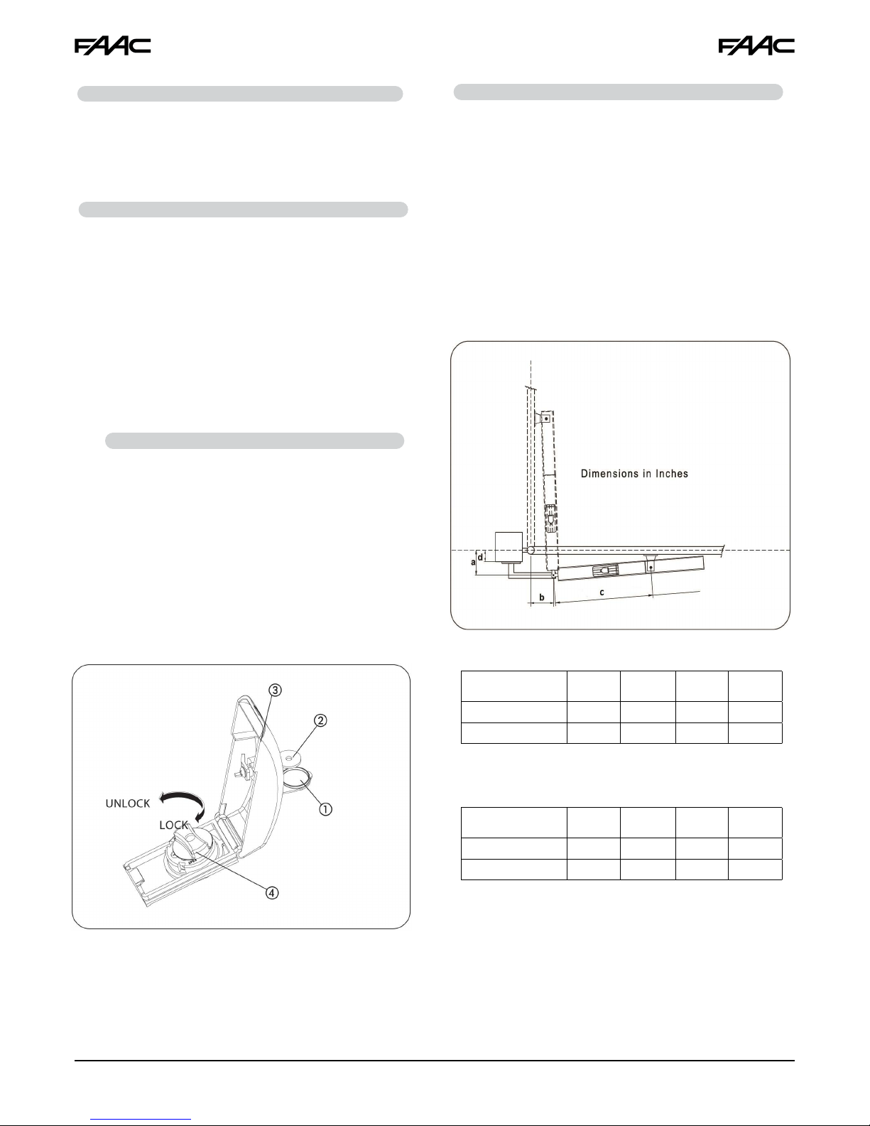
4. Before installing the gate operator, ensure that the gate
has been properly installed and that it swings freely in
both directions. Do not over-tighten the operator clutch
or pressure relief valve to compensate for a damaged
gate.
5. User controls must be installed at least 6 feet (1.83 m)
away from any moving part of the gate and located
where the user is prevented from reaching over, under,
around or through the gate to operate the controls.
Controls located outdoors or those that are easily acces-
sible shall have security features to prevent unauthorized
use.
6. The Stop and/or Reset buttons must be located within
line-of-sight of the gate. Activation of the reset control
shall not cause the operator to start.
Important Installation Instructions
• WARNING: TO REDUCE THE RISK OF SEVERE INJURY OR
DEATH:
• READ AND FOLLOW ALL INSTRUCTIONS.
• Never let children operate or play with the gate con-
trols. Keep remote controls away from children.
• Always keep people and objects away from the gate.
NO ONE SHOULD CROSS THE PATH OF A MOVING GATE.
• Test the gate operator monthly. The gate MUST reverse
on contact with a rigid object or when an object
activates a non-contact sensor. If necessary, adjust
the force or the limit of travel and then retest the gate
operator. Failure to properly adjust and retest the gate
operator can increase the risk of injury or death.
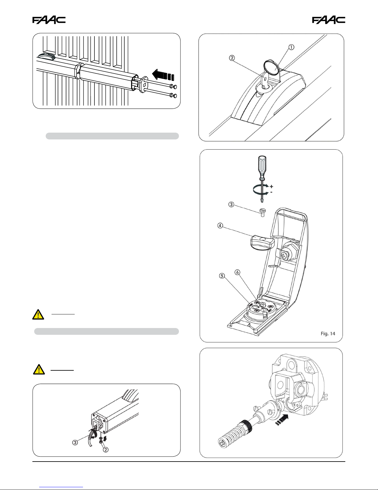
• Use the manual release mechanism only when the
gate is not moving.
• KEEP GATE PROPERLY MAINTAINED. Have a qualified
service person make repairs to gate hardware.
• The entrance is for vehicles only. Pedestrians must use
a separate entrance.
SAVE THESE INSTRUCTIONS.
IMPORTANT SAFETY INFORMATION
Important Safety Instructions
Gate Construction
Vehicular gates should be constructed and installed in
accordance with ASTM F2200: Standard Specification for
Automated Vehicular Gate Construction.
For more information, contact ASTM at: www.astm.org
Installation
• If you have any questions or concerns regarding the
safety of the gate operating system, do not install the
operator and consult the manufacturer.
• The condition of the gate structure itself directly affects
the reliability and safety of the gate operator.
• Only qualified personnel should install this equipment.
Failure to meet this requirement could cause severe
injury and/or death, for which the manufacturer cannot
be held responsible.
• The installer must provide a main power switch that
meets all applicable safety regulations.
• It is extremely unsafe to compensate for a damaged
gate by increasing hydraulic pressure.
General Safety Precautions
7. All warning signs and placards must be installed and easily
seen within visible proximity of the gate. A minimum of one
warning sign shall be installed on each side of the gate.
8. For gate operators that utilize a non-contact sensor (photo
beam or the like):
• See instructions on the placement of non-contact
sensors for each type of application.
• Exercise care to reduce the risk of nuisance tripping,
such as when a vehicle trips the sensor while the gate is
still moving.
• Locate one or more non-contact sensors where the
risk of entrapment or obstruction exists, such as at the
reachable perimeter of a moving gate or barrier.
• Use only FAAC “Photobeam” photoelectric eyes to
comply with UL325.
9. For gate operators that utilize a contact sensor (edge
sensor or similar):
• Locate one or more contact sensors where the risk of
entrapment or obstruction exists, such as at the leading
edge, trailing edge, and post mounted both inside and
outside of a vehicular horizontal slide gate
• Locate one or more contact sensors at the bottom
edge of a vehicular vertical lift gate.
• Locate one or more contact sensors at the bottom
edge of a vertical barrier (arm).
• Locate one or more contact sensors at the pinch point
of a vehicular vertical pivot gate.
• Locate hard-wired contact sensors and wiring so that
communication between sensor and gate operator is
not subjected to mechanical damage.
• Locate wireless contact sensors, such as those that
transmit radio frequency (RF) signals, where the
transmission of signals are not obstructed or impeded
by building structures, natural landscaping or similar
hindrances. Wireless contact sensors shall function under
their intended end-use conditions.
• Use only FAAC MSE MO, CN60 or M60 edge sensors.

4
• Install devices such as reversing edges and photo
beams to provide better protection for personal property
and pedestrians. Install reversing devices that are
appropriate to the gate design and application.
• Before applying electrical power, ensure that voltage
requirements of the equipment correspond to the supply
voltage. Refer to the label on your gate operator system.
Usage
• Use this equipment only in the capacity for which it was
designed. Any use other than that stated should be
considered improper and therefore dangerous.
• The manufacturer cannot be held responsible
for damage caused by improper, erroneous or
unreasonable use.
• If a gate system component malfunctions, disconnect
the main power before attempting to repair it.
• Do not impede the movement of the gate, you may
injure yourself or damage the gate system as a result.
• This equipment may reach high thermal temperatures
during normal operation, therefore use caution when
touching the external housing of the gate operator.
• Use the manual release mechanism according to the
procedures presented in this manual.
• Before performing any cleaning or maintenance
operations, disconnect power to the equipment.
• All cleaning, maintenance or repair work must performed
by qualified personnel.
RESIDENTIAL VEHICULAR GATE OPERATOR CLASS I
A vehicular gate operator system intended for use in a single family dwelling, garage or associated parking
area.
UL325 Gate Operator Classifications
COMMERCIAL / GENERAL ACCESS VEHICULAR GATE OPERATOR CLASS II
A vehicular gate operator system intended for use in commercial locations or buildings such as multi-family
housing units (five or more single family units), hotels, parking garages, retail stores or other buildings that
service the general public.
INDUSTRIAL / LIMITED ACCESS VEHICULAR GATE OPERATOR CLASS III
A vehicular gate operator system intended for use in industrial locations or buildings such as factories, loa-
ding docks or other locations not intended to service the general public.
RESTRICTED ACCESS VEHICULAR GATE OPERATOR CLASS IV
A vehicular gate operator system intended for use in guarded industrial locations or buildings such as airport
security areas or other restricted access locations that do not service the general public, and in which
unauthorized access is prevented via supervision by security personnel.
This FAAC swing gate operator is supplied with two
warning signs to alert people that a possible hazard
exists and that appropriate actions should be taken to
avoid the hazard or to reduce exposure to it.
Permanently install one warning sign on each side
of the gate so they are fully visible to traffic and
pedestrians.
Use appropriate hardware such as metal screws (not
supplied) to permanently install each warning sign.
Installing the Warning Signs

5
15 AWG
20 AWG
15 AWG
15 AWG
20 AWG
20 AWG
15 AWG
20 AWG
3
11/32”
3
11/32”
4 3/4”
MODEL CBC CBAC SB SBS CBAC
R
CBAC
EG
SB
EG
Max Traction / Thrust
Force: (daN) 620 620 620 775 465 465 465
Effective Rod Stroke:
(inches) 10 1/4 10 1/4 10 1/4 10 1/4 10 1/4 15 15
Linear Rod Speed:
(inches/sec) 0.4 0.4 0.4 0.3 0.6 0.6 0.6
Operator Weight: (lbs) 19 19 19 19 19 22 22
Use Frequency:
(cycles/hour) 70 70 70 60 80 50 50
Pump Flow-Rate:
(liters/min) 1 1 1 0.75 1.5 1.5 1.5
Hydraulic Locking:
(1) = Closing
(2) = Opening and Closing
(1) (2) / / (2) (2) /
Max Leaf Length: (feet) 16 16 18 20 12 18 20
Min Leaf Length: (feet) 9.5 9.5 9.5 12.5 9.5 11.5 11.5
Power Supply 115 VAC ± 10% or 230 VAC +6% -10% 50/60 Hz.
Absorbed Power 220 W
Absorbed Current 1A (230V) or 2A (115V)
Electric Motor 1400 rpm - 4 poles
Thermal Protection
on Windings 248 °F (120°C)
Thrust Capacitor 25uF / 115 V or 8uF / 230 V
Ambient Operating
Temperature Range -
4°F +131°F (-20 °C +55°C)
Protection Class IP55
1 DESCRIPTION AND TECHNICAL SPECIFICATIONS
The FAAC Model 400 Swing Gate Operator consists of an
electric pump and a hydraulic piston which transmits drive
to the gate leaf.
Models with hydraulic locking do not require the installation
of electric locks, as they provide mechanical locking of the
leaf when the motor is not operating.
Models without hydraulic locking require the installation of
electric locks to ensure that the leaf is mechanically locked.
FAAC 400 Operators were designed and built to automate
swing leaf gates. Do not use for any other purpose.
Figure 3
1. Operators Mod 400
2. Photocells
3. Electronic control unit
4. Key operated push-button
5. Radio receiver
6. Warning light
7. Electric lock (if necessary)
Table 1: 400 Operator – Technical Specifications
OPERATOR TYPE
STANDARD EG
A40 1/2 in 50 1/2 in
B27 1/2 in 32 1/4 in
C10 1/4 in 15 in
Always separate low voltage wiring from AC power cables.
Use separate conduits to avoid electrical interference.
The installer is responsible for grounding the gate and opera-
tor systems, for providing the main power breaker switch, and
for making sure that the entire gate system meets all applica-
ble electrical codes.
Make sure to locate all controls that operate the gate system
at least 6 ft away from any moving parts.
Figure 2
Figure 1
400 OPERATOR
1.1 DIMENSIONS
1.2 WIRING

6
Lo
Standard = 37
3/4”
, EG = 47
1/4”
Z min = 2”
S < 0
S = 0
S > 0
y Standard = 3”
y EG= 4”
2.3 GENERAL RULES
If the dimensions indicated in table A or B cannot be
achieved, the following must be considered in order to
calculate different measurements:
• To obtain 90° opening of the leaf: a + b = c.
• To obtain over 90° opening of the leaf: a + b < c.
• Lower a and b dimensions will result in higher speeds.
• Limit the difference between a and b to within 1.5 inches.
Higher differences will considerably vary gate opening
and closing speed.
• The minimum Z dimension is 2 inches (Fig. 4);
• If the pillar dimensions or the position of the hinge
(dimension d) do not make it possible to keep dimension
aat the required size, a niche must be made in the pillar
as shown in Fig. 5.
• Dimension amust always be larger than dimension E.
For installations that open outward, refer to Section 6.
Figure 4
2 INSTALLATION
2.1 PRELIMINARY CHECKS
To ensure a correctly operating automated system, the
structure of the gate must satisfy the following requirements:
• Leaf length should not exceed “Max Leaf Length”
dimensions in Table 1.
• The gate should have a strong and rigid leaf structure.
• The gate leaves should have a smooth, uniform mo-
vement during the entire length of travel without any
irregular friction.
• Existing hinges should be in good condition.
• Travel limit mechanical stops must be provided.
• The condition of the structure directly influences the
reliability and safety of the automated system.
• The gate must swing level
2.4 INSTALLING THE OPERATOR
Attention: To avoid compromising operator functionality, use
measurements and dimensions indicated.
1.) Fasten the rear attachment to a pillar or column
support. Follow the measurements indicated in Tables
A / B. If necessary, modify the length of the supplied
attachment.
• For iron pillars, weld the rear attachment (Fig. 6,
Ref. 2) directly to the pillars.
• For masonry pillars, select one of the following
solutions:
A.) Install an appropriate wall plate and then
accurately weld the rear attachment.
OR
B.) Use screws and expansion plugs to secure the
rear attachment plate (Fig. 6, Ref. a) to the pillar.
Then weld the rear attachment to the plate as
shown in Figure 6.
Table B: Recommended Dimensions for EG Operators
(*) Rod effective stroke (**) maximum dimension
Opening Angle a b c(*) d(**) s
90° 7 7/8 6 1/4 15 5 7/8 3/4
115° 6 3/4 6 1/4 15 4 3/8 3/4
125° 5 1/8 6 3/4 15 3 1/8 3/4
Opening Angle a b c(*) d(**) s
90° 5 1/16 5 1/16 10 1/4 3 1/8 3/4
115° 4 4 3/4 10 1/4 2 3/4
125° 3 1/2 4 3/4 10 1/4 1 1/2 0
Table A: Recommended Dimensions for Standard Operators
(*) Rod effective stroke (**) maximum dimension
c = In order to prevent the rod from reaching its stop point
internally when opening and closing, the effective rod
stroke is shorter than the maximum stroke.
- in inches
- in inches
Figure 5
2.2 INSTALLATION DIMENSIONS

7
Figure 6
Figure 7
1/4 Inch
Figure 8
Figure 9
Figure 10
2.) Secure the operator to the rear attachment with the
supplied screws (Fig. 6).
3.) Screw, halfway down, the front attachment onto the
rod (Fig. 8, Ref.1). Tighten with the supplied nut.
4.) Release the operator (see Section 5).
5.) Fully extend the rod out to its stopping point, then push
it back approximately 1/4 inch (Fig. 7).
6.) Relock the operator (see Section 5.1).
7.) Fit the front bracket onto the rod (Fig. 8, Ref. 2)
8.) Close the gate leaf and, while keeping the operator
perfectly horizontal, identify and mark the location of
the front bracket on the leaf (Fig. 9).
9.) Temporarily fasten the front bracket to the leaf with two
weld spots (protect rod from welding slag).
If the gate structure does not permit the bracket
to be firmly fastened, modify the structure to
create a solid support base.
10.) Release the operator and manually check that the
gate can freely and completely open. Ensure that it
stops via the travel limit mechanical stops and that
leaf movement is good and frictionless.
11.) Temporarily release the operator from the bracket
and then permanently weld the bracket to the leaf.
Prevent welding slag from damaging the rod.
(Fig.10). If welding is not feasible, secure the front and
rear attachment plates with screws.
12.) Grease all securing pins of the attachments.
13.) Prepare the protective housing and fit it on the
operator as shown in Fig. 11. Fit the electric cable
strain relief (Fig. 12, Ref. 3).
14.) Re-lock the operator and make electrical connections
to the electronic control unit following the instructions
in the 455D section.

8
2.5 BY-PASS VALVES ADJUSTMENT
The Model 400 has an anti-crushing safety device which limits
the operator’s force when an obstacle is encountered while
the gate is moving. Follow these steps to adjust the intervention
threshold of the anti-crushing system:
• Lift the protective cap (Fig. 13, Ref.1) and insert the supplied
key (Fig. 13, Ref. 2).
• Turn the key 90°clockwise to open the cover.
• Lift the cover (Fig. 14).
• Remove the screw (Fig. 14, Ref. 3) which secures the knob
and then remove the knob (Fig. 14, Ref. 4).
• Locate the force adjustment screws (By-Pass) on the
operator (Fig. 14, Ref. 5 and 6) .
• OPEN pressure screw (green wording): gate opening
direction.
• CLOSE pressure screw (red wording): gate closing
direction.
• To reduce torque, turn screws counter-clockwise.
• To increase torque, turn screws clockwise.
• Test the bypass adjustment by physically obstructing the
gate during its travel and make corrections as appropriate
• When you have finished making adjustments, re-position the
knob (Fig. 14, Ref. 4) and tighten the screw (Fig. 14, Ref. 3).
• Close the cover and lock it by turning the key counter-
clockwise.
Figure 11 Figure 13
Figure 12
15.) Connect the power cable to the operator and fasten
the screws (Figure 14A).
3 FINAL OPERATIONS
Finish the installation procedure as follows:
• Close the cover of the release device with the key.
• Remove the vent screw (Fig.12, Ref. 2).
Figure 14
Figure 14A
WARNING: Do not overtighten the screws to
compensate for a damaged gate.
WARNING: Failure to remove the vent screw may
result in erratic operation.

9
Opening Angle a
(inches)
b
(inches)
d(**)
(inches)
c
(inches)
90° 5 1/16 5 1/16 n/a 28
115° 4 4 3/4 n/a 28
6 OUTWARD OPENING
Refer to Table C for this particular application. Select the
operator according to leaf length as detailed in Table 1.
Installation dimensions are provided in Table C.
To adjust the anti-crushing system for outward opening
gates only, perform the following steps (note that these
steps differ somewhat from instructions provided in Section
4.1):
• OPEN screw (green wording): gate closing direction.
• CLOSE screw (red wording): gate opening direction.
• To reduce torque, turn screws counter-clockwise.
• To increase torque, turn screws clockwise.
4 SYSTEM TEST
When you have finished installing the unit, run a functional
check of the automated system and all accessories con-
nected to it, especially safety devices.
(**) The dimension is not a constraint
Figure 17
Table C: Standard Operators Recommended Dimensions
5 MANUAL OPERATION
If the gate has to be moved manually due to a power
failure or a fault in the system, use the release device as
described below.
• Lift the protective plug (Fig. 16, Ref. 1) and insert the
supplied key (Fig. 16, Ref. 2).
• Turn the key 90°clockwise to open the cover.
• Lift the cover (Fig. 16, Ref.3).
• Turn the release knob counter-clockwise approximate-
ly two complete turns (Fig. 16, Ref. 4).
You can now open or close the leaf manually.
5.1 RESTORING NORMAL OPERATING MODE
To prevent an involuntary pulse from activating the
operator during manual operation, cut power to the
system before re-locking the operator.
• To re-lock the operator, turn the release knob clock-
wise until it stops (Fig. 16, Ref. 4).
• Do not force the red knob as it’s designed to strip out
before damaging the operator.
• Close the cover and turn the key 90° counter-clock-
wise (Fig. 16, Ref. 2).
• Finally, remove the key and close the protective plug
(Fig. 16, Ref. 1).
Figure 16
Opening Angle a
(inches)
b
(inches)
d(**)
(inches)
c
(inches)
90° 7 7/8 7 1/2 n/a 32 3/4
115° 5 3/4 7 n/a 32 3/4
Table D: EG Operators Recommended Dimensions

10
7 POSITIVE STOP ACCESSORY
In case the gate doesn’t have built in mechanical stops, it
is possible to install, directly on the operator, an accessory
to limit the rod’s travel in both directions.
(P/N: 490109 STANDARD, 490043 EG)
The accessory is mounted on the front flange of the
operator using the supplied bolts.
With the use of the proper square shaped swivel joint (sup-
plied):
It’s possible to limit the rod’s travel and create two solid
mechanical stop positions.
NOTE: The positive stops has 4 rods, 2 are shown for illustra-
tion purpose only.
For additional details please refer to the instructions included
with the positive stop accessory.

11
8.1 OIL LEVEL CHECK
Make sure the operator is perfectly level, powered off and
that the piston is fully retracted (gate in the open position).
• Unlock the manual release cover and hinge it open
• Remove the red knob after removing the screw (Figure 18)
• The remove the 3 T20 security screws that are below the
red knob (Figure 18)
• Grab the manual release from both ends and gently rock
it while pulling up.
• Make sure to remove the o-ring that fits between the
manual release and the body of the operator
• Set the parts on a clean towel/location
• Next remove the 3 extensions grabbing them with plyers
and pulling straight up (Figure 19)
• Now rotate the collar (silver in color) clockwise by hand
and then lift straight up (Figure 20). It’s very important to
not use tools or pry on this piece
• Now look into the body of the machine and to the left,
the fluid should be up to the center of the tie rod (top for
400 standard or center for 400 EG when the piston is fully
retracted)
• The fluid should be 5/16” to 3/8” from the top of the valve
body as shown in Figure 21
• If the unit is low pour fluid in here until it reaches the target
level. If you overfill the unit it will come out the breather
hole in the rear flange.
• USE ONLY FAAC HP OIL
• Re-assembly the parts in reverse order making sure the
o-rings and surfaces are clear of debri
8 MAINTENANCE AND REPAIRS
Periodically check for correct adjustment of the anti-crushing
safety device and the effectiveness of the release system to
allow manual operation.
Safety devices installed on the system must be checked every
6 months.
REPAIRS
For repairs, contact FAAC’s authorized repair centers.
2
1
Figure 19
Figure 20
Figure 21
Figure 18
5/16”~3/8”

12
400 CBAC
Part Part Number Description
01
2036 Galvanized Nut (8mm)
02
7220015 Rear Bracket
03
7284005 Rear Bracket Plate
04
7182075 Short Pin
05
7228015 Rear Fork
06
2037 Self-Locking Nut (8 mm)
07
70991015 Gasket (D80)
09
4185045.5 Locking Cap Kit
10
701803 Self Threading Screw (4mm)
11
7119475 Vibration Dampener
12
2365 Motor Bolt (4x50 mm)
13
2366 Lock Washer (4 mm)
14
2367 Hex Nut (4 mm)
15
77000425* 115V 1400 RPM Motor
16
7119485 Vibration Dampener
17
7161825 Operator Body 400
17a
7161835 Operator Body (EG)
18
7320065 Vent Screw Label
19
7182175 Long Pin
20
701829 T20 Torx (5 x 20mm)
21
7110015 Oil Plug
22
2275 Vent Screw (4x18 mm)
23
7094065 Gasket (copper)
29
3204425 1 Lt. Lobe Pump
Part Part Number Description
30
706152 Pump Pin (4x28mm)
31 7090010015
O-Ring
32
3060 Washer (Swivel)
33
2069 Swivel Jam Nut (10mm)
34
7073095 Swivel Joint square
35
7220355 Front Mounting Bracket
35a
7220365 Front Mounting Bracket (EG)
36
703401 Star Washer (5mm)
37
7119405 Protective Cover End Cap Plug
38
7019195 Tie-Rod (Protective Cover)
38a
7019225 Tie-Rod (Protective Cover EG)
39
4170015 Protective Cover End Cap
40
7272105 Protective Cover
40a
7272115 Protective Cover (EG)
41
3900985 Skin Pack: 400
41a
3900975 Skin Pack: 400 (EG)
42
2167.1 Seal Kit
43
714019 Qt.1 FAAC Oil: 1 qt.
43a
7140251 Qt.1 FAAC Arctic Oil: 1 qt.
44**
2707 Capacitor 8uF: 220V
45
7228015.1 Aluminum Fork Kit
NOTE:
* 220 VAC 8 uF Motor p/n 7700205
* 220 VAC 16 uF Motor p/n 77000415
** 16uF Capacitor for 220 VAC Motor p/n 2706
** 25uF Capacitor for 115 VAC Motor p/n 2705

13
Cylinder
Part Part Number Description
01
7049135 Valve Retainer
02
70900500 O-Ring (10.82 x 1.78mm)
03
4404065 Inlet Valve
04
7049005 Retainer (Brass)
05
4404085 Lock Valve (Bi-Metal)
06
4994655 Distribution flange (CBAC)
07
7230295 Tie-Rod (Cylinder)
07a
7230305 Tie-Rod (Cylinder) (EG)
08
703204 Star Washer (5 mm)
09
70903000 O-Ring (7.66 x 1.78mm)
10
4180285
Shuttle Piston
11
7366025 Cylinder
11a
7366015 Cylinder (Long/EG)
12
7091015 Piston Rod Seals
13
4350105 Piston Rod Assembly
13a
4350115 Piston Rod Assembly (EG)
Part Part Number Description
14
4994625 Front Flange
15
701829 Front Flange Bolt (M5 x 20 mm)
16
63000315 Seal Front Flange (Internal)
17
7090360025 O-Ring (Distribution flange)
18
7090815 O-Ring (Retract Tube
19
7049005 Guide Ring (Piston)
20
7361335 Retract Tube
21
7310315 By-Pass Cap Spacer (see #27)
22
7210025
By-Pass Cap Spring (see #27)
23
711021 By-Pass Cap
(see #27)
24
7090280015 O-Ring (Manual Release)
25
7043055 Spacer (Manual Release)
26
4180195 Manual Release
27
4180415
By-Pass Cap Kit
28
4404095 Inlet Valve (Bi-Directional)

14
Locking Cap
Part Part Number Description
01
2151 Knob Screw (ss) 4mm x 8mm
02
7290445 Manual Release Knob w/ screw
03
701526 Screw (ss) 4 x 10mm
04
720344 Locking Cap Base
05
729043 Lock
06
7090290015 O-Ring (Lock Cylinder)
07
7275285 Top Cover
08
7131005 Key (Viro)
09
7275275 Cover, Key
10
7090855 O-Ring Extension Receptacle
11
722795 Extension Receptacle
12
7090865 O-Ring (Base to Body)
13
718358 By-Pass Extensions
14
718359 Manual Release Extensions
15
7090845 O-Ring, Extensions
16
490327 Extensions with O-Rings
17
490326 Manual Release Kit
18
4185045 Locking Cap Complete

15
Rear Flange
Part Part Number Description
01
7171485 Rear Flange
02
417010 Wiring Harness
03
63001005 Cable With Molded Connector
04
7090895 O-Ring 21x2 mm
05
7110015 Oil Plug
06
7109135 Cable Strain Relief
07
701479 Screw 3 x 12mm
08
701466 SCREW 3 x 8 mm
09
7090905 O-Ring 14 x 1.5 mm

A2
The installer is responsible for grounding the operator
system, for providing the main power breaker switch,
and for making sure that the entire gate system meets
all applicable electrical codes.
J4 J1
J3
F1
F2
PE NL
MAIN
12 45678
COMOP
M1 COMOP
M2 CL
LAMP
910111213141516171819
OPEN
AB
STP
CL OP
FSW
---
+24V
++
-TX
FSW
20 21
W.L. LOCK
J5
J2
F
22
23
24 25
FCA1
FCC1
FCA2
FCC2
–
+
STOP
OP_A
OP_B
FSWCL
FSWOP
FCC1
FCC2
FCA1
FCA2
J6
F
F1
F2
J1
J2
J3 J4
J5
J6
DL
–
+
Input Voltage 115 V~ ± 10% or
230 V~ +6% -10%
50/60 Hz
Input Power 10 W
Motor Max. Load 800 W
Accessories Max. Load 0,5 A
Electric Lock Max. Load 15 VA
Ambient Operating Temperature Range -4°F to +131°F
Protection Fuses 5A (230V version)
10A (115V Version)
800 mA (accessory)
DL STATUS AND PROGRAMMING DISPLAY
J1 LOW VOLTAGE TERMINAL BLOCK
J2 CONNECTOR FOR RADIO RECEIVER
J3 AC POWER SUPPLY TERMINAL BLOCK
J4 MOTORS AND WARNING LAMP TERMINAL BLOCK
J5 INDICATOR-LIGHT AND ELECTRIC LOCK TERMINAL BLOCK
J6 LIMIT-SWITCH TERMINAL BLOCK
F1 MOTORS AND TRANSFORMER PRIMARY WINDING
FUSE (F 5A - 230V) (F 10A - 115V)
F2 LOW VOLTAGE AND ACCESSORIES FUSE (T 800mA)
F “F” PROGRAMMING PUSH-BUTTON
– “–” PROGRAMMING PUSH-BUTTON
+ “+” PROGRAMMING PUSH-BUTTON
3. Features
Function Logics:
Semi-automatic / Automatic / Safety Devices / “Stepped” Semi-
automatic / “Stepped” Automatic / “Stepped” Safety Devices /
Semi-automatic B / Dead-man C
Opening/Closing Time:
Programmable (from 0 to 120 s)
Pause Time:
Programmable (from 0 to 4 min.)
Closing Leaf Delay:
Programmable (from 0 to 4 min.)
Opening Leaf Delay:
2 s (can be excluded)
Thrust Force:
Adjustable on 50 levels for each motor
Terminal Board Inputs:
Open / Open Free Leaf / Stop / Limit-switch / Opening Safety Devi-
ces / Closing Safety Devices / Power Supply + Earth.
Terminal Board Outputs:
Flashing Lamp / Motors / 24 VDC Accessories Power Supply / 24 VDC
Indicator-Light / Fail Safe / 12 VAC Electric Lock Power Supply
Programmable Functions:
Logic / Pause Time / Thrust Force / Torque at Initial Thrust / Opening and
Closing Leaf Delay / Reversing Stroke / Over-Pushing Stroke / Indicator-
Light / Pre-Flashing / Electric Lock / Fail Safe / Safety Devices Logic
/ Assistance Request / Detection Time of Obstacle or Contact Point
Learning Function:
Simple or complete work time learning, with or without Limit-switches
Terminal Block J3 - Power Supply
PE: Earth Connection / Ground
N: AC V~ power supply (Neutral)
L: AC V~ power supply (Line)
Connector J2 - Rapid Connection to RP Receivers
455D
RP 418 DS
RP 433 RC
1. General Description
The 455 D control board is used to operate the FAAC High
Voltage swing gate operators. It has several operating logics
built in, programmable with the help of a display and push-
buttons. The board allows connection of various accessories
including monitored photocell for compliance with the
UL325 standard Ed: 6.
The 455 D control board should be installed in an enclosure
that is conveniently located as close as possible to the gate
operator. All electrical connections from the control board
to the operator must be made in a weatherproof junction
box.
The 5 pin J2 connector allows to plug in the FAAC RP radio
receivers
455D CONTROL BOARD
2. Technical Specifications
4. Layout and Components

A3
24 V DC
3W
12 V AC
FC C2
LIMIT-SWITCHES
230 VAC
50 Hz
or
115 VAC
60 Hz
VAC MAX.
60W
OPEN A
OPEN B
STOP
BLUE
BLUE
NO NC
Maglock
+
-
NB: Capacitors are supplied with the operator.
For connection
of the safety
devices, see the
next paragraph
Terminal Block J4 - Motors and Warning Lamp
M1: COM / OP / CL: Connection to Motor 1
Must be used for single-leaf configuration
M2: COM / OP / CL: Connection to Motor 2
Cannot be used in single-leaf configurations
LAMP: Warning lamp output ( AC V ~)
Terminal Block J1 - Accessories
OPEN A - “Total Opening” Command (N.O.):
Any pulse generator (push-button, detector, etc.) which, by
closing a contact, commands opening and/or closing of
both gate leaves. To install several full opening pulse gen-
erators, connect the N.O. contacts in parallel.
OPEN B - “Partial Opening” Command (N.O.) / Closing:
Any pulse generator (push-button, detector, etc.) which, by
closing a contact, commands opening and/or closing of
the leaf driven by motor M1. In the B and C logics, it always
commands closing of both leaves. To install several partial
opening pulse generators, connect the N.O. contacts in
parallel. See logic chart for exact operation.
STP - STOP Contact (N.C.):
Any device (e.g. a push-button) which, by opening a con-
tact, is able to stop gate movement. To install several STOP
devices, connect the N.C. contacts in series.
NB: If STOP devices are not used, connect a jumper between
the STP terminals and -.
CL FSW - Closing Safety Contact (N.C.):
The closing safety input is used to protect the leaf move-
ment area during closing. While closing, an activation of
the the safety device connected to this input will reverse the
movement of the gate leaves. This input is inactive during
the opening cycle. To be compliant with the UL325 standard
at least one monitored safety device must be connected
to this input. See the next paragraph on how to connect
a monitored device. If this input is active when the gate is
open it will prevent the leaf closing movement.
OP FSW - Opening safety devices contact (N.C.):
The opening safety input is used to protect the leaf move-
ment area during opening. While opening, an activa-
tion of the the safety device connected to this input will
reverse the movement of the gate leaves. This input is
inactive during the closing cycle. To be compliant with the
UL325 standard if this input is used to protect an entrap-
ment zone at least one monitored safety device must be
connected to it. See the next paragraph on how to con-
nect a monitored device. If this input is active when the
gate is closed it will prevent the leaf opening movement.
– - Negative for power supply to accessories
+ - 24 VDC - Positive for power supply to accessories
Important: Accessories max. load is 500 mA. To calculate
current draw, refer to the instructions for individual
accessories.
-TX FSW - Negative Power to photocell transmitters.
This terminal is used for the photocells monitoring feature.
Compliance with the UL325 standard requires connecting
the transmitter photocell negative power to this input and
activating the FAIL SAFE function (see Advanced Program-
ming). This will allow the 455 D board to check the correct
operation of the safety photecells before each opening
or closing cycle.
Terminal Block J5 - Indicator-Light and Electric Lock
W.L. - Power supply to indicator-light
Connect a 24 VDC - 3 W max. indicator-light, if neces-
sary, between this terminal and the +24V supply. To avoid
compromising correct operation of the system, do not
exceed the indicated power.
LOCK - Power supply to electric lock
If necessary, connect a 12 Vac electric strike lock be-
tween this terminal and the +24V power supply. Or con-
nect a 12 Vac relay and a Maglock following the sche-
matic above.
Terminal Block J6 - Limit-Switches
These inputs are dedicated to the connection of opening
and closing limit switches
5. Electric Connections

A4
Figure C
Entrapment protection
To comply with the UL325 standard for gate operators every
entrapment zone, as defined in ASTMF2200, must be pro-
tected by two independent entrapment protection devices.
One of the devices is inherent in the FAAC operators or the
control board design, the other can be external, like a pho-
tocell or an edge sensor.
See this picture for the photocells positioning:
Closing Safety Devices Opening Safety
Devices
Opening Safety Devices:
Are active only during the gate opening movement, and
are suitable for protecting the area between the opening
leaves and fixed obstacles (walls, etc) agains the risk of
entrapment
Closing Safety Devices:
Are active only during the gate closing movement, and are
suitable for protecting the closing area against the risk of
entrapment.
Monitored Devices:
Additionaly the UL325 standard requires that every external
entrapment protection device must be monitored for
presence and correct operation. To comply with this
requirement the photeocells must be wired as shown:
1
2
5
4
3
1
2
RX OP
TX OP
1
2
5
4
3
1
2
RX CL
TX CL
910111213141516171819
OPEN
A
B
STP
CL
OP
FSW
---
+24V
++
-TX
FSW
20 21
W.L.
LOCK
-
+
-
+
-
+
-
+
-
+
+
-TX FSW
-
+
+
-TX FSW
910111213141516171819
OPEN
A
B
STP
CL
OP
FSW
---
+24V
++
-TX
FSW
20 21
W.L.
LOCK
1
2
5
4
3
1
2
-
+
-
+
RX CL
TX CL
+
-TX FSW
-
+
Figure I
Connection of One Pair of Monitored Opening
Photocells and One Pair of Monitored Closing
Photocells
Connection of One Pair of Monitored Closing Photocells
F+
+
ADVANCED PROGRAMMING
FAIL SAFE:
If this function is activated, it enables a
function test of the photocells before any
gate movement. If the test fails (photocells
not serviceable), the gate does not start the
movement.
= Active = Disabled
Display Function Default
Once the photocells are wired the Fail Safe mode of the
455D control board must be enabled. To enable it enter
in advanced programming by pressing and holding “F”
and then press “+”, scroll to the “FS” parameter and select
“Active”.
For more details please refer to the advanced programming
pararagraph.
Only one monitored photocell can be connected to the
Closing or Opening safety inputs. More than one photocell
or other device can be connected to the safety inputs, but
they will not be monitored.
Other devices connected to the safety inputs must have
normally closed contacts and wired in series with the main
monitored sensor.
See the following example of one closing safety monitored
photocell and one non monitored one.
6. Connection of Safety devices
16” or less

A5
1
2
5
4
3
1
2
RX CL 1
TX CL1
1
2
5
4
3
1
2
RX CL 2
TX CL2
910111213141516171819
OPEN
A
B
STP
CL
OP
FSW
---
+24V
++
-TX
FSW
20 21
W.L.
LOCK
-
+
-
+
-
+
-
+
-
+
+
-TX FSW
-
+
+
MONITORED
NON MONITORED
Connection of Two Pairs of Closing Photocells, One
Monitored and One non Monitored
Opening/Closing Safety Devices:
They operate during the gate opening and closing move-
ments and are suitable to protect the opening and closing
areas against the risk of impact. Typically these photocells
work in combination with other monitored photocell pro-
tecting closing or opening entrapment zones. In that case
they can’t be monitored so they can only protect against
potential impact on vehicles.
Closing Safety Devices Opening Safety
Devices
Opening/Closing Safety Devices
1
2
5
4
3
1
2
RX CL
TX CL
1
2
5
4
3
1
2
RX OP/CL
TX OP/CL
910111213141516171819
OPEN
A
B
STP
CL
OP
FSW
---
+24V
++
-TX
FSW
20 21
W.L.
LOCK
-
+
-
+
-
+
-
+
1
2
5
4
3
1
2
RX OP
TX OP
-
+
-
+
-
+
-
+
-
+
+
+
+
-TX FS
W
-TX FS
W
MONITORED
MONITORED
NON MONITORED
Connection of One Pair of Closing Photocells
(monitored), One Pair of Opening Photocells
(monitored) and One pair of Opening/Closing
Photocells (non monitored)
16” or less

A6
= Semi-automatic
= Automatic
= “Safety” Automatic
= “Stepped” Semi-automatic
= “Stepped” Automatic
= “Safety Stepped” Automatic
= “B” Semi-automatic
= Dead-man
LEAF 1 FORCE:
Adjusts thrust of Motor 1.
= minimum force
= maximum force (hydraulic)
press F
The following table displays the sequence of functions
accessible in BASIC PROGRAMMING:
BASIC PROGRAMMING
PAUSE TIME:
This has effect only when automatic logic is selected.
Adjustable from to secs. in one-second
increments.
Subsequently, display changes to minutes and tenths
of seconds (separated by a decimal point), time
is adjusted in 10-second increments, up to
minutes max. Thus, if the unit displays , Pause
Time is 2 mins. and 50 secs.
Exit from programming and return to inputs status
monitoring.
8. Programming
To program the 455D Control Board, you have to access
“PROGRAMMING” mode. Programming is split into two parts:
BASIC and ADVANCED.
LEAF 2 FORCE:
Adjusts thrust of Motor 2.
= minimum force
= maximum force (hydraulic)
LEAF 1 CLOSING DELAY:
Delays closing start of leaf 1 with respect to
leaf 2. Adjustable from to minutes (see
Pause Time).
TIME LEARNING (see Section F.3.):
Enables the selection between “simple”
learning and “complete” (manual choice of
deceleration and stop points) learning.
+≈1 s.
Simple Learning:
> 3 s.
Complete Learning:
OPERATING LOGICS (see tab. 3/a - h):
For hydraulic operators, set force to the maximum level.
Basic Programming:
To access BASIC PROGRAMMING, press key F:
• Press and hold F, the unit will display the name of the first
function / parameter.
• When you release the key, the unit will display the param-
eter’s current value.
• Value can be modified with keys +and - .
• Press and hold Fagain, the unit will display the name of
the next function / parameter.
• When you reach the last function, press Fto exit the pro-
gram, the display resumes monitoring input status.
• IMPORTANT: Make sure to exit programming mode other-
wise the changes will not be saved.
Display Function Default
+
7. Operating Logics
This is a brief description of the main operating logics of the
system. For a complete description please refer to Table 3
• A (automatic): The gate opens on command and
automatically closes after a pause phase. A second
command while opening is ignored; a second com-
mand during the pause phase interrupts the pause
time; a second command during closing reopens the
gate. A maintained open command will hold the gate
open.
• S (security): The security mode is like A logic except
that a second command during opening immediately
closes the gate. A maintained open command will not
hold the gate open.
• E (semi-automatic): This mode requires a command to
open and a command to close. A second command
during opening stops the gate. A second command
during closing reopens the gate.
• EP (semi-automatic, step by step): This mode requires
a command to open and a command to close. A
second command during opening or closing causes
the gate to stop. A third command then reverses the
previous motion of the gate.
• B (manned, pulsed): This mode is designed for guard
station use and requires a three button switch (pulsed)
to open, close, and stop the gate.
• C (manned and constant): This mode requires con-
stant pressure switches. One to open and one to close.
No pressure on a switch stops the gate.
Other manuals for 400
4
This manual suits for next models
2
Table of contents
Other FAAC Gate Opener manuals
Popular Gate Opener manuals by other brands

GiBiDi
GiBiDi FLOOR 830 manual

Keyautomation
Keyautomation CT1RD Instructions and warnings for installation and use

HySecurity
HySecurity HYNET SFP 4/1 installation manual

ALLOMATIC
ALLOMATIC OH-200DC installation manual

Eelink
Eelink Virgo Installation and user manual

Tecnoautomazione
Tecnoautomazione T3 300 Series instruction manual