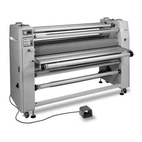
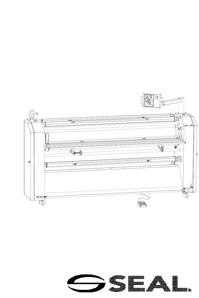
SEAL EP42 User manual

1
SEAL EP42
OWNER'S MANUAL
PLEASE READ AND SAVE INSTRUCTIONS

2
TABLE OF CONTENTS
About this manual ………………………………........……..................
Safety Precautions ……………………………………………………....
Features…………………………………………………………………...
Specifications ………………………………………….…..…………….
Names of Major Parts of Machine …………………….......................
Webbing Film …………………………………………………………….
1. Hot Film ………………………………………………………….
2. Cold Film ………………………………………………………...
Control of Roller Pressure ………………………………………………
Instructions for Control Panel …………………………………………..
1. LCD window ……………………………………………………..
2. Functions of buttons ……………………………………………
3. How to use controller …………………………………………..
Using In-Line Slitters …………………………………………………….
• Run Length Slitters ………………………………………………..
• Cross Slitter ………………………………………………………..
Process Charts ………………………………………………………...
Important Safety concerns ……………………………………………...
Maintenance ……………………………………………………………..
Trouble Shooting ………………………………………………………...
Warranty ………………………………………………………………….
3
3
4
4
5
6
6
7
8
9
9
10
11-14
15
15
16
17
18
18
19
19

3
ABOUT THIS MANUAL
Thank you for purchasing SEAL branded products. Your new SEAL EP42 has been designed
and manufactured to provide years of continuous service. To insure high quality results,
please read this instruction manual thoroughly. This manual will provide you with operating
and maintenance instructions adequate to operate and clean the machine. For additional
product support or ordering information please call Seal Graphics Americas help line at 1-800-
486-6502.
SAFETY PRECAUTIONS
The safety recommendations outlined in this section are to be read, understood and
followed before operating machine.
Keep this information for future reference. Failure to comply with any of the following
safety procedures could result in serious personal injury.
1. To prevent the possibility of electrical shock, do not immerse machine in water or permit liquid to
spill inside.
2. Do not allow articles of clothing (neckties, scarves, papers, etc.) near front or rear machine
openings as they could get caught by rollers and be pulled inside, causing personal injury.
3. Do not insert sharp objects into front or rear machine openings. Do not place anything in feed tray
openings of machine other than appropriate laminating materials or pouches.
4. Do not attempt to laminate items that exceed total recommended material thickness.
5. Do not operate machine for any other purposes than its intended use.
6. Do not operate machine if electrical plug or power cord is damaged.
7. Turn off the power when unattended or not in use. Unplug machine before moving it or when it is
not in use for an extended period of time.
8. This machine is intended for indoor use only.
9. Do not alter or extend electric plug. Plug is configured for appropriate electrical supply.
10. The socket-outlet shall be installed near the equipment and shall be easily accessible.

4
FEATURES
The design of your new SEAL EP42 Laminator features Advanced Radiant Heat Technology, offering
higher throughput speeds for most applications and the convenience of encapsulating substrates up to
1/2" without unwebbing the laminator. It's multi channel programmable controller allows you to set
individual processing criteria for optimum performance for a desired application regardless of thickness
of material or type of film. Autogrip supply shafts allow easy film alignment without tools. The standard
Foot-Pedal allows for hands-free operation at the front or rear of the machine. The Color Coordinated
Applications Chart and Nip Wheel makes selecting the proper thickness a breeze.
SPECIFICATIONS
YesSwitch-Foot
YesAss'y Stand
YesCutter-Cross
Yes - tool less AutogripFilm Alignment
YesTake-Up
2Cooling Blowers
YesCOLD and WARM Laminating
(1.3-10mil)
32 - 250micron
Film thickness
(0.5inch)
13.0mm
Max. Laminating Thickness
(41.3inch)
1050mm
Max. Laminating Width
13.1ft/min
4m/min
Max. Laminating Speed
3000wPower Consumption
AC220-240V, 50/60HzVoltage/Cycles
(308.6lbs)
140Kg
Weight
(55.1x25.6x48.0in)
1400x650x1220mm
Dimensions (w x d x h)
EP42 (Encap Pro) 42"
Laminator
Description

5
NAMES OF MAJOR PARTS OF MACHINE
2
2
9
10
11
12
13
15 1
3
4
5
14 6
1Safety Cover/Teflon Coated15
2Emergency Stop14
2Print Guide13
1Print Flattener/Teflon Coated12
4Caster11
1Foot Pedal-On/Off10
1Frame9
2Metal Roller-Heated/Teflon Coated8
2Tension control Knob-Supply7
1Nip Adjustment Lever6
1Nip Selector Wheel5
1Touch Pad Control Center4
1Take-Up Shaft Switch3
2Autogrip Supply Shaft2
1Take-Up Shaft1
EP42PART NAMENO
7
8
* not shown, rear Emergency Stop, X & Y inline film slitters

6
WEBBING FILM FOR APPLICATIONS
Encapsulation (Hot Film - Top/Bottom w/no release liner)
STEP 1-7
LEADER CARD
4
6
7
5
Hot Roller
Lower Supply
Lower Film Idler
Hot Roller
Upper Supply
Upper Film Idler
Pull Rollers
8
9
* When loading film, make sure the glossy side of (upper/lower) film lies against the
rollers. (Glossy side is film surface, whereas matte side is thermal adhesive layer).
1. Insert (upper/lower) Autogrip Shaft into film core with the tension control knob to the operators right.
2. Remove the Safety Cover and set aside (reinstall after step #7).
3. Remove feed table and print guide, set aside (reinstall after step#7).
4. Web film over the stationary film idler (upper) & Teflon Coated (heated) Film Roller (under the safety
cover), making sure to "center the film" on the roller. Leave the film draped in front of the main nip
rollers, but do not insert.
5. Move the lower film idler roller from its stationary run position to the load position by pushing up and
back, letting gravity take the roller towards the front of the machine.
6. Web the lower film up under the lower idler roller (matte side up) and in front of the lower Teflon
Coated (heated) film roller to a position just above the upper Teflon Coated Film Roller. Making
sure the films are aligned, lay the bottom film over the top film onto the upper heated Teflon Coated
film roller.
7. Set the Nip Adjustment Lever to the hard board setting (purple 1/16").
8. Reinstall table, print guide and upper teflon roller safety shield.
9. Insert a leader card (1/16" card stock, Sintra or other suitable hard stock measuring 40" wide by 12"
deep), into the main nip rollers.
10. Reset lower film idler into run position.
11. Press the run button or foot switch to process the leader card through the main nip and pull rollers
prior to processing images to be encapsulated.
12. Choose from one of the pre-programmed settings or adjust speed and temperature as desired.

7
WEBBING FILM FOR APPLICATIONS
Pressure Sensitive Applications (Laminate & Adhesive)
LEADER CARD
9
4
6
7
5
10
8
1. Insert (upper/lower) Autogrip Shaft into film core with the tension control knob to the
operators right (from the front of the machine) and align the films top to bottom by sight.
2. Remove the Safety Cover and set aside (reinstall after step #10).
3. Remove feed table and print guide, set aside (reinstall after step#10).
4. Web upper pressure sensitive film (w/release liner) under the stationary idler, then up onto
the take up shaft core, making sure the film is centered on the core. Note: using a 3" wide
strip of double sided adhesive w/release liner, apply it to the take up core, removing 1/4"
strips of release liner when needed to expose enough adhesive to tack film securely to the
core.
5. Set the Nip Adjustment Lever to the fully open Position (Orange 3/8 - 1/2").
6. Position the release point of the lower adhesive film roll so that it unwraps from the top of the
roll. Now pull the film away from the roll and extend to the mid point of the upper teflon
coated roll and then slide downward and tuck to the nip.
7. Place a 10"x40"x1/16" leader card squarely into the crease of the lower supply roll at its
separation point. Now take the lead edge of the adhesive (currently tucked to the nip) and
press up to the backside of the leader card.
8. Insert the leader card with attached adhesive into the nip. Push leader card through to the
pull rolls, leaving approximately 2" of the leader card still visable. Make sure film is taught
without wrinkles before proceeding, if required, reinsert.
9. Lower the nip selector position to the Lamination Mode (Sea Foam - Closed).
10. Using a piece of tape, place the sticky side to a corner of the release liner backed adhesive
film and pull the film & adhesive away from the release liner. Pull the entire width of film
away from the liner (now tacked to the take up core). Once the adhesive film has been pulled
cleanly away from the liner, pull the film down over the Upper Teflon Coated roller and press
against the lower adhesive just in front of the leader card, making sure to pull the film taught
and even across the roll face.
11. Reinstall table, print guide and film cover.
12. Press the run button or foot switch to process the leader card through the main nip and pull
rollers.
13. Choose from one of the pre-programmed settings for cold lamination or adjust speed and
temperature as desired.
14. Process images to be decal'ed.
8
CONTROL OF ROLLER PRESSURE
***Setting Downward Roll Pressure***
There are 4 color coded pressure settings that match the applications decal on the front of the operators
console. Match the colors on the applications decal to the nip selector wheel for desired application.
For setting the pressure, pull the lever out toward you and rotate to the desired position, then lock in
place.
The EP42 Offers the following Nip Settings
Lamination/Encapsulation position for use with films from 32 to 250microns
Mount/Laminate position for use with boards from 1/16" to 1/8“
Mount/Laminate position for use with boards from 3/16" to 1/4“
Mount/Laminate position for use with boards from 3/8" to 1/2“
The EP42 is equipped with two sets of rollers (Main & Pull) that are operated in unison by adjustment
of the Nip Lever. The pressure is factory preset for optimum results. Certain substrates (Plexiglas™ /
Sintra™) may require additional pressure… If silvering does not go away within 24 hours of lamination,
consult technical service for advice on increasing roll pressure.
Note: When not using machine it is highly recommended that you raise the nip rollers to an open
position of at least 3/16". This will prevent flat spots from occurring on the nip and pull rollers.

9
INSTRUCTIONS FOR CONTROL PANEL
The operators control panel has been designed with your convenience in mind. It's multi channel programs
allow you to customize settings for heat and speed according to your specifications. This can add greatly
to the repeatability & performance of the EP42 when used regularly with certain film combinations.
Please refer to the following instructions on how to use the EP42 Control Panel. This information will allow
you to successfully monitor the machine status, as well as set specific parameters for time and
temperature in one of 3 program channels for Cold operations and 9 program channels for Hot
applications.
Initially, when turned on, the LCD
Panel will display the last
condition it was in before being
turned off.
Is displayed when the Preset
Temperature has been reached.
A "blinking" WAIT will display
until the machine has reached
the Preset Temperature
Indicates the machine is in the
Energy Saving Mode
Upper/Lower Temperature
Indicates the Preset Temperature
Status
Speed
Indicates speed selected for
selected program. The EP42 has
a speed range from 2.6ft/min to
over 13ft/min.
Program
Indicates which program channel
is currently being used. There
are 4 different channels
available for the "cold" process
and 9 for "hot"
BUTTON
LCD DISPLY
1. LCD WINDOW

10
INSTRUCTIONS FOR CONTROL PANEL
2. FUNCTIONS OF BUTTONS
• Upper roller temperature controller
• Lower roller temperature controller
• Speed controller
• Choose memorized working condition
- Increase temperature
- Increase speed
- Restore the memorized working setting
- Decrease temperature
- Decrease speed
- Restore the memorized working setting
• Cold and Hot mode change
• Check current temperature
• Energy Savings Mode between jobs
• Reverse function
• Stop Rollers
• Start/Stop the rollers
• Start/Stop the fans
LOWER
UPPER
SPEED
MEMORY
STOP
RUN
C/HOT
ST/BY
T-CHECK
REV
FAN
FAN

11
INSTRUCTIONS FOR CONTROL PANEL
3. HOW TO USE CONTROLLER
***Setting Temperature on Upper/Lower Teflon Coated Rollers***
Button & Display
Press button, followed by the
or arrow, until desired setting is reached.
The temperature will change 1°C (2°F) each time
you press the button. If you hold the button down
for more than 1 second it will advance rapidly.
LOWER
Press button, as before, the display will
blink 6 times. Before the blinking stops, press
or to reach the desired speed setting.
SPEED
Note: A beeper will sound when pressing
the key pad repeatedly.
UPPER
Press button, which will cause the
display to blink 6 times. Before blinking is finished,
press the or button to reach the
desired temperature. The temperature will
become set after 5 seconds.
UPPER
LOWER
1. Set Temperature of Upper Teflon Coated Roller.
2. Set temperature of lower roller via same method
Note: A beeper will sound when
pressing the button repeatedly.
***Speed controls
SPEED
*9 different speeds are attainable from 2.6ft/min to over 13ft/min

12
1. Begin by pressing the button once for
Cold, twice for Hot .
Once you reach the desired temperature you can
permanently change this program's memory by
pressing twice.
Note the beeper will sound multiple times in rapid
succession to indicate that it has memorized the
settings
Using The Memorized Working Condition
* Operator can use one of 3 working
conditions for Cold Operations or 9 for Hot.
2. Select the program to be used by pressing
then or until you reach the
desired program.
MEMORY
C/HOT
MEMORY
*** SETTING & USING THE CHANNEL MEMORY ***
Memorize Working Condition
* Operator can memorize 3 working conditions for Cold
Operations and 9 for Hot.
1. Begin by pressing the button once
for Cold, twice for Hot .
2. Select program to be optimized by pressing
then the or . Notice
speed & temperature will change as you
progress through the programs 1-3 for cold or
1-9 for hot.
3. To change parameters, select the appropriate
condition to be changed (speed or temp) while
the display is still blinking, now press
or .
C/HOT
MEMORY
Note: the display will blink for several seconds,
after the blinking stops you may proceed to use
the machine.

13
*** SETTING & USING THE CHANNEL MEMORY con’t***
Checking Temperature Of Hot Rollers
T-CHECK
1. Press the button, the present
temperature will be shown on the display.
* Note: the display will blink 5 times and
return to the normal working condition
Using The Cold Mode
T-
CHEC
K
*Use this mode for Pressure Sensitive
decaling or lamination
1. Press the button on the key pad
once, so that "Cold" displays in the window
C/HOT
2. Speed can be varied from 1 to 4 on programs
1 & 2 and from 1 to 9 on program 3 by
pressing the function and then
either the or arrow.
SPEED
3. Once you reach the desired speed release
the button, the display will blink several times
and then stop. You may now proceed with
your job.
4. If desired, the temperature on the upper heated
roller may be adjusted on programs 2 & 3. Both
the upper & lower temp can be adjusted on
program 3 only.
Note: It is normal for the buzzer to
sound when pressing key pad
repeatedly. If there is no sound or you
can not effect the display by pressing
the key pad, check to ensure the
Emergency Stops are not activated.
5. Return to the Hot Mode by pressing the
.
C/HOT
Note: Standby mode is not available in
Cold Mode.

14
*** SETTING & USING THE CHANNEL MEMORY con’t***
Using The Stand-By Mode
Use the Stand-By mode during long periods
between encapsulation jobs to significantly
reduce energy costs!
1. Press button once to enter the
Stand By Mode. The word stand by will
display on the screen.
ST/BY
2. The temperature will go to 180°f/80°c
and remain at this temperature until
Stand By button is pressed again.
NOTE: The machine will not "run" while in the
Stand By Mode. Please press the
button to return to the previous working
condition.
ST/BY
Using Fans
1. Press the button to turn fan on or off.
FAN
FAN
Auto Shut Down
1. The EP42 comes equipped with an auto shut
down mode designed to shut the machine down,
should you forget to. If this occurs you will see
PpOF appear in the display.
2. Cycle the main power switch off and on again to return
to normal operation.
Reverse
1. Press and hold the button to reverse
direction of the machine.
REV
Run
1. Press the button to start the rollers,
to stop.
STOP
RUN

15
** USING THE SLITTERS & CROSS CUTTER **
The EP42 is equipped with both run length
(longitudinal) slitters and cross cut (lattitudinal)
slitters.
Adjustment of Longitudinal (X) Slitters
Slitting Single Encapsulated Images
1. Adjust front image guides to allow for 1/4“overage
beyond the edge of the image.
2. Insert an image and run it into the nip,
stopping just in front of the slitter bar.
3. Loosen the thumbscrews on the two slitter
assemblies and slide them into position leaving
approximately 1/4" of film beyond the image .
5. Once the slitters have been engaged, press the
button or the foot pedal to start.
RUN
4. Adjust the blades to penetrate the film once
the slitter knob has been turned to the on
position.
Slitting multiple encapsulated images
1. Adjust front image guides to allow for at least
1/4" overage beyond the edge of the image.
2. Run the image into the nip and through to the
slitters. Loosen the thumbscrews and adjust
the slitters so that the edge of the slitter
assembly lines up with the print. (approx 1/4"
away from blade).
3. Wind up the center portion of the cut out film
onto the release liner take up by tucking the
end of the cut film into the bottom side of the
take up along with the release liner.
Note: Be sure that the films are aligned top to bottom in order to prevent roller wrap. If
you should experience roller wrap, use the reverse button to unwrap the rollers.

16
ADJUSTMENT OF LATITUDINAL SLITTERS
1. As the image exits, be sure to advance the
image far enough so that the image is not cut
into when the slitter is used.
2. Slide the lattitudinal slitter to the middle of the
image, now press down and slide to the right.
3. Return the slitter to the original penetration
point, press down and slide to the left until the
image has been totally separated.
Adjustment of Latitudinal (Y) Slitters

17
PROCESS CHARTS
9
8
7
6
5
4
3
2
1
DATETEMP TOP / BOTTOMSPEEDFILM TOP / BOTTOMPRGM#
NOTE: The above process chart should be used to record your final settings for a particular film
combination (application). You may consider making several copies of the blank form (before
recording newly created chart) for future reference when setting up the laminator for a particular
application.

18
IMPORTANT SAFETY INFORMATION
1. Do not wear any loose clothing or jewelry when operating the machine.
2. Keep cleaning materials, rags and cleaners away from machine while in operation.
3. Keep open blade knives away from rollers at all times.
4. Do not allow children to operate machine, unless supervised by an adult.
5. Keep clear of the heated rollers as they are hot and can cause burns.
6. Make sure the power is connected by a licensed electrician.
7. Do not disassemble back panel, unless authorized or instructed to do so by a qualified Seal technician
or 3rd party representative.
8. Do not use the machine for any other purpose than as stated herein…failure to do so may cause
bodily harm or other injury.
MAINTENANCE
1. Clean the exterior of the machine with Simple Green™ available from your local grocer.
2. Clean the rubber roller surface with a lint free cloth and warm water (or denatured alcohol).
3. Clean the Teflon coated rollers with a lint free cloth and warm water. Do not use alcohol or any other
solvent based cleaner of any kind on this roller.
4. Ensure that the chain does not have more than 3 mm play top to bottom when pinched in the middle.
5. Grease the chain every 6 months with lithium based (white) grease.
TIPS & TRICKS
1. Do NOT Allow the machine to run with only one roll of film installed. The melted resin will adhere to one
roller and ruin future laminations.
2. The width of film should be bigger than the material being laminated/encapsulated.
3. Away use a leader card to web the laminator when cold.
4. To save time, hot splicing films onto existing films is the best and easiest way to web the laminator.
5. When needing to laminate a substrate on two sides it is not necessary to un web the machine, simply
set the nip to the appropriate thickness setting and insert the substrate, being sure to trim the film
between the main nip rollers and the pull rolls beginning to process image.

19
TROUBLE SHOOTING GUIDE
Reverse wrapped film from
around roller, realign top/bottom
film.
1. Top/Bottom films are not aligned.
*Increase the temperature on
the hot roller or decrease the
speed.
1. Increase the temperature on
the hot roller or decrease the
speed.
1. Temperature on the hot roller.*Adjust film tension.
Reverse wrapped film from
around rollers, reinsert guiding
through pull roll.
2. Leading edge of film has
1. Adjust film tension.1. Film tension is not proper, too*Wrinkled lamination result
1. Set proper temperature for the
materials to be used.
2. Memorized temperature may be
lower than atmosphere
temperature.
1. Press the button.1. Machine is set for Cold Mode.
*Teflon rollers will not heat up.
4. Release STND-BY switch by
press the STND-BY button.
3. Check that the emergency
stop has not been depressed.
3. Machine may be in STAND-BY
mode.
2. Check the main power switch
is on.
2. Emergency switch may be
active.
1. Check that power cord is
plugged in.
1. Check to ensure you have power
to the machine.
*Rollers do not operate after
pressing RUN button
Check PointCauseSymptom
C/HOT
WARRANTY
The EP42 comes with a warranty of one year parts and 6 months labor
(except for rubber covered rollers, which carry a 6 month warranty)
Additional extended warranty programs are available.
SEAL Customer Service
(For information and placing orders)
Tel: 1-800-257-7325
Fax: 1-800-966-4554
® ®
SEAL Technical Service
(For technical assistance & service)
Tel: 1-800-486-6502
Fax: 1-800-966-4554
© 2004 SEAL Graphics
SEAL® and Image are registered trademarks of SEAL Graphics
Part #OMEP-42 OM-E Rev. A
(7/04)
jet
Table of contents
Other SEAL Laminator manuals

SEAL
SEAL 18XE Instructions for use

SEAL
SEAL Image 6500 XT Instructions for use

SEAL
SEAL AquaSEAL SW-2600 Instructions for use

SEAL
SEAL 62C User manual

SEAL
SEAL PROSEAL 44 Instructions for use

SEAL
SEAL 54Base User manual

SEAL
SEAL 62Pro User manual

SEAL
SEAL Image 400 User manual

SEAL
SEAL IMAGE 80S User manual

SEAL
SEAL PROSEAL 44 Instructions for use

SEAL
SEAL 65ProMD User manual

SEAL
SEAL Image 400-C User manual

SEAL
SEAL 44 Ultra Laminator Instructions for use

SEAL
SEAL 80Pro User manual

SEAL
SEAL 44/62 Ultra Plus User manual

SEAL
SEAL AquaSEAL SW-5000 User manual

SEAL
SEAL 62Base User manual

SEAL
SEAL 62Pro User manual

SEAL
SEAL AquaSEAL SW-3000 Instructions for use

SEAL
SEAL SEAL 44/62 User manual