Sealed Air IntelliCare User manual
EUROPE
Maarssenbroeksedijk 2
NL - 3542DN Utrecht
The Netherlands
Phone: +31 (0)30 247 6911
www.sealedair.com
CANADA
Address: 3755 Laird Road
Mississauga, Ontario
L5L 0B3 Canada
Phone: +1 (905) 829-1200
www.sealedair.com
UNITED STATES
8215 Forest Point Blvd
Charlotte NC 28273
USA
Phone: +1 (980) 221-3236
www. sealedair.com
91-00005_Rev13
IntelliCare Hybrid Dispenser
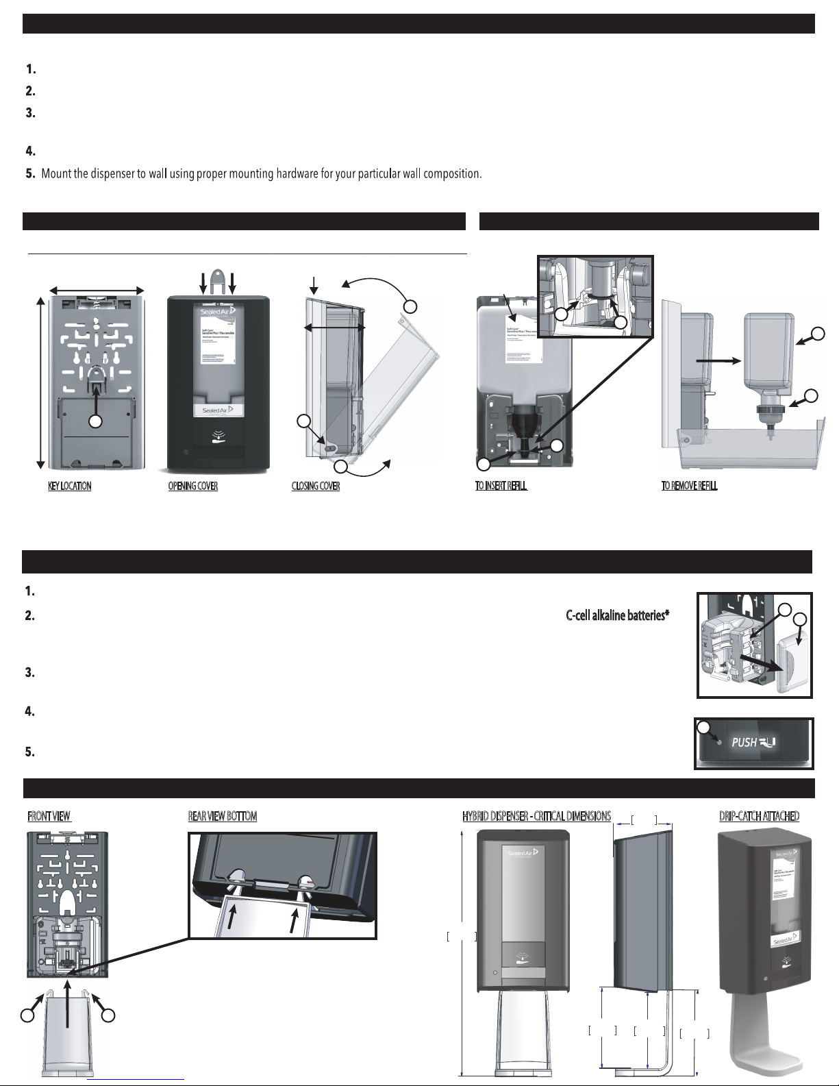
1.3 REFILL PLACEMENT & REMOVAL
Insert Sealed Air key (or other item that ts the key hole) at top of cover and pull cover. You now have access to Electronic Module and Batteries.
The dispenser will turn “on” automatically once batteries are installed. You will get a quick ash of the PUSH icon (x-2) followed immediately by a
ash of the GREEN LED (c) indicating the unit is functional.
Remove the battery cover (’a’ - by PULLING cover toward the front) located on the right side of the module (see x-1). Insert 4 C-cell alkaline batteries*
(not included) making sure to place the batteries in the proper orientation as shown by the diagram in the battery compartment (b).
Replace the battery cover.
*(Rechargeable batteries are not to be used. Do not use different types of batteries. New and used batteries are not to be mixed.)
If replacing soap dispenser on wall, determine if any of the holes match up on the Sealed Air unit. Unit designed to at least partially match numerous soap dispensers.
11.13”
(282mm)
6.256”
(158mm)
1.5 OPTIONAL DRIP-CATCH INSTALLATION
x-1 REMOVING BATTERY COVER
IMPORTANT
LABEL FACES OUT
NOTE: Low Refill counter will NOT be affected when changing batteries.
x-2 MANUAL MODE PUSH ICON
FRONT VIEW DRIP-CATCH ATTACHEDREAR VIEW BOTTOM HYBRID DISPENSER - CRITICAL DIMENSIONS
‘click’
g.
h.
a.
When the batteries become too low for the dispenser to function, the “PUSH” icon will illuminate conveying the unit to be used in manual
mode (see x-2) and indicates that the batteries need to be replaced.
Remove key from back of housing. (Reference‘Key Location’ in section 1.2, below)
If an object remains in the dispenser infrared (IR) sensing range for more than 10 seconds, the white 'PUSH the COVER' decal and GREEN LED will blink and no soap will be
dispensed. Once the object is NO longer in 'view' of the IR (at bottom of dispenser), the dispenser will operate normally.
The dispenser should be mounted at least 12 inches (30.5cm) above the counter-top, sink or other surface.
1.2 DIMENSIONS, KEY LOCATION,OPENING & CLOSING DISPENSER
**KEY OUTER DIMENSIONS OF DISPENSER : (H)11.13” [282MM] x (W)6.256” [158MM] x (D)4” [101.6mm]
Remove cover key (a) from
back of housing.
To close the cover, pull cover from bottom (b) so
that bottom hinge (c) is pulled all the way OUT,
then PUSH the top of cover closed to ‘click’ shut (d).
Insert key in to holes
on top of cover. Pull
cover forward to open.
Push rell in to place to ensure the FLANGE of the
Soap Nozzle (e) is seated into the correct location (f).
If not, the dispenser will not pump correctly.
TO INSERT REFILL TO REMOVE REFILL
Pull the Container (g) and the Pump
Housing (h). Please recycle accordingly.
OPENING COVERKEY LOCATION CLOSING COVER
1.1 MOUNTING DISPENSER
NOTE: SEE KEY DISPENSER DIMENSIONS BELOW (1.2). IF INSTALLING WITH DRIP-CATCH, SEE CRITICAL DIMENSIONS BELOW (1.5)
1.4 BATTERY INSTALLATION
f.
b.
pull
d.
push
pull
f.
e.
e.
b. a.
c.
5.916
150.28
16.38
416.09
5.61
142.38
5.25
133.26
NOTE:
The Drip Catch is not designed to be removed.
However, if going to remove for cleaning please be careful
not to damage the dispenser. The drip catch also might
be damaged after removing.
DISCLAIMER:
If other drip catch used, Sealed Air not responsible for damage.
Insert drip catch hooks (a) through rectangular
slots located at the bottom rear of the dispenser.
The Drip-Catch with SNAP into place.
c.
a. a.
101.6
4.0
4”
(101.6mm)
Exhausted batteries are to be removed from the dispenser and safely disposed of. If the dispenser is to be stored unused for a long period of time,
remove the batteries.
NOTE : TAPE & SCREWS/ANCHORS ARE PROVIDED. DISCLAIMER :
If rells (Soap) used other than certied SA soap, SA is not responsible for any dispenser issues.
Go to section 3.0 for specic dispenser mounting instructions.
1B : BLINKING GREEN LED with
ALTERNATING PUSH ICON BLINK (#3)
Object in View more than 10 seconds
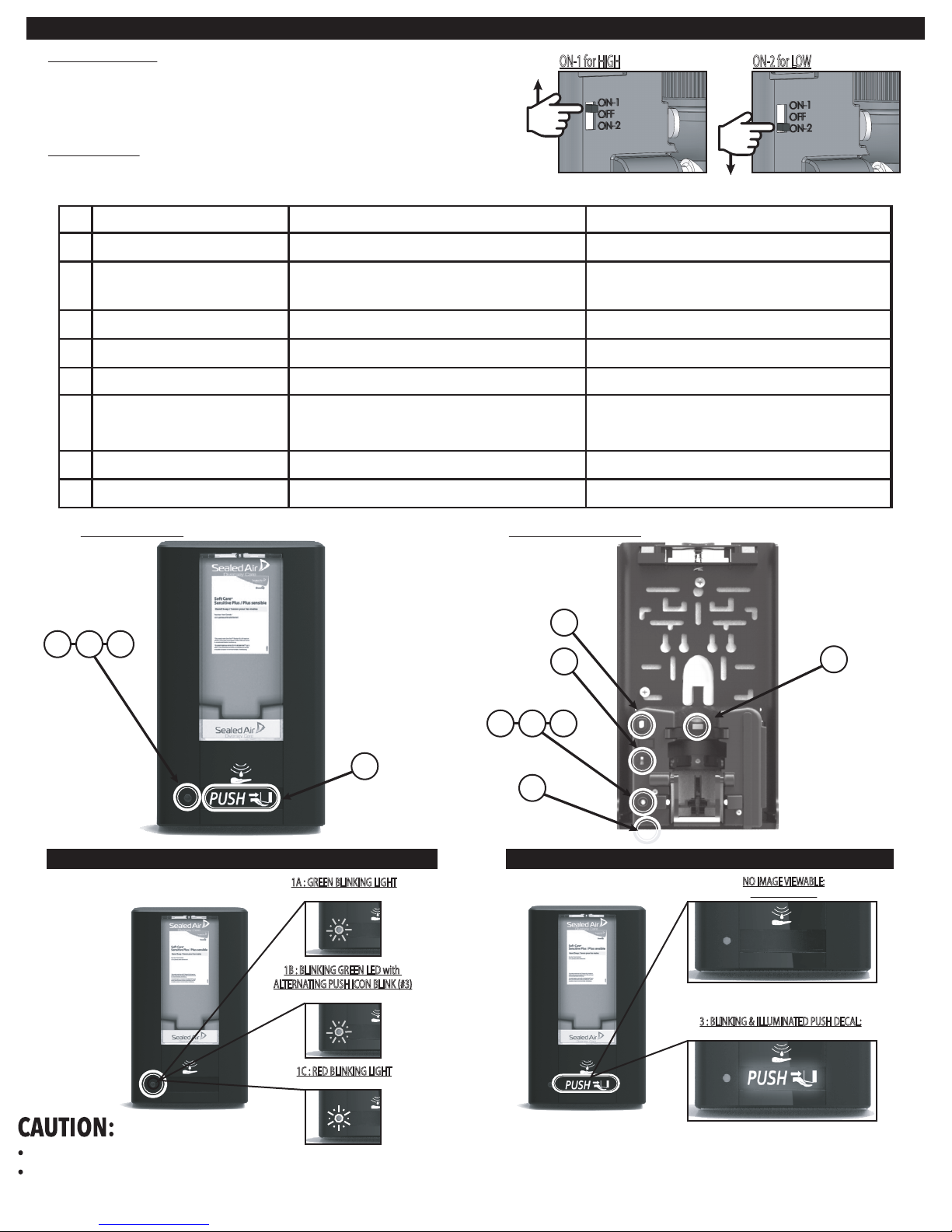
Power indicator1A
1B
1C
2
3
Low Rell Indicator RED LED blinks every 1 Second
Object In View Indicator Alternating GREEN Blink with Blinking of
'Low Battery Indicator' (#3)
Object in VIEW of dispenser for MORE than 10 Seconds.
Remove object to re-start dosing.
Blinking Green LED (every 3 sec)
Control Dose Amount per Use
Rell is Low
Standby mode, dispenser waiting to be used
ON / OFF & Dose Control Switch
Low Batttery Indicator Blinking Illuminating“PUSH”decal Batteries LOW / Install New Batteries
Activated when Rell Inserted Each time rell inserted, the DOSE Count begins to ensure
Low Rell Indicator (1C) blinks at the appropriate time
4Rell Counter Switch (RED)
Extends when Cover Open Ensures that NO product is dosed when cover is OPEN
5 Cover Open Switch (RED)
Senses Hand to Automatically Dose Soap Keep Clean
6 IR Lens
Electronic Component and LED (Light) Explanation (see corresponding images below the matrix for further clarification)
#ELECTRONIC COMPONENT ACTION DESCRIPTION
Front Cover View
Electronic Dosing:
Manual Dosing:
Inside Dispenser View
ELBOW BAR INSTALLATION STEPS
2.2 POWER & LOW REFILL INDICATOR 2.3 LOW BATTERY INDICATOR
1A : GREEN BLINKING LIGHT
Dispenser ON and Functioning
NO IMAGE VIEWABLE:
Batteries are Good
3 : BLINKING & ILLUMINATED PUSH DECAL:
Batteries Need Replacement
1A 4
2
1B 1C
1A 1B 1C
5
2.1 ELECTRONIC SET UP, ACTIVATION & EXPLANATION
To activate dispenser in manual mode; push the bottom, center of the cover.
The supply terminals are not to be short-circuited.
Keep the IR lens clean.
1C : RED BLINKING LIGHT
Rell Low
6
3
A.
B.
C.
Instructions are provided for safe use of the dispenser.
This dispenser can be used by children aged from 8 years and above and persons with reduced physical, sensory and mental capabilities or lack of experience and knowledge if they have been given
supervision or instruction concerning use of the dispenser in a safe way and understand the hazards involved. Children shall not play with the dispenser. Cleaning and user maintenance shall not be
made by children without supervision.
ON - 1: FOR HIGH / ON - 2: FOR LOW
Choose size of dose required (ON-1 for HIGH or ON-2 for LOW). See images to the right.
ON-1 for HIGH ON-2 for LOW

3.0 DISPENSER MOUNTING INSTRUCTIONS
Ensure the Key is removed from the housing. See Step 1 under 3.1 Below.
Mount the dispenser to wall using proper mounting hardware for your particular wall composition.
See 3.1 (Tape Mounting Instructions) and 3.2 (Screw Mounting Instructions)
If replacing soap dispenser on wall, determine if any of the holes match up on the Sealed Air unit.
Unit is designed to at least partially match numerous soap dispensers.
The dispenser should be mounted
12” (30.5 CM) above the counter-top,
sink or other surface. If an object
remains in the sensing range for
more than 10 seconds, the white and
green LED will begin blinking and
no soap will be dispensed after the
initial dose. Remove object and
unit will operate normally.
5.
MIN
12”
30.5 CM
3.2 SCREW MOUNTING INSTRUCTIONS
3.1TAPE MOUNTING INSTRUCTIONS
STEP 1 STEP 2
STEP 1 STEP 2A STEP 2B
Step 1: The Dispenser housing
provides numerous mounting
locations. If replacing a
competitive unit,determine
if one (or more) of the
holes match.
If no holes exist on wall or do not
properly match, we suggest using
the three holes circled above.
NOTE: Ensure that proper
mounting hardware is used
for your particular
wall composition.
Step 3: Insert the washers over the
screwsand then use a screwdriver to
insert the screws in to the anchors
and tighten the dispenser
securely against the wall.
+
STEP 3
7/32" (6 MM)
Drill Bit
NOTE: Tape can be used effectively for installations on mirrors and tile.
91-00005_Rev13
Step 2B: Insert anchors into
all three holes.
Step 2A: Use a 7/32" (6 MM)
drill bit to bore the holes on
the wall for the anchors,washers
and screws provided.
15-20 SEC.
PRESS
Step 2: Remove the red backing from
the tape. Ensure that the dispenser is in a
level position on the wall,open cover and
press the dispenser firmly for 15 to 20
seconds to allow it to properly
adhere to wall.
It's recommended to let the dispenser set up
for 24 hours before installing the refill.
*IMPORTANT
Step 1:Tape mounting is recommended for
mirror installations.
For tile or other wall installations,
anchor & screw mounting is recommended
If tape mounting is the only option,
thoroughly clean the mounting surface using
the supplied alcohol wipe and make sure all
dirt, grease and surface film is removed.
After cleaning, ensure the mounting surface
is given time to completely dry,or wipe dry
with a clean paper towel before attaching
the dispenser to the wall.
Table of contents
Other Sealed Air Dispenser manuals


