Henkel Loctite RB10 User manual

1
EQUIPMENT
Operation Manual
LoctiteRB10 Rotary Dispense System
Part Number 1635546

2
Table of Contents
1Please Observe The Following 3
1.1 Emphasized Sections 3
1.2 For Your Safety
1.3 Inspection 3
1.4 Items Supplied 4
1.5 Features 4
2 Description 4
2.1 Control Panel 4
2.2 Integration Panel 5
3 Technical Data 5
4 Installation 6
5 Operation 7
5.1 Theory of Operation 7
5.2 Controller Set Up 8
5.3 Mounting Plate 10
5.4 Valve and Syringe Dispenser Integration 11
5.4.1 Light Cure, CA and VA10 Valves 11
5.4.2 Stationary Valves 11
5.4.3 Syringe or Cartridge Dispensing 12
5.5 Slide Adjustment 13
5.6 Reservoir Low Level Control 13
6 Troubleshooting 14
7 Care and Maintenance 14
8 Accessories 15
9 Wiring Schematic 15
10 Warranty 16

3
1 Please Observe The Following
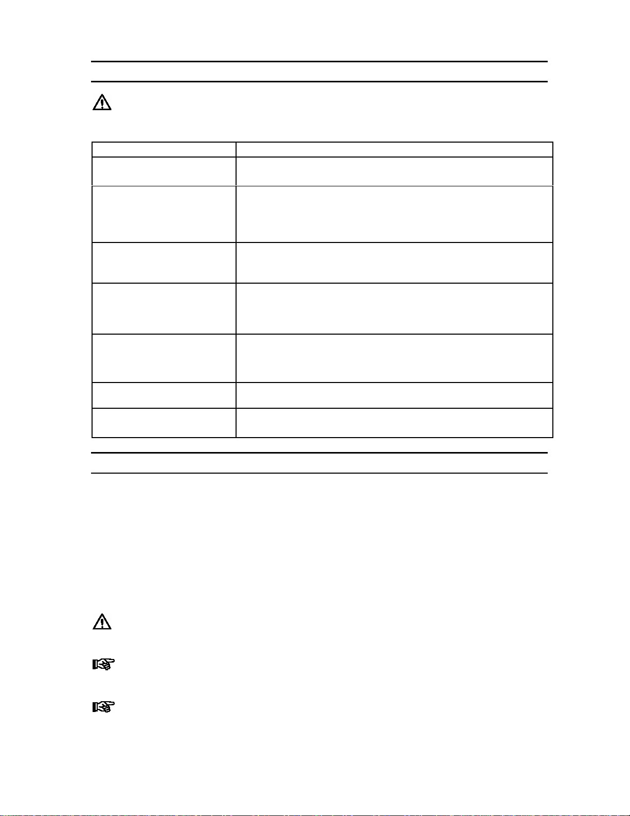
1.1 Emphasized Sections
Warning!
Refers to safety regulations and requires safety measures that protect the operator or
other persons from injury or danger to life.
Caution!
Emphasizes what must be done or avoided so that the unit or other property is not
damaged.
Notice:
Gives recommendations for better handling of the unit during operation or
adjustment as well as for service activities.
1.2 For Your Safety
For safe and successful operation of the unit, read these instructions
completely. If the instructions are not observed, the manufacturer can assume no
responsibility.
Do not expose the connecting cable to heat, oil, or sharp edges.
Make sure the Unit stands stable and secure.
Use only original equipment replacement parts.
Always disconnect the power supply before servicing the unit.
Observe general safety regulations for the handling of chemicals such as
Loctite®adhesives and sealants. Observe the manufacturer’s instructions as stated
in the Material Safety Data Sheet (MSDS).
While under warranty, the unit may be repaired only by an authorized Loctite service
representative.
1.3 Unpacking and Inspection
Carefully unpack the Loctite®RB10 Rotary Dispense System and examine the
items contained in the carton. Inspect the unit for any damage that might have
occurred in transit. If such damage has occurred, notify the carrier immediately.
Claims for damage must be made by the consignee to the carrier and should be
reported to the manufacturer.

4
1.4 Items supplied
(1) Rotary Dispense System
(1) Foot Switch
(1) Power Supply with Cord
(1) Instruction Manual
1.5 Features
Integrated Solution –plug and play with Loctite valves, reservoirs, and
Syringe Systems
Digital Control of rotation, dispense start, dispense stop and delays
Adjustable height, position, angle of dispense, and advance slide speed
Reservoir low-level interface with cycle interruption and display message
Part position sensing allows orientation of adhesive bead start and end
Threaded and non threaded mounting holes for fixtures
Operator lockout for supervisory control of settings
Dispense valve and syringe mounting hardware available
2 Description
The Loctite®RB10 Rotary Dispense System is a fully integrated system used for
dispensing adhesives onto parts in a circular or arc pattern. It will control a syringe system,
cartridge, or dispense valve without requiring a separate valve controller. Internally
synchronized operation of an advancing slide, turntable, and dispense timer makes for easy
and repetitive placement of the adhesive. The set-up is simple, using only preset distance
and rotation speed adjustment. No complex programming required!
2.1 Control Panel (Front of Controller)

5
2.2 Integration Panel (Back of Controller)
3 Technical Data
Attribute Value
Dispense Pattern Circles or Arcs in a Circular Pattern
Slide Stroke 0 –2”(0 –50 mm)
Rotation Range 0 –999 Degrees
Rotation Speed 5 to 55 RPM
Maximum Part Height 12”(305 mm)
Maximum Part Diameter 18”(475 mm)
Maximum Part Weight 6 lbs (2.7 kg)
Width 12”(305 mm)
Depth 8¾”(222 mm)
Dimensions
Height 22”(559 mm) Minimum
25”(635 mm) Maximum
Weight 18.5 lb (8.4 kg)
Air Input*Clean, dry air not to exceed 125 psig (8.5 bar),
and filtered with a maximum of 50 micron
Power Supply: 110 –230 V / 50 –60 Hz
Internal: 24 VDC
* If the required air quality is not available, install a Loctite®filter regulator. In the US order a
5m filter using part number 985397. In Europe or Asia, order a 10 m filter using part
number 97120.

6
4 Installation
Before using the tool for the first time check it carefully for signs of external
damage. If any shipping damage is found DO NOT USE THE TOOL - return it to
your supplier immediately.
1. Assemblethe standtothemaincontrolunit byattaching theverticalmountingpole(the
longerbarsupplied)intotheverticalsupport bracketonthecontroloftheunit. Tighten
theM4 fromthesideofthesupport brackettosecure theverticalmountingpole.
2. Assemblethe slide assemblytothestand.
3. SecuretheslideassemblybytighteningtheM6 screwontheslide assemblybracket.
4. Connect the Cylinder Extend and Cylinder Retract Air hoses to the Cyl Extend
and Cyl Retract ports on the back of the unit.
5. Connect the Advance Slide Cable to the Advance Slice Limit Switch connector
of the back of the unit.
6. Plugthepower adapterwithcordintothe“24VDC”inputonthebackofthecontrollerand
intothewallsocket.
Notice: The power adapter has auto ranging power function that can be used
with either 110 or 220V and 50 or 60 Hz.
7. Connectthefootswitch,orPLCstartsignalcable,tothe“StartSwitchXS1”connectoron
thebackofthecontroller.
8. Connecttheairinputlineto theAirInputfittingusing6mmO.D.pneumatictubing(not
supplied).
9. Turn on the local airsupply. This must be a minimum of 80 psi anda maximum of 125
psi.
Warning! When the air is connected, the slide may retract. Be sure to keep
your hands and other objects clear of the slide before connecting the air.
Caution! Clean, dry, filtered air must be used. If it is not, the solenoids in the
controller will be fouled over time. If the required air quality is not achieved,
install a Loctite®filter regulator. In the US order a 5 m filter using Part Number
985397. In Europe or Asia, order a 10 m filter using Part Number 97120.

7
5 Operation
5.1 Theory of Operation
1. After turning on the unit, press the footswitch or ENTER button to activate the
system.
2. The advancing slide will start to extend and the rotary disc will start to rotate with
the preset speed.
3. The advancing slide will activate the proximity sensor when it reaches the preset
position.
4. The start of disc rotation, or the locator pin reaching the proximity sensor (in
homing mode), will trigger the rotation distance counter and the unit will start to
dispense for preset dispensing time. Use of the homing mode ensures that each
dispense start will be at the same point.
5. After the dispensing timer has reached the preset dispense time, the advancing slide
will retract and the rotary disc will be stopped.
6. The dispense start position “DS Position”determines how far the disc will rotate
before starting to dispense. This ensures the rotation has reached a constant speed
when dispense begins.
7. The “Off Delay”feature determines how long the disc will continue to rotate after
the dispense has stopped. This allows product remaining on the tip of the dispenser
to be transferred to the part after the dispense stops, prior to retracting.
8. The reservoir low level sensor setting disables the start signal and displays “Alarm:
RESERVOIR LOW LEVER.”The Low Level state can be manually overridden
allowing the system to cycle by pressing the ENTER button, however the alarm will
continue to be displayed and the system will not cycle using a footswitch or PLC.

8
5.2 Controller Set Up
Display
Step
Enter
To Unlock Press 1 & 3
Together For Three Seconds Toggle
Notice: Upon start-up, the system will be in operator lockout mode.
To unlock the controller, press 1 & 3 simultaneously for three seconds. To return to
operator lockout mode simply turn system off; all settings will be stored. The system will
always start in operator lockout mode.
The Display at Power ON will be:
READY
press START
Unlock the controller by pressing 1 & 3 simultaneously for three seconds.
The Display will still be:
READY
press START
Press Step and the Display will change to
LOW LEVEL SENSOR
enabled
To disable the low level sensor, press the Toggle Arrow then press ENTER
Press Step and the Display will change to
HOMING
OFF
To enable homing, press the Toggle Arrow then press ENTER

9
Press Step and the Display will change to
Speed: 10 RPM
Dist: 90 deg
To change the speed (revolutions per minute), type the desired speed with key pad,
then press ENTER
To change the distance (in degrees) that product will dispense, type the desired
distance using the key pad, then press ENTER
Notice: The distance setting determines how far the rotation motor receives power
and is intended to be an aid in initial set up not as an absolute setting of rotation. Higher
speed setting and heavier part weights create momentum that will cause mounting plate to
carry beyond the preset degrees in a repeatable fashion.
Press Step and the Display will change to
DS Position: 0
OFF Delays: 0.0
To set the Dispense Start position (how far the disc will rotate before dispense
starts) type the desired distance, in degrees, then press ENTER
To set the desire off delay (how long in seconds the disc will rotate after dispense
stops, type the desired time then press ENTER
Press Step and the Display will change to
READY
press START
You have completed Controller Set Up. The Controller will remain unlocked until power
is turned off.
Notice: The settings can be tested without exiting mode by pressing 1 & ENTER.
This will start a cycle.
Changes can be made by pressing STEP key until you get to the desired parameter.
To save the changes and exit Program Mode, simply turn the power off.

10
5.3 Mounting Plate
The drawing below shows the RB10 Rotary Dispense System mounting plate. This
through holes on the mounting plate can be used for fixture alignment and the threaded ¼-
20 holes can be used to secure the fixture.

11
5.4 Valve and Syringe Dispenser Integration
The Loctite®RB10 Rotary Dispense System is designed to be used with syringes, cartridges,
single acting product valves and double acting product valves. To integrate these dispense
systems please use the following instructions:
5.4.1 98009 Light Cure, 98013 Cyanoacrylate and VA10 Micro Dispense Valves
Must be purchased separately:
Mounting Rail –P/N98328
Mounting Bracket –P/N98326
Mounting Bracket –P/N1638885
PressureReservoir
- P/N 982726,Bond-A-Matic reservoir,0-15psi for use withadhesives with <3,000cPs viscosity.
- P/N 982727,Bond-A-Matic reservoir,0-100 psi for use with adhesives with >3,000 cPs viscosity.
1. Insertthe4mm tubeplugin the upper“DispenseOut”(normallyclosed) connection.
2. Addthedispensetip onto thevalve.
3. Secure themounting rail to the advance slideusingthe M4 screws provided.
4. Slidethemounting bracketoverthemountingrail ontheslideassemblyandsecureit in
position withthewhite nylonthumbscrew.
5. Manuallypullthe slide downto thefullyextendedposition.
6. Slidethevalveintothemountingbracketandsecure it usingtheblack thumbscrews.
7. Adjust the height andpositionofthemounting brackettothe approximate positiondesired.
Toadjusttheposition, loosenthescrews on theclamp blockscounter clockwise,setthe
position andthensecurebyturningthescrewsclockwise.
Caution! It is important to ensure that the dispense tip will not crash with the
mounting plate, fixture or part. Please ensure that the height is set to avoid crashes.
8. Connecttheairinletonthevalvetotheupper“DispenseOut”on the back ofthecontroller
usingthe4mmairlinetubingsupplied withthevalve.
5.4.2 97113 and 97114 Stationary Valves
Must be purchased separately:
Mounting Rail –P/N98328
Mounting bracket–P/N98327
PressureReservoir
- P/N 982726,Bond-A-Matic reservoir,0-15psi for use withadhesives with <3,000cPs viscosity.
- P/N 982727,Bond-A-Matic reservoir,0-100 psi for use with adhesives with >3,000 cPs viscosity.
- P/N982720, Bond-A-Maticreservoir,0-15psi, withlowlevelsensor.
- P/N982723, Bond-A-Maticreservoir,0-100psi,withlowlevel sensor.
1. Using 4mmtubingsuppliedwiththevalve, connect boththe upper“DispenseOut”
(normallyclosed)andlower“DispenseOut”(normallyopen)connectionsfrom the valve
to theback ofthecontroller.
2. Addthedispensetip tothe valve.
3. Secure themounting rail to the advance slideusingthe screws provided with the bracket.
4. Slidethemounting bracketoverthemountingrail ontheslideassemblyandsecureit in
position withthewhite nylonthumbscrew.
5. Manuallypullthe slide downto thefullyextendedposition.
6. Slidethevalveintothemountingbracketandsecure it usingtheblack thumbscrews.

12
7. Adjust the height andpositionofthemounting brackettothe approximate position
desired. Toadjusttheposition,loosenthescrews ontheclampblockscounterclockwise,
setthe positionandthensecure byturningthescrews clockwise.
Caution! It is important to ensure that the dispense tip will not crash with the
mounting plate, fixture or part. Please ensure that the height is set to avoid
crashes.
5.4.3 Syringe or Cartridge Dispensing
Must be purchased separately:
Loctite Part Number
Syringe CartridgeAccessory 10 ml 30 ml 55 ml 300 ml
Syringe Dispenser (Required) 883976 883976 883976 883976
3 ¾”Mounting Rail (required) 98328 98328 98328 98328
Mounting Bracket (required) 98316 98316 98316 98318
Syringe Adapter (required) 98320 N/A N/A N/A
Dispense Tip Connectors (required) N/A N/A N/A 982644
97233
Clear Syringe Barrel Kit (optional) 97207 97244 98314 N/A
Black Syringe Barrel Kit (optional) 97263 97264 98315 N/A
1. Refer to the operation manualofthesyringedispenserforsetupinstructions.
2. Connectthesyringedispenser tothesystemwithXS2cable partnumber 989432(need
to purchaseseparately).
3. Insertthe4mm tubeplugin the both theupper “DispenseOut”(normallyclosed) and lower
“DispenseOut”(normallyopen) connections.
4. Addthe dispensetip ontothesyringeor cartridge. Forsome cartridges, itwill be
necessarytoinstall thecartridge adapterPartNo. 982644and luerlock adapterPartNo.
97233beforeconnectingthe dispensetip.
5. Secure themounting rail to the advance slideusingthe M4 screws provided.
6. Slidethemounting bracketoverthemountingrail ontheslideassemblyandsecureit in
position withthewhite nylonthumbscrew.
7. Manuallypullthe slide downto thefullyextendedposition.
8. Adjust the height andpositionofthemounting brackettothe approximate position
desired. Toadjusttheposition,loosenthescrews ontheclampblockscounterclockwise,
setthe positionandthensecure byturningthescrews clockwise.
9. Slidethesyringe or cartridgeinto the mountingbracket andsecure itusingtheblack
thumbscrews.
Caution! It is important to ensure that the dispense tip will not crash with the
mounting plate, fixture or part. Please ensure that the height is set to avoid
crashes.

13
5.5 Slide Adjustments
The speed controls on the slide can be adjusted to increase or decrease the speed that the
slide advances or retracts. The speed should be set so that the slide moves at a controlled
rate. This may need to be adjusted to account for more weight on the slide or to change the
slide advance / retract time.
5.6 Reservoir Low Level Control
5.6.1 Disabling the Low Level Function
1. In Set Up mode (see section 5.2) set Low Level Sensor to “Disabled.”
5.6.2 Enabling the Low Level Function
1. Connect the 9 pins D-sub female (XS2 Low Lev) cable the to the Low Level Sensor
(XS2) Connector.
2. In Set Up mode (see section 5.2) set Low Level Sensor to “Enabled.”
Notice: When a Reservoir Low Level state occurs during a cycle, the cycle will
complete and the display will read “Alarm: RESERVOIR LOW LEVER.”The Low
Level setting disables the start signal.
Notice: In run mode, the Low Level state can be manually overridden allowing the
system to cycles by pressing the ENTER button. Pressing the ENTER button will cycle the
unit, however the alarm will continue to be displayed and the system will not cycle using a
footswitch or PLC.
Notice: In Set Up mode, pressing the ENTER button will clear the Low Level state
for one cycle fully disabling the alarm and allowing use of the foot switch or PLC.
3. After eliminate the Low Level state, pressing ENTER will run another cycle and
reset the Low Level alarm. The Low Level alarm can also be re-set by turning the
system off after eliminating the Low Level state.
Adjust Slide Advance
Rate Here
Adjust Slide Retract
Rate Here
14
6 Troubleshooting
Before proceeding with any repair or maintenance operation disconnect the
tool from the main electricity supply.
Symptom Possible Corrective Action(s)
Plug the unit inThe “POWER”does not turn
“ON” Set the “POWER”button “ON”position
1. Confirm that the “Air Input”is connected
2. Confirm that the air supply is 80-125 psi.
The system will not pressurize.
3. Confirm that the “Dispense Out”fittings are properly connected or
plugged.
Mounting plate rotates further
than distance setting. Higher speeds and part weights will cause the mounting plate to carry
beyond the distance setting. The distance setting is intended for reference
purposes only as an aid to initial set up.
The slide is advancing or
retracting too fast or slow. The slide advance and retract rate should be set so that the slide moves at a
controlled rate. The factory default is for the full slide stroke to take
approximately 0.5 seconds. If this needed to be adjusted, see Section 5.5
for instructions.
1. Confirm that the air supply is pressurized and at 80-125 psi.The disc will not stop rotating
and the display reads
“Homing… ”OR
Display read "Dispenser in wait"
2. Confirm that the advancing slide moves down when the cycle starts.
1. Check that XS2 cable between the reservoir and the RB10 is connected.The “Reservoir Low Level
Alarm Light”(1) does not work 2. Check that Low Level Sensor Switch setting is in the “enabled”state.
1. Check the pneumatic connection.The dispense valve does not
dispense 2. Check the pneumatic supply.
7 Care and Maintenance
7.1 Care
This unit should be stored in a level, dry location at ambient condition out of direct
sunlight.
7.2 Maintenance
To minimize wear of the slide assembly, periodically apply several drops of light machine
oil to the slide rods, manually advance and retract the slide several times then remove the
excess lubricant using a rag.
Warning! Be sure to release the pressure and shut of the pressure supply before
lubricating the slide rods.
Notice: Clean, dry, filtered air must be used. If it is not, the solenoids on the
controller will be fouled over time.
Notice: If the required air quality is not achieved, install a Loctite®filter regulator.
In the US order a 5 m filter using Part Number 985397. In Europe or Asia, order a 10 m
filter using Part Number 97120.

15
8 Accessories
Syringe Dispenser Accessories:
Loctite Part Number
Syringe CartridgeAccessory 10 ml 30 ml 55 ml 300 ml
Syringe Dispenser (Required) 883976 883976 883976 883976
3 ¾”Mounting Rail (required) 98328 98328 98328 98328
Mounting Bracket (required) 98316 98316 98316 98318
Syringe Adapter (required) 98320 N/A N/A N/A
Dispense Tip Connectors (required) N/A N/A N/A 982644
97233
Clear Syringe Barrel Kit (optional) 97207 97244 98314 N/A
Black Syringe Barrel Kit (optional) 97263 97264 98315 N/A
Additional Mounting Hardware:
Description Item Number
98009 and 98013 Valve Mounting Bracket 98326
97113 and 97114 Valve Mounting Bracket 98327
VA10 Valve Mounting Bracket 1638885
3 3/4 inch mounting rail with two cap screws 98328
8 3/4 inch mounting rail with two cap screws 98329
C Rail Kit for Mounting Brackets 98331
986300 Poppet Valve Mounting Bracket Kit 98406
98084 or 98520 Valve Mounting Bracket Kit 98441
9 Wiring Schematic

16
10 Warranty
Henkel expressly warrants that all products referred to in this Instruction Manual for 1635546 LoctiteRB10
Rotary Dispense System (hereafter called “Products”) shall be free from defects in materials and
workmanship. Liability for Henkel shall be limited, as its option, to replacing those Products which are shown
to be defective in either materials or workmanship or to credit the purchaser the amount of the purchase price
thereof (plus freight and insurance charges paid therefor by the user). The purchaser’s sole and exclusive
remedy for breach of warranty shall be such replacement or credit.
A claim of defect in materials or workmanship in any Products shall be allowed only when it is submitted in
writing within one month after discovery of the defect or after the time the defect should reasonably have
been discovered and in any event, within (12) months after the delivery of the Products to the purchaser. This
warranty does not apply to perishable items, such as fuses. No such claim shall be allowed in respect of
products which have been neglected or improperly stored, transported, handled, installed, connected,
operated, used or maintained. In the event of unauthorized modification of the Products including, where
products, parts or attachments for use in connection with the Products are available from Henkel, the use of
products, parts or attachments which are not manufactured by Henkel, no claim shall be allowed.
No Products shall be returned to Henkel for any reason without prior written approval from Henkel. Products
shall be returned freight prepaid, in accordance with instructions from Henkel.
NO WARRANTY IS EXTENDED TO ANY EQUIPMENT WHICH HAS BEEN ALTERED, MISUSED,
NEGLECTED, OR DAMAGED BY ACCIDENT.
EXCEPT FOR THE EXPRESS WARRANTY CONTAINED IN THIS SECTION, HENKEL MAKES NO
WARRANTY OF ANY KIND WHATSOEVER, EXPRESS OR IMPLIED, WITH RESPECT TO THE
PRODUCTS.
ALL WARRANTIES OF MERCHANTABILITY, FITNESS FOR A PARTICULAR PURPOSE, AND
OTHER WARRANTIES OF WHATEVER KIND (INCLUDING AGAINST PATENT OR TRADEMARK
INFRINGEMENT) ARE HEREBY DISCLAIMED BY HENKEL AND WAIVED BY THE PURCHASER.
THIS SECTION SETS FORTH EXCLUSIVELY ALL OF LIABILITY FOR HENKEL TO THE
PURCHASER IN CONTRACT, IN TORT OR OTHERWISE IN THE EVENT OF DEFECTIVE
PRODUCTS.
WITHOUT LIMITATION OF THE FOREGOING, TO THE FULLEST EXTENT POSSIBLE UNDER
APPLICABLE LAWS, HENKEL EXPRESSLY DISCLAIMS ANY LIABILITY WHATSOEVER FOR
ANY DAMAGES INCURRED DIRECTLY OR INDIRECTLY IN CONNECTION WITH THE SALE OR
USE OF, OR OTHERWISE IN CONNECTION WITH, THE PRODUCTS, INCLUDING, WITHOUT
LIMITATION, LOSS OF PROFITS AND SPECIAL, INDIRECT OR CONSEQUENTIAL DAMAGES,
WHETHER CAUSED BY NEGLIGENCE FROM HENKEL OR OTHERWISE.
Henkel Corporation
One Henkel Way
Rocky Hill, CT 06067-3910
Henkel Canada Corporation
2225 Meadowpine Boulevard
Mississauga, Ontario L5N 7P2
Henkel Capital, S.A. de C.V.
Calzada de la Viga s/n Fracc. Los Laureles
Loc. Tulpetlac, C.P. 55090
Ecatepac de Morelos, Edo. de México
Henkel Corporation
Automotive / Metals HQ
32100 Stephenson Hwy.
Madison Heights, MI 48071
Henkel Ltda.
Rua Karl Huller, 136 –Jd.
Canhema 09941-410
Diadema/SP, Brazil www.loctite.com
® and ™designate trademarks of Henkel Corporation or its affiliates. ® = registered in the U.S. and elsewhere. © Henkel Corporation,
2009. All rights reserved. Data in this operation manual is subject to change without notice.
Manual P/N: 8903134, Rev A, Date: 08/13/2012
This manual suits for next models
1
Table of contents
Other Henkel Dispenser manuals

Henkel
Henkel Loctite 98427 User manual

Henkel
Henkel Loctite 98548 User manual

Henkel
Henkel Loctite Shot Miser User manual

Henkel
Henkel Loctite 97631 User manual

Henkel
Henkel Loctite EQ HD12 manual

Henkel
Henkel Loctite User manual

Henkel
Henkel LOCTITE 97130 User manual

Henkel
Henkel Loctite 97008 User manual

Henkel
Henkel OSI Service manual

Henkel
Henkel Loctite EQ RC40 User manual


