manuals.online logo
Brands
  1. Home
  2. •
  3. Brands
  4. •
  5. Sealey
  6. •
  7. Air Compressor
  8. •
  9. Sealey SA4025/3.V3 User manual

Sealey SA4025/3.V3 User manual

INSTRUCTIONS FOR:
QUIET RUNNING COMPRESSOR
3.0hp, 230V
MODEL No: SA4025/3.V3
Thank you for purchasing a Sealey product. Manufactured to a high standard this product will, if used according to these instructions
and properly maintained, give you years of trouble free performance.
1. SAFETY INSTRUCTIONS
IMPORTANT: PLEASE READ THESE INSTRUCTIONS CAREFULLY. NOTE THE SAFE OPERATIONAL REQUIREMENTS, WARNINGS AND CAUTIONS.
USE THE PRODUCT CORRECTLY AND WITH CARE FOR THE PURPOSE FOR WHICH IT IS INTENDED. FAILURE TO DO SO MAY CAUSE
DAMAGE AND/OR PERSONAL INJURY AND WILL INVALIDATE THE WARRANTY. PLEASE KEEP INSTRUCTIONS SAFE FOR FUTURE USE.
1.1. ELECTRICAL SAFETY. WARNING! It is the user’s responsibility to read, understand and comply with the following:
You must check all electrical equipment and appliances to ensure they are safe before using. You must inspect power supply leads, plugs and
all electrical connections for wear or damage. You must ensure the risk of electric shock is minimised by the installation of appropriate safety
devices. An RCCB (Residual Current Circuit Breaker) should be incorporated in the main distribution board. We also recommend that an RCD
(Residual Current Device) is used with all electrical products. It is particularly important to use an RCD with portable products that are plugged
into an electrical supply not protected by an RCCB. If in doubt consult a qualified electrician. You may obtain a Residual Current Device by
contacting your Sealey dealer. You must also read and understand the following instructions concerning electrical safety.
1.1.1. The Electricity At Work Act 1989 requires all portable electrical appliances, if used on business premises, to be tested by
a qualified electrician, using a Portable Appliance Tester (PAT), at least once a year.
1.1.2. The Health & Safety at Work Act 1974 makes owners of electrical appliances responsible for the safe condition of those appliances
and the safety of appliance operators. If in any doubt about electrical safety, contact a qualified electrician.
1.1.3. Ensure the insulation on all cables and the product itself is safe before connecting to the mains power supply.
See 1.1.1. & 1.1.2. above and use a Portable Appliance Tester (PAT).
1.1.4. Ensure that cables are always protected against short circuit and overload.
1.1.5. Regularly inspect power supply leads and plugs for wear or damage and connections to ensure that none is loose.
1.1.6. Important: Ensure the voltage marked on the product is the same as the electrical power supply to be used, and check that plugs are
fitted with the correct capacity fuse.
1.1.7. DO NOT pull or carry the powered appliance by its power supply lead.
1.1.8. DO NOT pull power plugs from sockets by the power cable.
1.1.9. DO NOT use worn or damage leads, plugs or connections. Immediately replace or have repaired by a
qualified electrician.
1.1.10. A U.K. 3 pin plug with ASTA/BS approval is fitted. In case of damage, cut off and fit a new plug
according
to the following instructions (UK only - see diagram at right). Discard old plug safely.
Ensure the unit is correctly earthed via a three-pin plug.
a) Connect the green/yellow earth wire to the earth terminal ‘E’.
b) Connect the brown live wire to the live terminal ‘L’.
c) Connect the blue neutral wire to the neutral terminal ‘N’.
d) Ensure the plug is fitted with a 13 amp fuse.
e) After wiring, check that there are no bare wires, that all wires have been correctly connected, that the cable outer
insulation extends past the cable restraint and that the cable restraint is tight.
NOTE: IF USED ON A DOMESTIC 13 AMP SUPPLY AND THE FUSE REPEATEDLY BLOWS, CONTACT A QUALIFIED
ELECTRICIAN TO INSTALL A 30 AMP SUPPLY.
Blue
Neutral
wire
Yellow & Green
Earth wire
Cable
restraint
Brown
Live
wire
1.2. GENERAL SAFETY INSTRUCTIONS
Familiarise yourself with the application and limitations of the compressor.
Ensure the compressor is in good order and condition before use. If in any doubt do not use the unit and contact an electrician/service agent.
WARNING! Compressor must only be serviced by an authorised agent. DO NOT tamper with, or attempt to adjust, pressure switch
or safety valve.
Before moving, or maintaining the compressor ensure it is unplugged from the mains supply and that the air tank pressure has been vented.
Only use recommended attachments and parts. Using non-recommended parts may be dangerous and will invalidate your warranty.
Before use, read the instructions relating to any accessory used with the compressor. Ensure the safe working pressure of any air appliance
used exceeds the compressor output pressure. If using a spray gun, check that the area selected for spraying is provided with an air change
system, or other suitable ventilation.
Ensure the air supply valve is turned off before disconnecting the air supply hose.
Use the compressor in a well ventilated area and ensure it is placed on a firm surface.
Keep tools and other items away from the compressor when it is in use and keep area clean and clear of unnecessary items.
Ensure the air hose is not tangled, twisted or pinched.
Keep children and unauthorised persons away from the working area.
DO NOT dis-assemble compressor for any reason. The unit must be checked by qualified personnel only.
Only operate the compressor with the outer cover intact and closed. DO NOT open the compressor covers whilst in operation.
DO NOT use the compressor outdoors, or in damp, or wet, locations and DO NOT operate in the vicinity of flammable liquids, gases or solids.
DO NOT touch compressor cylinder, cylinder head or pipe from head to tank as these may be hot and will remain so for some time after
shutdown.
DO NOT use the compressor to perform a task for which it is not designed.
DO NOT deface the certification plate attached to the end of the compressor tank.
DO NOT cover the compressor or restrict air flow around the machine whilst operating.
DANGER! DO NOT direct the compressed air jet towards people or animals.
DO NOT operate the compressor without an inlet air filter.
DO NOT allow anyone to operate the compressor unless they have received full instructions.
Original Language Version SA4025/3.V3 Issue: 2 - 21/10/09
3.1. The compressor is supplied factory assembled, but should be checked to ensure that it is in good order and condition before installing.
3.2. The compressor must be positioned so that the panels may be removed and compressor components easily accessed for
maintenance. The location must have good air exchange and an adequate air flow around the unit as the compressor generates
significant heat. In contaminated areas an extraction system must be installed to remove dust, vapours and gases. DO NOT install the
compressor in very high dust locations.
To achieve minimum clearance around the compressor unit see fig.1 below, which also shows a multi-installation arrangement.
3.3. Confirm the mains voltage corresponds with the voltage shown on compressor data plate.
3.4. Ensure there is adequate lighting and sufficient room to locate other equipment to be used with the compressor without obstructing air
flow.
3.5. The compressor must be stood on the floor. The floor must be flat and level. Check that the floor is strong enough to support the
compressor. DO NOT stand on an additional support, such as a pallet.
3.6. The compressor may be moved by passing fork lift blades through the lifting location in the base of the unit.
3.7. System set-up
The following illustration demonstrates the type and order of component set-up that may be used with the unit.
2. INTRODUCTION & SPECIFICATIONS
3. INSTALLATION
Free Air Delivery
(cfm)
Model
Max.
Motor
Output
(hp/kW)
Voltage/
Phase
Current
(A)
Pump
Type
Pump
Speed
(rpm)
Piston
Displacement
(cfm) At
2.5 Bar*
Max. At
6.0 Bar*
Tank
Capacity
(ltr)
Max.
Pressure
(psi/bar)
Noise
Level
(dB.A)
SA4025/3.V3 3/2.2 230/1 13 K17 1000 14.9 11.112.0 9.9 24 145/10 63
2.1. Specifications
2.2. Weights & Dimensions
Model Weight
(kg)
Dimensions
Depth x Width x Height (mm)
SA4025/3.V3 110 620 x 700 x 1100
fig. 1
All performance figures are ± 5%
* Note: 2.5 bar is recommended pressure setting for spraying.
6.0 bar is recommended pressure setting for air tools.
WARNING! The air tank is a pressure vessel and the following safety measures apply:
DO NOT tamper with the safety valve, DO NOT modify or alter the tank in any way and DO NOT strap anything to the tank.
DO NOT subject the tank to impact, vibration or to heat and DO NOT allow contact with abrasives or corrosives.
DO drain condensation from tank daily, inspect inside walls for corrosion every three months and have a detailed tank inspection
carried out annually.
The tank shell must not fall below the certified thickness at any point.
WARNING! If an electrical fuse blows, ensure it is replaced with an identical fuse type and rating (See para. 1.1.10).
Features cast iron cylinder head configuration from Premier Line range of compressors. Compact size and quiet running features make this
compressor unit suitable for installation near or in workshop area. Noise output is just 63dB.A - not much more than a washing machine!
Includes heavy-duty single-phase electric motor with soft start circuitry to enable smooth operation from 13Amp supply. Integral 24 litre tank
may be supplemented by additional receiver (see SA200T). Provides both regulated and unregulated pressure output with glycerine filled
gauges on control panel for precise adjustment. Supplied with full CE certification, test certificate and full operation/maintenance booklet. Unit
may not be converted for mobile use.
1. Compressor
2. To additional compressors (optional)
3. Electrical socket
4. Air cooler (optional)
5. External tank (optional)
6. Air drier (optional)
7. Air outlet
fig. 2
Original Language Version SA4025/3.V3 Issue: 2 - 21/10/09
IMPORTANT
a. The motor on this compressor is 3HP/230V and at normal mains voltage will start within the capacity of a 13 amp fused
circuit. Certain local conditions relating to electrical supply in the UK can result in the voltage varying between a low of 216
volts and a high of 253 volts and at such times the 13 amp fuse in the compressor plug may blow. This is normal
and is not a fault with the compressor. However if it happens regularly we recommend that you consult an electrician with
a view to installing a 30 amp supply, with contact breaker, to avoid the inconvenience of frequent fuse replacement.
If using with an extension lead ensure cable size is at least 2.5mm2. Ensure cable is fully unwound.
b. Take care when selecting tools for use with the compressor. Air tool manufacturers normally express the volume of air
required to operate a tool in cubic feet per minute (cfm). This refers to free air delivered by the compressor (‘air out’) which
varies according to the pressure setting. Do not confuse this with the compressor displacement which is the air taken in by
the compressor (‘air in’). ‘Air out’ is always less than ‘air in’ and so it is important that, before choosing equipment, you
study the ‘Free Air Delivery’ figures shown in Specifications, Section 2.
WARNING! Ensure that you have read, understood and apply Section 1 safety instructions.
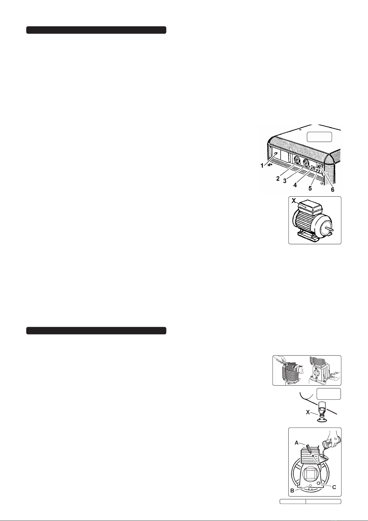
4.1. Ensure the ‘On/Off’ switch (fig.3.1) is in ‘Off’ position and the tank drain valve (fig.5) is closed.
4.2. Plug the lead into mains supply and start the compressor by pulling the ‘On/Off’ switch.
4.3. When starting the compressor for the first time, leave it running with air outlets (fig.3.5 & 6)
closed and regulator (fig.3.4) set to maximum pressure. Make sure that pressure in the tank
rises and that the compressor stops automatically when the max. pressure value allowed -
written on the plate and shown on the gauges (fig.3.2 & 3) - is achieved.
The compressor will now operate automatically. The pressure switch stops the motor when
the maximum tank pressure is reached and restarts it when pressure falls below the minimum
threshold - approx. 2 bar (29psi) less than the maximum pressure.
4.4. Stop the compressor by pushing the ‘On/Off’ switch (fig.3.1). The compressed air inside the
compressor head will flow out, making the restart easier and preventing the motor from being
damaged.
DO NOT, other than in an emergency,stop the compressor by switching off the mains socket, or
by pulling the plug out, as the pressure relief will not then occur and motor damage may result upon restart.
When the compressor runs correctly and is stopped correctly there will be:
(a) a whistle of compressed air when the motor stops and
(b) a protracted whistle (about 20-25 seconds) when the compressor starts with no pressure in the tank.
4.5. The compressor is equipped with an overload cut-out to protect the motor to gain access remove the back or
front panel of the compressor. The manual reset button (fig.4.X)
should not be operated until 3 minutes after cut-out, to allow the motor to cool. To restart, push
‘On/Off’ switch off, press the appropriate reset button and then pull ‘On/Off’ switch on. If, after restarting, the
compressor again automatically cuts out turn off and contact Service Agent.
4.6. The unregulated output from connector ‘A’ (fig.3.6) is intended to supply an external air tank. The pressure of this supply is shown on
gauge ‘A’ (fig.3.2).
4.7. The output from connector ‘B’ (fig.3.5) is regulated by the pressure regulator (fig.3.4) and is intended to supply air powered equipment.
The supply pressure is shown on gauge ‘B’ (fig.3.3). Pull and turn the regulator knob clockwise to increase pressure, anticlockwise to
reduce - push knob in to lock in required position. To determine the correct output pressure for any piece of equipment check the
manual supplied with it. When the compressor is not being used set the regulated pressure to zero so as to
avoid damaging the pressure regulator.
NOTE: a) If the motor does not cut in and out, but runs continuously when supplying an air appliance, the capacity of the compressor may be
insufficient for the appliance.
b) Should the pressure in the tank exceed the pressure switch maximum, a safety valve will activate. WARNING! For this reason
DO NOT tamper with, or adjust, the switch or safety valve.
4. OPERATION
In order to keep the compressor in good working condition, periodic maintenance is essential.
IMPORTANT! Failure to carry out maintenance tasks may invalidate the warranty on your compressor.
WARNING! Before performing any maintenance operation, switch off compressor, disconnect
from power supply and vent air from tank. Remove front and rear panels to provide access and
light.
5.1. After the first 50 working hours. Operations to be carried out:
a) Check that all bolts/nuts are tight, particularly those retaining the crank case and cylinder head.
b) Check oil level. Correct level is mid-way up sight glass (fig.6.C).
5.2. Daily. Operation to be carried out :
a) Drain condensation by opening the valve (fig.5.X) located under the tank.
5.3. Monthly (or more frequently, if the compressor operates in a very dusty atmosphere):
a) Check oil level and, if necessary, top up.
b) Remove the air filter element and clean by blowing through from the clean side, with an air line at low pressure.
Do not operate compressor without filter as foreign bodies or dust could damage the pump.
To access filter remove air hose from base of filter housing, undo wing nut located inside filter neck and
lower bottom section of housing.
c) Check belt tension.
d) Check for oil leaks.
e) Check safety valve. Pull ring to open valve, confirm air escapes. Release ring and confirm valve seals.
f) Check separator bowl and drain if necessary. Separator is behind and to the left of gauge ‘A’ (fig.3.2).
5.4. 3-monthly. Operation to be carried out a) Check tank for internal corrosion.
5.5. Every 500 hours. Operations to be carried out :
a) Change air filter element.
b) Check the automatic cut-out at max. pressure and the automatic cut-in at 2 bar below.
5. MAINTENANCE
fig. 3
fig. 4
fig. 5
fig. 6
Original Language Version SA4025/3.V3 Issue: 2 - 21/10/09
5.6. Every 1000 hours. Operations to be carried out :
a) Replace the lubricating oil. For oil specifications see 5.8.
Remove the oil breather (fig.6.A) and drain screw (fig.6.B), draining the oil into a container. Drain when the compressor is hot so that
oil drains rapidly and completely. Wash breather in kerosene, fuel oil or similar.
Replace screw ‘B’ and refill through the filler aperture. Do not overfill. Replace breather.
WARNING! Never mix different oils and do not use non-detergent/low quality oils as compressor may be damaged.
WARNING! Dispose of waste oil only in accordance with local authority requirements.
b) Check belt tension. A force of 3kg applied at the belt mid-point should give a deflection of approx. 10mm (fig.7). If adjustment is
required remember to maintain the alignment of the two pulleys (fig.7). Adjust by repositioning motor.
c) Check all tube fittings and electrical connections.
d) Inspect pressure tank inside and out for damage or corrosion.
5.7. Scheduled maintenance table
Maintenance
Operations Weekly 3 MonthlyMonthly 500hrs. 1000hrs.
Drain condensation
•
Check oil level •
Clean air filter
•
Check belt tension •
Check condition of belt
and pulleys
Check tube fittings and
electrical connections
Replace oil
Internal & external
inspection of tank
Check auto. cut-out
switch settings
Replace air filter
Check tank for internal
corrosion
Check for oil leaks
Drain separator
•
•
•
•
•
•
•
•
•
Fault Cause Remedy
Pressure drop in the tank Air leaks at connections
Run compressor to max. pressure, switch off.
Brush soap solution over connections and look for
bubbles. Tighten connections showing leaks.
If problem persists contact Authorised Service Agent.
Compressor noisy with metallic knock
Compressor speed fluctuates
Compressor does not reach max. pressure
Compressor does not stop at max. pressure
Compressor stops and does not restart
Pressure switch valve leaks when compressor is idle
Bearing or piston damage
Belt slipping
Filter clogged
Head gasket or valve fault
Pressure switch fault
Motor failure
Overload cut-out operated - motor overheating
Non-return valve seal defective
Contact Authorised Service Agent.
Adjust belt. See para. 5.6.b.
Replace filter element.
Contact Authorised Service Agent.
Press the reset button, see para. 4.5.
Empty the air tank, remove the non-return valve cap
‘A’ (fig.8) and clean. If necessary,
replace the seal ‘B’.
6. TROUBLE SHOOTING
5.8. Recommended oils
5.8.1 Recommended oil for compressors, suitable for room
5.8.2 temperatures ranging from +5°C to +25°C.
5.8.3 SEALEY CPO, or equivalent, SAE 40 compressor oil.
5.8.4 Room temperature below +5°C: SAE 20 compressor
oil.
5.8.5 Approximate oil capacity: 1.2 litres.
ALIGNMENT
A
B
fig. 8
fig. 7
NOTE: It is our policy to continually improve products and as such we reserve the right to alter data, specifications and component parts without prior notice.
IMPORTANT: No liability is accepted for incorrect use of this product.
WARRANTY: Guarantee is 12 months from purchase date, proof of which will be required for any claim.
INFORMATION: For a copy of our latest catalogue and promotions call us on 01284 757525 and leave your full name and address, including postcode.
01284 757500
01284 703534
sales@sealey.co.uk
Sole UK Distributor, Sealey Group,
Kempson Way, Suffolk Business Park,
Bury St. Edmunds, Suffolk,
IP32 7AR
www.sealey.co.uk
Web
email
Original Language Version SA4025/3.V3 Issue: 2 - 21/10/09

Other Sealey Air Compressor manuals

Sealey RE229.V4 User manual

Sealey

Sealey RE229.V4 User manual

Sealey SAC5020E.V2 User manual

Sealey

Sealey SAC5020E.V2 User manual

Sealey SAC1103B User manual

Sealey

Sealey SAC1103B User manual

Sealey SAC10030VE.V2 User manual

Sealey

Sealey SAC10030VE.V2 User manual

Sealey SAC1503B User manual

Sealey

Sealey SAC1503B User manual

Sealey SA2250/2.V2 User manual

Sealey

Sealey SA2250/2.V2 User manual

Sealey SAC0502B.V2 User manual

Sealey

Sealey SAC0502B.V2 User manual

Sealey AirPower SAC5020E.V3 User manual

Sealey

Sealey AirPower SAC5020E.V3 User manual

Sealey MAC23250 User manual

Sealey

Sealey MAC23250 User manual

Sealey AK3845.V2 User manual

Sealey

Sealey AK3845.V2 User manual

Sealey SAC9030VE User manual

Sealey

Sealey SAC9030VE User manual

Sealey MAC2300 User manual

Sealey

Sealey MAC2300 User manual

Sealey MS163 User manual

Sealey

Sealey MS163 User manual

Sealey Power PRODUCTS SA5055 User manual

Sealey

Sealey Power PRODUCTS SA5055 User manual

Sealey SAC2203BLN.V2 User manual

Sealey

Sealey SAC2203BLN.V2 User manual

Sealey SAC42055B.V2 User manual

Sealey

Sealey SAC42055B.V2 User manual

Sealey RE229 User manual

Sealey

Sealey RE229 User manual

Sealey MAC03 User manual

Sealey

Sealey MAC03 User manual

Sealey SA1015/3 User manual

Sealey

Sealey SA1015/3 User manual

Sealey SAC32775B User manual

Sealey

Sealey SAC32775B User manual

Sealey SA2110/3 User manual

Sealey

Sealey SA2110/3 User manual

Sealey MAC23250 User manual

Sealey

Sealey MAC23250 User manual

Sealey SA200T.V2 User manual

Sealey

Sealey SA200T.V2 User manual

Sealey SSQC0903P User manual

Sealey

Sealey SSQC0903P User manual

Popular Air Compressor manuals by other brands

Hitachi NEXT Series instruction manual

Hitachi

Hitachi NEXT Series instruction manual

Keiser 1031 Replacement guide

Keiser

Keiser 1031 Replacement guide

Speedaire 5Z598C Operating instructions and parts manual

Speedaire

Speedaire 5Z598C Operating instructions and parts manual

GEA pluscom Bock EX-HG12P Assembly instructions

GEA

GEA pluscom Bock EX-HG12P Assembly instructions

Bitzer CSH Series manual

Bitzer

Bitzer CSH Series manual

Airmec TT 22 MT 2011 Maintenance and operation handbook

Airmec

Airmec TT 22 MT 2011 Maintenance and operation handbook

Oshkosh Corporation IMT CAS80R Installation, Operation, Maintenance & Parts Manual

Oshkosh Corporation

Oshkosh Corporation IMT CAS80R Installation, Operation, Maintenance & Parts Manual

Atlas Copco GA 11+ Instruction book

Atlas Copco

Atlas Copco GA 11+ Instruction book

Husky Y1000 Operator's manual

Husky

Husky Y1000 Operator's manual

Hyundai AirPower user guide

Hyundai

Hyundai AirPower user guide

Alsafix ALAIR 20/255 User manual and  spare parts list

Alsafix

Alsafix ALAIR 20/255 User manual and spare parts list

Scheppach GK240of Translation of original instruction manual

Scheppach

Scheppach GK240of Translation of original instruction manual

California Air Tools 10010DC owner's manual

California Air Tools

California Air Tools 10010DC owner's manual

Iwata IS-50 Silver Jet Assembly instructions

Iwata

Iwata IS-50 Silver Jet Assembly instructions

Powermate 200-2275 Operator's manual

Powermate

Powermate 200-2275 Operator's manual

Powermate 200-2454 parts manual

Powermate

Powermate 200-2454 parts manual

Ingersoll-Rand IRN 20HP Operation and maintenance manual

Ingersoll-Rand

Ingersoll-Rand IRN 20HP Operation and maintenance manual

Kenmore 8424 operating instructions

Kenmore

Kenmore 8424 operating instructions

manuals.online logo
manuals.online logoBrands
  • About & Mission
  • Contact us
  • Privacy Policy
  • Terms and Conditions

Copyright 2025 Manuals.Online. All Rights Reserved.