Thank you for purchasing a Sealey Product. Manufactured to a
high standard this product will, if used according to these
instructions and properly maintained, give you years of trouble
free performance.
IMPORTANT: PLEASE READ THESE INSTRUCTIONS CAREFULLY. NOTE THE SAFE OPERATIONAL
REQUIREMENTS, WARNINGS AND CAUTIONS. USE THIS PRODUCT CORRECTLY AND WITH CARE FOR THE
PURPOSE FOR WHICH IT IS INTENDED. FAILURE TO DO SO MAY CAUSE DAMAGE AND/OR PERSONAL
INJURY AND WILL INVALIDATE THE WARRANTY. PLEASE KEEP INSTRUCTIONS SAFE FOR FUTURE USE.
1. SAFETY INSTRUCTIONS
INSTRUCTIONS FOR:
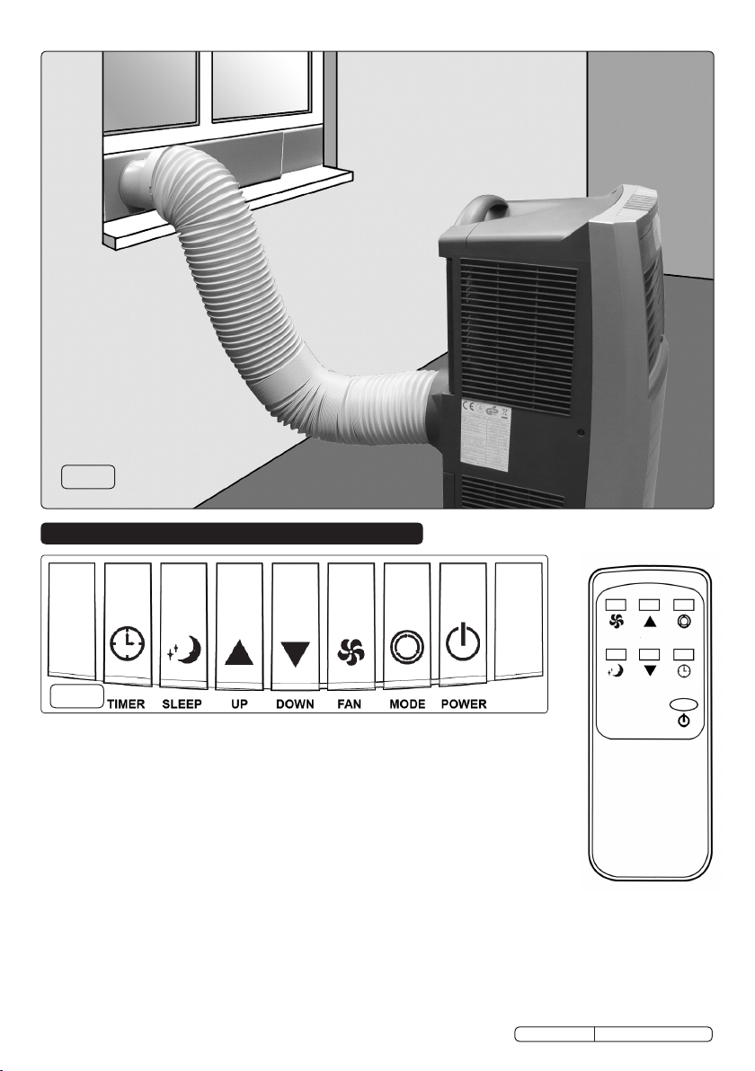
AIR CONDITIONER,
DEHUMIDIFIER, HEATER UNIT
MODEL No: SAC9000.V2
1.1. ELECTRICAL SAFETY
WARNING! It is the responsibility of the owner and the operator to read, understand and comply with the following:
You must check all electrical products, before use, to ensure that they are safe. You must inspect power cables, plugs,
sockets and any other connectors for wear or damage. You must ensure that the risk of electric shock is minimised by
the installation of appropriate safety devices. A Residual Current Circuit Breaker (RCCB) should be incorporated in the
main distribution board. We also recommend that a Residual Current Device (RCD) is used. It is particularly important
to use an RCD with portable products that are plugged into a supply which is not protected by an RCCB. If in any doubt
consult a qualified electrician. You may obtain a Residual Current Device by contacting your Sealey dealer.
You must also read and understand the following instructions concerning electrical safety.
1.1.1. The Electricity at Work Act 1989 requires that all portable electrical appliances, if used on business
premises, are tested by a qualified electrician, using a Portable Appliance Tester (PAT), at least once a year.
1.1.2. The Health & Safety at Work Act 1974 makes owners of electrical appliances responsible for the safe
condition of those appliances and the safety of the appliance operators. If in any doubt about electrical
safety, contact a qualified electrician.
1.1.3. Ensure that the insulation on all cables and on the appliance is safe before connecting it to the power supply.
See 1.1.1. and 1.1.2. and use a Portable Appliance Tester.
1.1.4. Ensure that cables are always protected against short circuit and overload.
1.1.5. Regularly inspect power supply cables and plugs for wear or damage and check all connections to ensure that
none is loose
1.1.6. Important: Ensure that the voltage marked on the appliance matches the
power supply to be used and that the plug is fitted with the correct fuse -
see fuse rating at right.
1.1.7. DO NOT pull or carry the appliance by the power cable.
1.1.8. DO NOT pull the plug from the socket by the cable.
1.1.9. DO NOT use worn or damaged cables, plugs or connectors. Immediately
have any faulty item repaired or replaced by a qualified electrician. When a
BS 1363/A UK 3 pin plug is damaged, cut the cable just above the plug
and dispose of the plug safely.
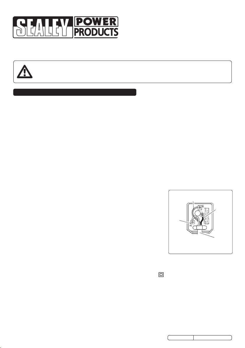
Fit a new plug according to the following instructions (UK only).
a) Connect the GREEN/YELLOW earth wire to the earth terminal ‘E’.
b) Connect the BROWN live wire to the live terminal ‘L’.
c) Connect the BLUE neutral wire to t he neutral terminal ‘N’.
d) After wiring, check that there are no bare wires, that all wires have been
correctly connected, that the cable outer insulation extends beyond the cable restraint and that the
restraint is tight.
Double insulated products, which are always marked with this symbol , are fitted with live (brown) and
neutral (blue) wires only. To rewire, connect the wires as indicated above - DO NOT connect either wire to the
earth terminal.
1.1.10. Products which require more than 13 amps are supplied without a plug. In this case you must contact a
qualified electrician to ensure that a suitably rated supply is available. We recommend that you discuss the
installation of an industrial round pin plug and socket with your electrician.
1.1.11. If an extension reel is used it should be fully unwound before connection. A reel with an RCD fitted is
preferred since any appliance plugged into it will be protected. The cable core section is important and should
be at least 1.5mm², but to be absolutely sure that the capacity of the reel is suitable for this product and for
others which may be used in the other output sockets, we recommend the use of 2.5mm² section cable.
FUSE RATING 13 AMP
Blue
Neutral
Wire
Yellow & Green
Earth Wire
Cable
Restraint
Brown
Live
Wire
Original Language Version SAC9000.V2 Issue No.1 19/01/10


 null")