Sealey SAC7000.V2 User manual

7,000, 9000 BTU/HR PORTABLE AIR CONDITIONER/
DEHUMIDIFIER/AIR COOLER, WINDOW SEALING KIT
MODEL NO: SAC7000.V2, SAC9002.V3, SACWK1
Thank you for purchasing a Sealey product. Manufactured to a high standard, this product will, if used according to these
instructions, and properly maintained, give you years of trouble free performance.
IMPORTANT: PLEASE READ THESE INSTRUCTIONS CAREFULLY. NOTE THE SAFE OPERATIONAL REQUIREMENTS, WARNINGS & CAUTIONS. USE
THE PRODUCT CORRECTLY AND WITH CARE FOR THE PURPOSE FOR WHICH IT IS INTENDED. FAILURE TO DO SO MAY CAUSE DAMAGE AND/OR
PERSONAL INJURYAND WILL INVALIDATE THE WARRANTY. KEEP THESE INSTRUCTIONS SAFE FOR FUTURE USE.
1. SAFETY
1.1. ELECTRICAL SAFETY
WARNING! It is the responsibility of the owner and the operator to read, understand and comply with the following:
You must check all electrical products, before use, to ensure that they are safe. You must inspect power cables, plugs, sockets
and any other connectors for wear or damage. You must ensure that the risk of electric shock is minimised by the installation of
appropriate safety devices. A Residual Current Circuit Breaker (RCCB) should be incorporated in the main distribution board. You
must also read and understand the following instructions concerning electrical safety.
9Ensure that cables are always protected against short circuit and overload.
9Regularly inspect power supply cables and plugs for wear or damage and check all connections
to ensure that none are loose.
9Ensure that the voltage marked on the appliance matches the power supply to be
usedandthattheplugisttedwiththecorrectfuse-seefuseratingatright.
8DO NOT use worn or damaged cables, plugs or connectors. Have any faulty item repaired or
replaced immediately by a competent electrician.
9It is recommended that this device is wired directly to a fused isolator switch. If, however, a plug
istted,thefollowingapplies:
9Fit a new plug according to the following instructions (UK only).
a) Connect the GREEN/YELLOW earth wire to the earth terminal ‘E’.
b) Connect the BROWN live wire to the live terminal ‘L’.
c) Connect the BLUE neutral wire to the neutral terminal ‘N’.
d) After wiring, check that there are no bare wires, that all wires have been correctly connected,
that the cable restraint is tight.
1.2. GENERAL SAFETY
9Check that the unit is in sound condition and good working order. Take immediate action to repair or replace damaged parts.
Use recommended parts only. Unauthorised parts may be dangerous and will invalidate the warranty.
NOTE: The appliance is designed for use with propane gas R290 only as it’s designated refrigerant.
WARNING: The refrigerant loop is sealed. Servicing should only be carried out by a qualified technician.
8DO NOT discharge the refrigerant into the atmosphere.
NOTE: Only install or operate in a room with a floor area exceeding 7m2.
8DO NOT attempt any repairs or maintenance unless suitably qualified.
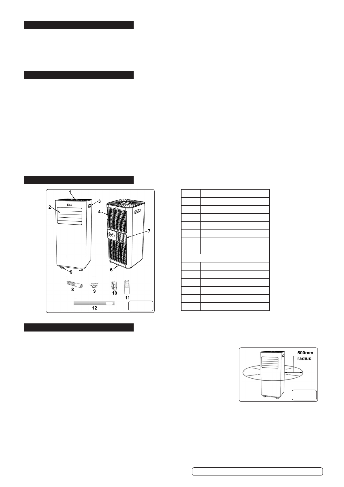
8DO NOT stand or place any object closer than 500mm (20 inches) from the unit.
8DO NOT obstruct the air intakes or outlets of the unit.
8DO NOT cover with items of clothing. DO NOT sit or climb onto the unit.
8DO NOT place any object into the outlets.
8DO NOT operate the unit when you are tired or under the influence of alcohol, drugs or intoxicating medication.
8DO NOT switch the unit off by disconnecting it from the mains. ALWAYS switch it off using the Power button.
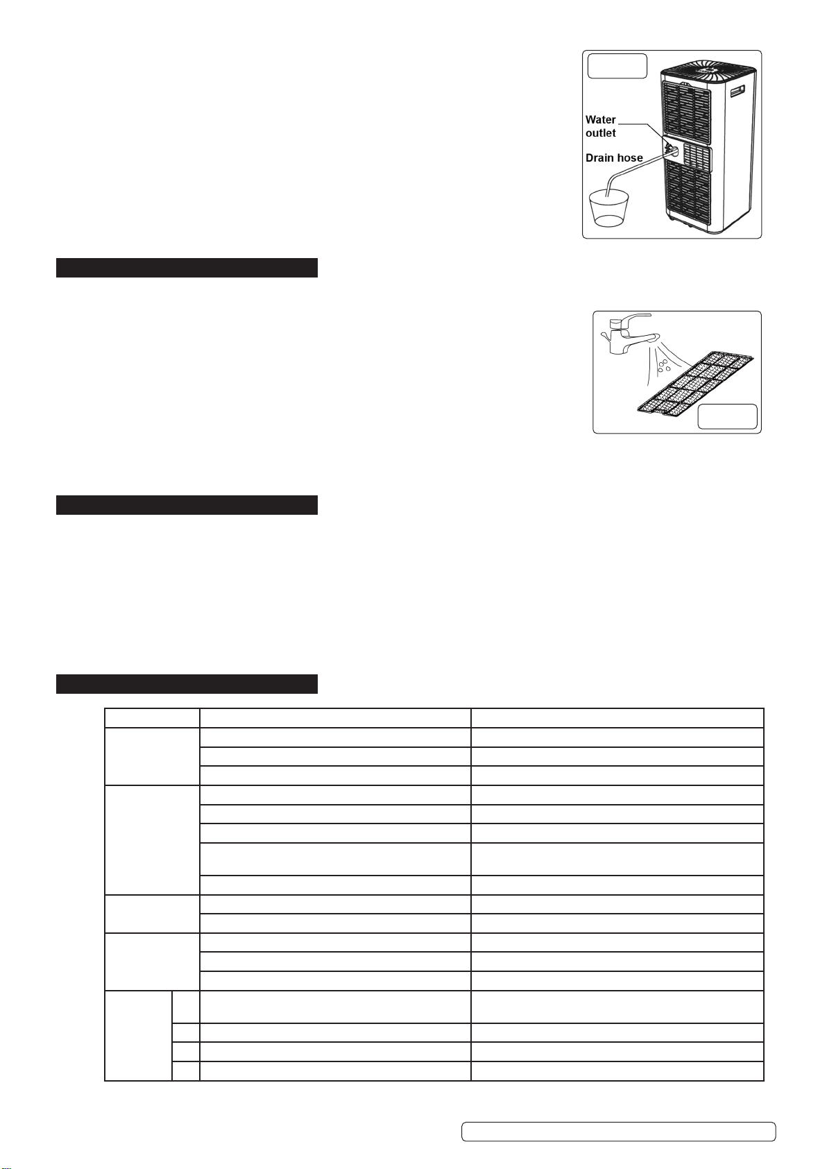
8DO NOT remove the float lever from the water collection tank.
8DO NOT connect or disconnect the plug from the mains or use the unit with wet hands. Keep the unit dry.
8DO NOT use the unit outside.
8DO NOT install or operate this air conditioner in a bathroom or other wet environments.
9To prevent water from freezing, DO NOT use the unit at ambient temperatures below 0°C.
9Always discard the water from the collection tank, DO NOT use it for any other purpose.
9Place the unit on a level and stable surface.
9If the appliance is tipped at an angle greater than 45°, leave it to stand for at least 24 hours before use.
9 Ensurethatheatingappliancesarenotexposedtotheowofairfromtheunit.
9 Beforeattemptingtomovetheunit,emptythecontentsofthewatertank.Usecarryinghandle(g1.3)whenmovingunit.
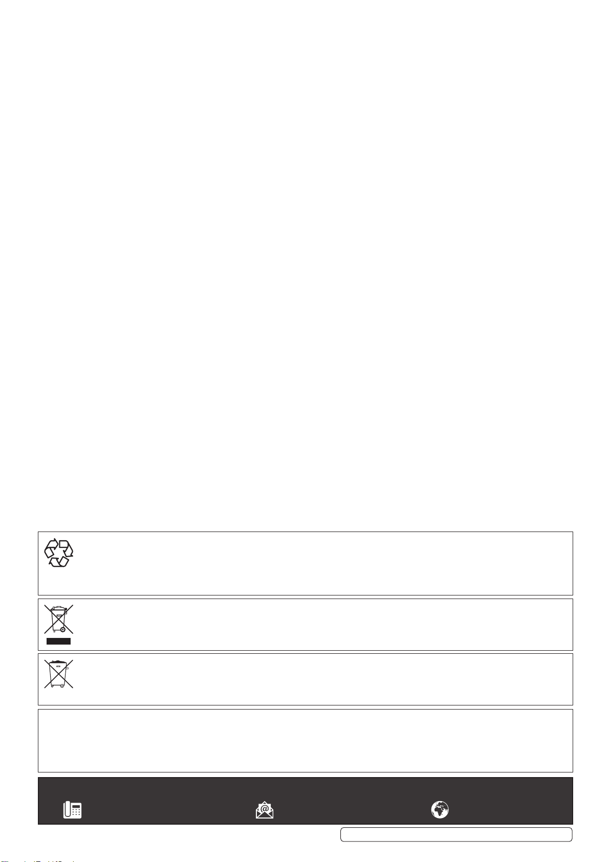
9 Switchoanddisconnectunitfromthemainsbeforeattemptinganycleaningorothermaintenancework.
9 Ensurethattheunitisturnedocorrectlywhennotinuse,andstoredinasafe,dryarea,outofreachofchildren.
NOTE: This appliance can be used by children aged from 8 years and above and persons with reduced physical, sensory or
mental capabilities or lack of experience and knowledge if they have been given supervision or instruction concerning use of
the appliance in a safe way and understand the hazards involved. Children shall not play with the appliance. Cleaning and user
maintenance shall not be made by children without supervision.
Recommended fuse rating
13 Amp
SAC7000.V2,SCS9002.V3,SACWK1Issue105/01/23
Original Language Version© Jack Sealey Limited
Refer to
instructions Do not cover Caution:
riskofre
Indoor use
only

2. INTRODUCTION
3-in-1highcapacity,compact,portableairconditioner,aircoolingwithventilationanddehumidifyingfunctions.Thermostaticallycontrolled
withbuilt-in24hrtimerandsleepmode.Soft-touchcontrolpanelwithLEDdigitaldisplayandremotecontrol.Self-evaporatingsystemreuses
themoistureitcollectsfromtheairtohelpwiththecoolingprocessallowsbettereciency,lowmaintenanceandpowerfulcooling.Water-
fullindicatorwithauto-shut-o.Suppliedwithextendableexhaustductingwithwindowkitsforventilation.Dehumidifyingfunctioncapableof
removingupto14.6L/dayandincludescontinuousdrainhose.Eco-FriendlyR290refrigerant.Airconditioningtemperaturerange16-32°C.
Washablelter.Auto-defrostfunctionatlowambienttemperature.Mountedoncastorwheelsformanoeuvrability.
3. SPECIFICATION
Model No.: ........................................................ SAC7000.V2
Cooling Capacity:..................................................7000Btu/hr
Discharge Side Pressure: ..........................................3.2MPa
Energy Rating:....................................................A(EER:2.6)
IP Rating:.......................................................................IPX1
Mass of Refrigerant:.......................................................120g
MaximumAirow:.....................................................290m³/hr
Maximum Exhaust Hose Length: ...................................1.5m
Maximum Water Extraction Rate:........................... 14.6L/day
Noise Level:.............................................................. 65db(A)
Power:...........................................................................780W
Rated Capacity: ..........................................................2050W
Refrigerant:................................................................... R290
Suction Side Pressure:...............................................0.7MPa
Supply:................................................................ 230V~50Hz
4. CONTENTS
5. INSTALLATION
Unpack the product and check contents. Should there be any damaged or missing parts contact your supplier immediately.
5.1. LOCATION
5.1.1. Placetheapplianceonarm,levelsurface.
5.1.2. Ensurethatthereisaclearareaofatleast500mmaroundtheappliance(g.2)toallowfor
adequate air circulation.
8DO NOT operate the appliance in close proximity to walls, curtains or other objects that may
block the air inlet or outlet.
WARNING! DO NOT locate the appliance where it is subject to:
Heat sources such as radiators, ovens or similar
Direct sunlight
Mechanical vibration or shock
Excessive dust
Lack of ventilation i.e., inside a cabinet or bookcase
Uneven surfaces
5.2. ASSEMBLE THE EXHAUST HOSE
WARNING! The air conditioning unit must be vented to outside. This ensures that any heat and moisture is removed from the
designated room space.
5.2.1. Screwtthehoseconnectortooneendoftheexhausthose(g.3).
5.2.2. Screwtthewindowkitadaptertotheotherendoftheexhausthose(g.4).
Original Language Version
© Jack Sealey Limited
ITEM DESCRIPTION
1Control panel
2Air outlet with adjustable louvre
3Handle
4Air inlet and filter
5Castor wheel
6Drainage hole
7Air exhaust
ACCESSORIES
8Exhaust hose
9Hose connector
10 Window kit adaptor
11 Remote control
12 Window kit
13 Drain hose (not shown)
g.1
g.2
Model No.: ........................................................ SAC9000.V3
Cooling Capacity:..................................................9000Btu/hr
Discharge Side Pressure: ..........................................3.2MPa
Energy Rating:....................................................A(EER:2.6)
IP Rating:.......................................................................IPX1
Mass of Refrigerant:.......................................................170g
MaximumAirow:.....................................................330m³/hr
Maximum Exhaust Hose Length: ...................................1.5m
Maximum Water Extraction Rate:.............................. 25L/day
Noise Level:.............................................................. 65db(A)
Power:.........................................................................1005W
Rated Capacity: ..........................................................2600W
Refrigerant:................................................................... R290
Suction Side Pressure:...............................................0.7MPa
Supply:................................................................ 230V~50Hz
SAC7000.V2,SCS9002.V3,SACWK1Issue105/01/23

Original Language Version
© Jack Sealey Limited
5.3. WINDOW KIT ASSEMBLY
5.3.1. Locatewindowkitlockingbracket’sthreadedshaftthroughholeinwindowkitpartB(g.5).
5.3.2. Attachwasherandwingnuttothreadedshaft(g.5).
5.3.3. SlidewindowkitpartAintopartB(g6)andlocatelockingbracketplateintocentralslotonpartA(g.5).
5.3.4. Extendtheadjustablewindowkittosuitthesizeofthewindowandtightenthewingnut(g.5)tolock.
5.3.5. Attachexhausthoseassembly,seesection5.2,towindowkitpartB(g.6).
5.4. ATTACH WINDOW KIT ASSEMBLY SEE ALSO SECTION 10 FOR ALTERNATIVE WINDOW KIT INCLUDED WITH THE MODEL’S
5.4.1. Openthewindowandplacethewindowkitintoposition,thenclosethewindowontothewindowkit(g.7).
NOTE: To obtain maximum efficiency it is recommended that any gaps between the window kit and the sides of the window are
sealed.
5.4.2. Attachthehoseconnectoronthehoseassemblytotheexhaustoutlet(g.1#7)byslidingtheithorizontallyintoposition(g.8).
5.4.3. Placetheapplianceneartoasuitableelectricalpoweroutletandadjusttheexibleexhausthosetosuit,avoidinganysharpbends
tothehose(g.9).
5.4.4. Adjustthelouvrepanel(g.1#2)tosuit(g.9).
6. OPERATION
6.1. CONTROL PANEL AND DISPLAY
g.3 g.4
g.5
g.6
g.7
g.8 g.9
g.10
1LOCK Press to turn ON or OFF the child lock function
2 MODE Press to switch operation mode between cooling,
dehumidifier and fan
3UP Increasetemperature(16ºC~32ºC)ortimersetting
4 POWER Press to turn the unit ON or OFF
5 DOWN Decreasing the temperature or timer setting
6SPEED Press to switch the fan speed between HIGH or LOW
7 TIMER Sets a time for the unit to automatically START or STOP
8FAN SPEED
INDICATOR Displays HIGH or LOW fan speed
9 DIGITAL
DISPLAY Displays timer setting and room temperature
10 MODE
INDICATOR Mode display between Cooling, Dehumidifying and Fan
6.1.1. Thedisplayonthefrontfaceoftheunitwillonlylightwhentheunitisincoolingmode.
SAC7000.V2,SCS9002.V3,SACWK1Issue105/01/23

Original Language Version
© Jack Sealey Limited
6.2. SETTINGS
6.2.1. START UP AND SHUTDOWN
6.2.1.1. PressPOWERtoturntheunitON(g.10#4).
6.2.1.2. PressMODEbuttontoselectthedesiredoperationmode(g.10#2).
6.2.1.3. PressPOWERagaintoturntheunitOFF(g.10#4).
6.2.2. OPERATION MODE
The unit has four operation modes: Cool, dehumidifier, fan and sleep.
6.2.3. COOLING A ROOM
6.2.3.1. Select the COOL mode to lower the temperature in a room.
6.2.3.2. PressMODEbutton(g.10#2)untiltheCOOLindicatorilluminates(g.10#10).
6.2.3.3. PresstheUPorDOWNbutton(g.10#3#5)toadjustthetemperaturetothedesiredlevel.Thetemperaturewillbedisplayedon
thescreen(g.10#9).Thetemperaturecanbesetbetween16ºCto32ºC.
6.2.3.4. PresstheSpeedbutton(g.10#6)Untilthedesiredfanspeedindicatorilluminates(g.10#8).
NOTE:Thehorizontalairflowdirectioniscontrolledbyadjustingtheairoutletlouvres(fig.1#2).
WARNING! The air conditioner function will stop if the room temperature is lower than the selected temperature.
6.2.4. VENTILATE THE ROOM
6.2.4.1. PresstheMODEbutton(g.10#2)untiltheFANindicatorilluminates(g.10#10).
NOTE: In ventilation mode the room air is circulated NOT cooled.
6.2.4.2. PresstheSpeedbutton(g.10#6)Untilthedesiredfanspeedindicatorilluminates(g.10#10).
6.2.5. DRYING THE ROOM
6.2.5.1. PresstheMODEbuttononthecontrolpanel(g.10#2)untiltheDRYindicatorilluminates(g.10#10),orpresstheDRYbuttonon
theremotecontrol(g.11).
6.2.5.2. Connectthedrainhose(fig.1#13)Tothedrainoutletatthebottomoftheunit(fig.1#6).Seesection6.5.
NOTE: In this mode the fan speed is set to low level and cannot be changed.
6.2.6. SLEEP MODE
WARNING!ThisfunctioncanonlybeactivatedbyusingtheSLEEPbuttonontheremotecontrol(g.11).
To activate the sleep mode the unit must be in the COOL mode.
6.2.6.1. ToactivateCOOLmodepresstheCOOLbuttonontheremotecontrolandthenpresstheSLEEP(g.11).
NOTE:After1hourthepre-settemperatureisincreasedby1ºCandincreasedagainby1ºCthefollowing
hour.
6.2.7. TIMER SETTING (1 to 24 hours)
6.2.7.1. The TIMER has two ways of operation and can be activated by either the button on the control panel
(g.10#7)orbytheTIMERbuttonontheremotecontrol(g.11).
6.3. AUTOMATIC DEFROST
During use if operating at low room temperatures frost may build up at the evaporator. The POWER indicator will start to blink and
the unit will automatically begin to defrost.
The defrost control sequence is as follows:
A. If operating the unit in either the cooling or drying mode, the ambient temperature sensor senses that the evaporator coil
temperatureisbelow-1ºCthecompressorwillstop.Itwillrestartagain,intheCOOLmode,after10minutesorwhenthecoil
reachesthetemperatureof7ºC.
B.Ifoperatingtheunitinthedryingmode,thecoiltemperaturesensorsensesthatthetemperatureoftheevaporatorisbelow40ºC
andthedierentialtemperaturebetweenthecoiltemperatureandtheambientroomtemperatureisbelow19ºCandthecompressor
hasbeeninoperationfortwentyminutestheunitwillstartdefrostingforveminutesandthePOWERindicatorwillbeginto
blink.
6.4. OVERLOAD PROTECTION
If there is a loss of power, to protect the compressor, there is a three minute delay until the
compressor will restart.
6.5. MANUAL DRAINAGE
NOTE: When the unit is full of water it will automatically shut off.
6.5.1. Switchotheunitandremovetheelectricalplugfromit’spowersource.
6.5.2. With care move the unit to suitable location to enable a container to be located below the
bottomdrainagehole(g.1#6).
6.5.3. Withthecontainerinplaceremovethedrainplug(g.12).
WARNING!Thewaterwillowoutinstantlyfromthedrainagehole.
6.5.4. When the unit has completely drained replace the drain plug back fully into the drainage hole.
NOTE: To assist with drainage the unit can be slightly tilted backwards to allow the drain plug to
bere-insertedifthecontainerbecomesfull.
6.5.5. Replacetheelectricplugintothepowersourceandre-starttheapplianceinthedesiredmode.
WARNING!Ensurethatthedrainplugisfullyinserted,otherwisethecondensatewaterwillow
outontotheoor.
g.12
g.11
SAC7000.V2,SCS9002.V3,SACWK1Issue105/01/23

6.6. CONTINUOUS DRAINAGE
Toprovideamoreefficientperformancetheself-evaporatingsystemusesthecollectedwater
to cool the condenser coils.
It is recommended not to use the continuous drain method in the cooling mode.
The condensate water evaporates at the condenser and is expelled through the exhaust hose.
6.6.1. Switchotheunitandremovetheelectricalplugfromit’spowersource.
6.6.2. Releasethecoverfromthewateroutletopening(g.13).
6.6.3. Withcarepushtoneendofthedrainhoseontothewateroutlet(g.13).
6.6.4. Securely place the other end of the drain hose over a suitably sized container or drain.
WARNING! Ensure that the drain hose is straight and free from any kinks and at an inclination
angledownwardsofnotmorethan20º.
8DO NOT allow the open end of the drain hose to be submerged into the water. This may cause
an air lock in the hose.
NOTE: The condensate water will automatically flow into the container or drain.
7. MAINTENANCE
NOTE: Maintenance, service and repair must be carried out by qualified person. Contact your Sealey stockist for details.
7.1. CLEANING
7.1.1. Switchotheunitandremovetheelectricalplugfromit’spowersource.
7.1.2. Clean the unit with soft damp cloth.
8DO NOT use solvents.
7.2. CLEANING THE AIR FILTER
The air filter requires regular cleaning. A restricted airflow will reduce the efficiency of the system.
It is recommended that air filter is cleaned every two weeks.
8DO NOToperatetheunitwithoutanairlter.
7.2.1. Switchotheunitandremovetheelectricalplugfromit’spowersource.
7.2.2. Removetheltermeshfromtheunit(g.1#4).
7.2.3. Useahouseholdvacuumtoremoveanydustfromthelter.
7.2.4. Turnthelteroverandrinsethelterunderrunningwater(g.14).
7.2.5. Allowtheltertodrybeforereinstalling.
8. STORAGE
8.1. Turnontheunitandselectthelowwindventilationmode.Seesection6.2.4.
8.1.1. Leave in this condition until the drainage pipe becomes dry.
NOTE: This will help prevent mildew.
8.2. Switchotheunitandremovetheelectricalplugfromit’spowersource.
8.3. Remove the window kit, exhaust hose and drain hose.
8.4. Draintheremainingwaterfromtheunit.Seesection6.5.
8.5. Replace any drainage plugs.
8.6. Cleanthelter.Seesection7.2.
8.7. Remove the batteries from the remote control.
8.8. Store the unit and accessories in it’s original packaging, in safe dry childproof location.
9. TROUBLESHOOTING
Original Language Version
© Jack Sealey Limited
g.13
g.14
SYMPTOM POSSIBLE CAUSE REMEDY
The unit is not
working No power Connect to power source and turn the unit ON
Full water indicator is illuminated Drain the water
Low room temperature Change the set temperature
The unit works
with reduced
capacity
Dirty air filter Clean the air filter as required
Air ducts are blocked Clearobstacles.Re-positionunitintoclearspace
Doors or windows open Close the doors and windows
Incorrect mode and temperature selected Select correct mode and temperature to suit desired
application
Detached exhaust hose Securely reattach exhaust hose
Water leakage Spillage when moving the unit Empty the water tank before moving the unit
The drain hose is kinked or bent Straighten the drain hose
Excessive noise The unit is on an uneven surface Place the unit onto a flat horizontal surface
Loose, vibrating parts Checkforloosepartsandre-tighten
Water flowing sound Normal sound of refrigerant flowing
Error
codes E0 Communication faults between main PCB and
display PCB Contact Sealey service centre
E1 Ambient temperature sensor fail Contact Sealey service centre
E2 Coil temperate sensor failures Contact Sealey service centre
Ft Condensate water high level alarm Drain the water
SAC7000.V2,SCS9002.V3,SACWK1Issue105/01/23

WINDOW SEALING KIT FOR AIR CONDITIONER DUCTING
MODEL NO: SACWK1
10. SAFETY
8DO NOT cover the unit with this material, and do not obstruct the air inlet and outlet grilles of the machine with items such as
clothing,soft furnishings, furniture, bedding etc.
8DO NOT use the material for any purpose other than that for which it is designed.
8DO NOT use in bathroom or shower room.
8DO NOT allow children to use, when not in use,store in a safe, cool, dry, childproof area.
NOTE: This material is not intended for use by persons (including children) with reduced physical, sensory or mental capabilities or
lack of experience and knowledge, unless they have been given supervision or instruction concerning the use of the appliance by a
person responsible for their safety. Children should be supervised to ensure that they do not play with this material.
11. INTRODUCTION
Suitableforalltypesofhingedwindowsincludingskylightsupto300cmtotalperimeter.Easytoinstallusingthesuppliedrollofself-
adhesive hook & loop tape. Double zip makes positioning the ducting at any height easy. Saves energy by making the air conditioner
ordryermoreeective.
12. CONTENTS
Window seal
Velcro tape
13. INSTRUCTIONS
13.1. CLEANING
Clean the window and window frame, making them free from grease and dust.
13.2. CUTTING THE VELCRO TAPE TO SIZE
CuttheVelcrotapetosize,usingapairofscissors.Markthemiddle(M)ofthewindowseal(Fig.1).Markthemiddleofthewindow
frameandthecasement(Fig.2-4)(Figure2showsanopenwindow,Figure3atiltedwindowandFigure4anopenskylight).
13.3. VELCRO TAPE TO THE WINDOW FRAME
Adhere the Velcro tape to the window frame around the window. Then adhere the Velcro tape fully around the window. Stick the Velcro
tapetothefrontside(inmostcases1cmwide)ofthecasementortotheinnersurfaceofthecasement(wherethewindowhandleis
attached).
CAUTION: DO NOT adhere the Velcro tape on the window.
13.4. SEALING WINDOW TO WINDOW FRAME
Adhere the narrow side of the window seal to the Velcro tape on the window frame. Work from the centre and fully adhere the
narrow side all the way around. First fasten side A, then side B, starting in the middle and working all the way to the left and right.
IMPORTANT! When fastening, pointA must be exactly opposite point B.
13.5. SEALING THE WINDOW
Leave the window ajar and adhere the wide side of the window seal to the Velcro tape of the window.
CAUTION:Leavesucientspace,sothatthewindowsealwillnotgetjammed
13.6. OPENING THE WINDOW SEAL
Open the zip of the window seal approximately 50 cm. Open the zip preferably at the positions marked with “S” and attach the exhaust
air hose.
13.7. ATTACHING THE AIR DISCHARGE
Insert the air discharge hose of the air conditioning system through the hole in the window seal and close the zip until the air discharge
hose is properly secured
13.8. CLOSING THE WINDOW
If you want to close your window, simply detach the cloth from the Velcro tape. When closing the window take care that the seal is not
jammed between the casement and window frame.
NOTE: This window seal ensures that the room remains cool for a longer period of time and keeps insects and mosquitoes out.
Original Language Version© Jack Sealey Limited
Window seal with zip
Velcro tape
SAC7000.V2,SCS9002.V3,SACWK1Issue105/01/23

Original Language Version© Jack Sealey Limited
M= MIDDLE
POLYESTER
MATERIAL
g.1
g.2
OPEN WINDOW
g.3
TILTED WINDOW g.4
OPEN SKYLIGHT
g.5 g.6
13.9. Theinstalleditemwillresembleg.5andg.6.
SAC7000.V2,SCS9002.V3,SACWK1Issue105/01/23

Original Language Version
© Jack Sealey Limited
ENVIRONMENT PROTECTION
Recycle unwanted materials instead of disposing of them as waste. All tools, accessories and packaging should be sorted, taken to
a recycling centre and disposed of in a manner which is compatible with the environment. When the product becomes completely
unserviceable and requires disposal, drain any fluids (if applicable) into approved containers and dispose of the product and fluids
according to local regulations.
WEEE REGULATIONS
Dispose of this product at the end of its working life in compliance with the EU Directive on Waste Electrical and Electronic Equipment
(WEEE). When the product is no longer required, it must be disposed of in an environmentally protective way. Contact your local solid
waste authority for recycling information.
BATTERY REMOVAL: REMOVE BATTERY FROM REMOTE
Under the Waste Batteries and Accumulators Regulations 2009, Jack Sealey Ltd are required to inform potential purchasers of products
containing batteries (as defined within these regulations), that they are registered with Valpak’s registered compliance scheme. Jack
Sealey Ltd Batteries Producer Registration Number (BPRN) is BPRN00705.
Note: It is our policy to continually improve products and as such we reserve the right to alter data, specifications and component parts without prior
notice. Please note that other versions of this product are available. If you require documentation for alternative versions, please email or call
ourtechnicalteamontechnical@sealey.co.ukor01284757505.
Important: No Liability is accepted for incorrect use of this product.
Warranty:Guaranteeis12monthsfrompurchasedate,proofofwhichisrequiredforanyclaim.
Sealey Group, Kempson Way, Suffolk Business Park, Bury St Edmunds, Suffolk. IP32 7AR
01284 757500 sales@sealey.co.uk www.sealey.co.uk
SAC7000.V2,SCS9002.V3,SACWK1Issue105/01/23
This manual suits for next models
2
Table of contents
Other Sealey Air Conditioner manuals

Sealey
Sealey SAC12000.V3 User manual

Sealey
Sealey SAC9002 User manual

Sealey
Sealey SAC9002.V2 User manual

Sealey
Sealey sac9000.V3 User manual

Sealey
Sealey SAC12000 User manual

Sealey
Sealey SAC125 User manual

Sealey
Sealey SAC41.V3 User manual

Sealey
Sealey SAC41 User manual

Sealey
Sealey SAC7000 User manual

Sealey
Sealey SAC12000.V2 User manual