Sealey SAC12000.V5 User manual

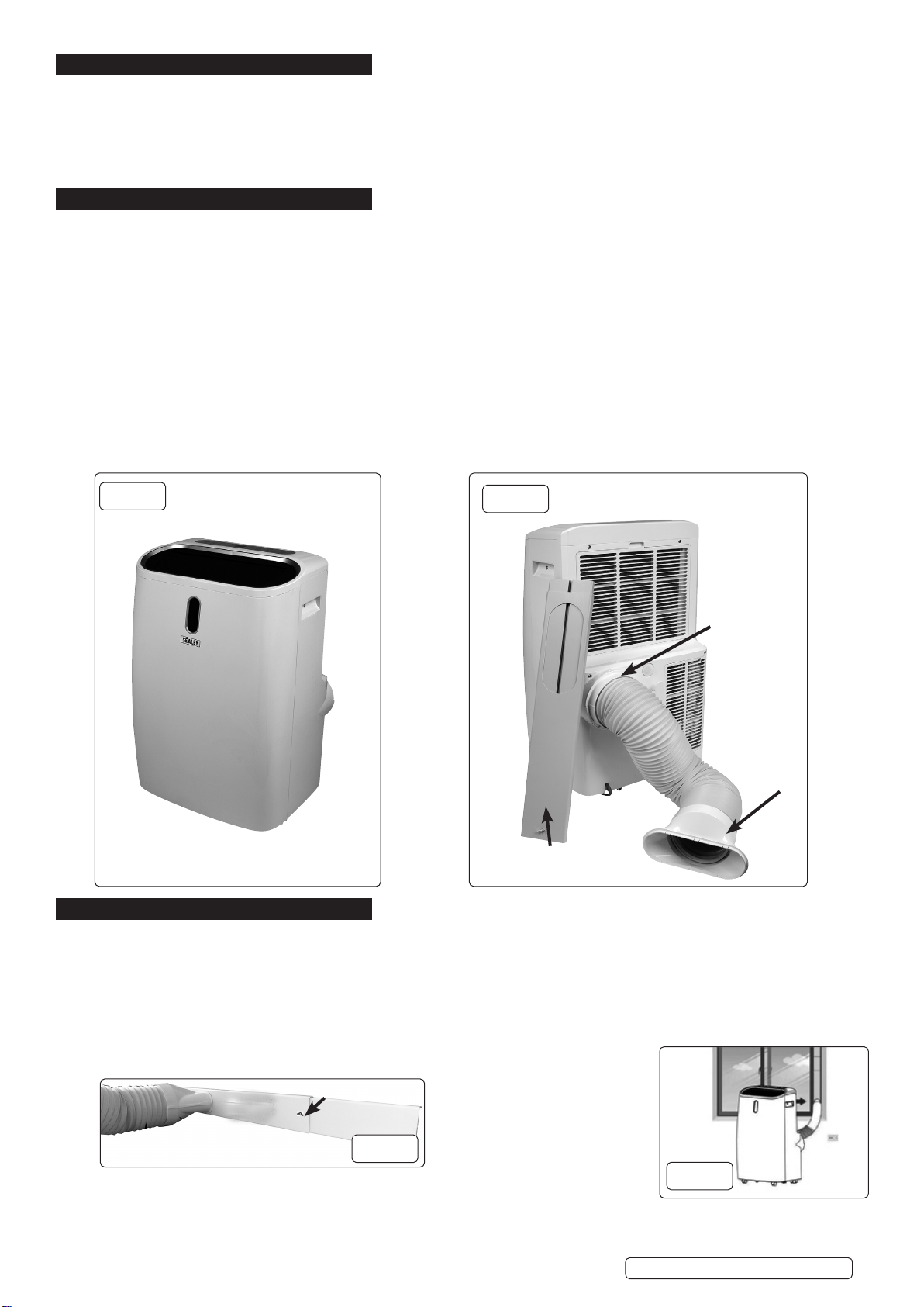
12,000BTU/HR PORTABLE AIR CONDITIONER/
DEHUMIDIFIER/AIR COOLER/HEATER WITH
WINDOW SEALING KIT
MODEL NO: SAC12000.V5, SACWK1
Thank you for purchasing a Sealey product. Manufactured to a high standard, this product will, if used according to these instructions,
and properly maintained, give you years of trouble free performance.
IMPORTANT: PLEASE READ THESE INSTRUCTIONS CAREFULLY. NOTE THE SAFE OPERATIONAL REQUIREMENTS, WARNINGS & CAUTIONS. USE
THE PRODUCT CORRECTLY AND WITH CARE FOR THE PURPOSE FOR WHICH IT IS INTENDED. FAILURE TO DO SO MAY CAUSE DAMAGE AND/OR
PERSONAL INJURY AND WILL INVALIDATE THE WARRANTY. KEEP THESE INSTRUCTIONS SAFE FOR FUTURE USE.
1. SAFETY
1.1. ELECTRICAL SAFETY
WARNING! It is the user’s responsibility to check the following:
Check all electrical equipment and appliances to ensure that they are safe before using. Inspect power supply leads, plugs and all
electrical connections for wear and damage. Sealey recommend that an RCD (Residual Current Device) is used with all electrical
products. You may obtain an RCD by contacting your local Sealey stockist.
If the product is used in the course of business duties, it must be maintained in a safe condition and routinely PAT (Portable Appliance
Test) tested.
Electrical safety information: it is important that the following information is read and understood.
1.1.1. Ensure that the insulation on all cables and on the appliance is safe before connecting it to the power supply.
1.1.2. Regularly inspect power supply cables and plugs for wear or damage and check all connections to ensure that they are secure.
1.1.3. IMPORTANT: Ensure that the voltage rating on the appliance suits the power supply to be used and that the plug is tted with the
correct fuse - see fuse rating in these instructions.
8DO NOT pull or carry the appliance by the power cable.
8DO NOT pull the plug from the socket by the cable.
8DO NOT use worn or damaged cables, plugs or connectors. Ensure that any faulty item is repaired or
replaced immediately by a qualied electrician.
1.1.4. This product is tted with a BS1363/A 3 pin plug.
If the cable or plug is damaged during use, switch the electricity supply and remove from use.
Ensure that repairs are carried out by a qualied electrician.
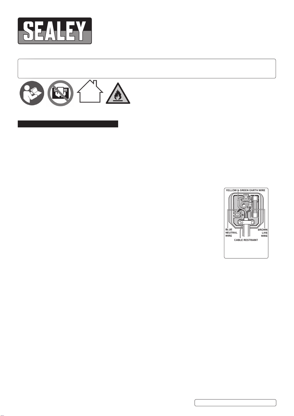
Replace a damaged plug with a BS1363/A 3 pin plug. If in doubt contact a qualied electrician.
A) Connect the GREEN/YELLOW earth wire to the earth terminal ‘E’.
B) Connect the BROWN live wire to the live terminal ‘L’.
C) Connect the BLUE neutral wire to the neutral terminal ‘N’.
Ensure that the cable outer sheath extends inside the cable restraint and that the restraint is tight.
Sealey recommend that repairs are carried out by a qualied electrician.
1.1.5. Products which require more than 13 amps are supplied without a plug. Contact a qualied electrician to ensure that a suitably rated
supply is available. Ensure that an industrial round pin plug and socket are tted by a qualied electrician.
1.1.6. If an extension cable reel is used, ensure that it is fully unwound before connection. Use a reel that includes an RCD, an appliance
will be protected by the RCD. The cable core section is important and should be at least 1.5mm2. Ensure that the cable of the reel is
appropriate for this product. We recommend the use of 2.5mm² core section cable.
1.2. GENERAL SAFETY
9Check that the unit is in sound condition and good working order. Take immediate action to repair or replace damaged parts.
Use recommended parts only. Unauthorised parts may be dangerous and will invalidate the warranty.
NOTE: Appliance is filled with R290.
9Appliance shall be installed, operated and stored in a room with a floor area larger than 12m².
8DO NOT perforate any of the components in the refrigerant circuit. Refrigerant gas may be odourless.
8DO NOT attempt any repairs / maintenance unless suitably qualied.
8DO NOT stand or place any object closer than 500mm from the unit.
8DO NOT obstruct the air intakes or outlets of the unit, and DO NOT cover with washed clothes.
8DO NOT place any object into the outlets - the unit has a fan running at high speed, contact with this will cause injury.
8DO NOT operate the unit when you are tired or under the influence of alcohol, drugs or intoxicating medication.
8DO NOT switch the unit off by disconnecting it from the mains. ALWAYS switch to the “OFF” position first.
8DO NOT remove the float lever from the water collection tank.
8DO NOT connect or disconnect the plug from the mains with wet hands.
9Always discard the water from the collection tank, DO NOT use it for any other purpose.
9Place the unit on a level and stable surface.
9To prevent water from freezing, DO NOT use the unit at ambient temperatures below 0°C.
8DO NOT use the unit outside.
9 Ensure that heating appliances are not exposed to the ow of air from the unit.
9 Before attempting to move the unit, empty the contents of the water tank. Use side carrying handles when moving unit.
9 Switch o and disconnect unit from the mains before attempting any cleaning or other maintenance work.
9 Ensure that the unit is turned o correctly when not in use, and stored in a safe, dry area, out of reach of children.
Replacement fuse
rating:13A
Refer to
instruction
manual
SAC12000.V5, SACWK1 Issue 1 09/01/23
Original Language Version
© Jack Sealey Limited
Do not cover Caution:
Risk of re
Indoor use only

2. i INTRODUCTION
4-in1 high capacity, compact, portable air conditioner, air cooling with ventilation, dehumidifying and heating functions. Thermostatically
controlled with built-in 24hr timer and sleep mode. Soft-touch control panel with LED digital display and remote control. Self-evaporating
system reuses the moisture it collects from the air to help with the cooling process allows better eciency, low maintenance and
powerful cooling. Water-full indicator with auto shut o. Supplied with extendable exhaust ducting with window kit for ventilation
and continuous drain hose. Eco-Friendly R290 refrigerant. Air conditioning temperature range 16-32°C. Washable lter. Auto-defrost
function at low ambient temperature. Mounted on castor wheels for manoeuvrability.
3. SPECIFICATION
MODEL NO:................................................SAC12000.V4
Cooling Capacity:.............................................12000Btu/hr
Discharge Side Pressure:........................................3.2MPa
Energy Rating:.................................................A (EER:2.6)
IP rating.......................................................................IPX1
Mass of refrigerant:.....................................................240g
Max. airow:..........................................................410m³/hr
Max. exhaust hose length:..........................................1.5m
Max. water extraction rate:.................................. 30.3L/day
Noise level: ............................................................65dB(A)
Power:...........................1337W (Cooling) 1118W (Heating)
Rated capacity:.............3520W (Cooling) 2780W (Heating)
Refrigerant:................................................................ R290
Suction side pressure:.............................................0.7MPa
Supply:............................................................. 230V~50Hz
4. INSTALLATION
IMPORTANT: Allow the refrigerant to settle for at least 24 hours before using the unit.
4.1. EXHAUST HOSE ASSEMBLY
4.1.1. Thread hose adaptor (g.2) onto the hose and then locate adaptor into its housing in the body.
4.1.2. Pull the free end out and screw the window adaptor onto the other end of the exhaust hose.
4.2. WINDOW ADAPTOR
4.2.1. Slide the window adaptor to the correct width for the window opening and tighten the wing nut (g.3) to stop the slide closing.
4.2.2. Close the window onto the window adaptor, clamping it in place. This can be achieved with sliding windows or vertically hinged
windows.
4.2.3. Insert the hose adaptor into the window adaptor (g.3, g.4)
8
8
8DO NOT use an extension hose or hose dierent from the one supplied. The length
and diameter of the hose supplied are the optimum size for this unit. Changing those dimensions
could aect the performance.
4.3. ATTACH WINDOW KIT ASSEMBLY SEE ALSO SECTION 8 ON WINDOW KIT INCLUDED.
g.2
Window
Fitting
Window
adaptor
Hose
Adaptor
g.1
g.4
Original Language Version
© Jack Sealey Limited
g.3
Wingnut
SAC12000.V5, SACWK1 Issue 1

4.4. LOCATION
The SAC12000 should be located on a at oor and be 500mm clear of any surrounding objects.
5. OPERATION
5.1. CONTROL PANEL AND DISPLAY
5.1.1. The display on the front face of the unit will only light when the unit is in cooling mode.
5.2. SETTINGS
5.2.1. START UP AND SHUTDOWN
5.2.1.1. Press POWER to turn the unit ON (g.5 #4).
5.2.1.2. Press MODE button to select the desired operation mode (g.5 #2).
5.2.1.3. Press POWER again to turn the unit OFF (g.5 #4).
5.2.2. OPERATION MODE
The unit has four operation modes: Cool, dehumidifier, fan and sleep.
5.2.3. COOLING A ROOM
5.2.3.1. Select the COOL mode to lower the temperature in a room.
5.2.3.2. Press MODE button (g.5 #2) until the COOL indicator illuminates (g.5 #10).
5.2.3.3. Press the UP or DOWN button (g.5 #3 #5) to adjust the temperature to the desired level. The temperature will be displayed on
the screen (g.5 #9). The temperature can be set between 16ºC to 32ºC.
5.2.3.4. Press the Speed button (g.5 #6) Until the desired fan speed indicator illuminates (g.5 #8).
NOTE: The horizontal air flow direction is controlled by adjusting the air outlet louvres (fig.1).
WARNING! The air conditioner function will stop if the room temperature is lower than the selected temperature.
5.2.4. VENTILATE THE ROOM
5.2.4.1. Press the MODE button (g.5 #2) until the FAN indicator illuminates (g.5 #10).
NOTE: In ventilation mode the room air is circulated NOT cooled.
5.2.4.2. Press the Speed button (g.5 #6) Until the desired fan speed indicator illuminates (g.5 #10).
5.2.5. DRYING THE ROOM
5.2.5.1. Press the MODE button on the control panel (g.5 #2) until the DRY indicator illuminates (g.5 #10), or press the DRY button on
the remote control (g.6).
5.2.5.2. Connect the drain hose (fig.7) To the drain outlet at the bottom of the unit (fig.6). See section 5.5.
NOTE: In this mode the fan speed is set to low level and cannot be changed.
5.2.6. SLEEP MODE
WARNING! This function can only be activated by using the SLEEP button on the remote control (g.6).
To activate the sleep mode the unit must be in the COOL mode.
5.2.6.1. To activate COOL mode press the COOL button on the remote control and then press the SLEEP (g.6).
NOTE: After 1 hour the pre-set temperature is increased by 1ºC and increased again by 1ºC the following
hour.
5.2.7. TIMER SETTING (1 to 24 hours)
5.2.7.1. The TIMER has two ways of operation and can be activated by either the button on the control panel
(g.5 #7) or by the TIMER button on the remote control (g.6).
g.6
Original Language Version
© Jack Sealey Limited
g.5
SAC12000.V5, SACWK1 Issue 1 09/01/23
1LOCK Press to turn ON or OFF the child lock function
2 MODE Press to switch operation mode between cooling,
dehumidifier and fan
3UP Increase temperature (16ºC~32ºC) or timer setting
4POWER Press to turn the unit ON or OFF
5DOWN Decreasing the temperature or timer setting
6SPEED Press to switch the fan speed between HIGH or LOW
7 TIMER Sets a time for the unit to automatically START or STOP
8FAN SPEED
INDICATOR Displays HIGH or LOW fan speed
9 DIGITAL
DISPLAY Displays timer setting and room temperature
10 MODE
INDICATOR Mode display between Cooling, Dehumidifying and Fan

5.3. AUTOMATIC DEFROST
5.3.1. At low room temperatures, frost may build up at the evaporator during operation. The unit will automatically start defrosting and the
POWER LED (g.5.4) blinking. The defrost control sequence is as follows:
5.3.2. When the unit operates in the cooling and dehum. modes and the ambient temperature sensor senses the evaporator coil temperature
is below -1°C, the compressor will stop operating for 10 minutes. The coil temperature then rises up to 7oC, the unit will restart its
operating mode.
5.3.3. When the unit operates in the heating and dehum. modes, once the coil temperature sensor senses the temperature of the evaporator
is below 40oC and the dierential temperature between coil temperature and room temperature is below 190C after the compressor has
operated for 20minutes, the unit will start defrosting for 5 minutes and the power indicator will be blinking.
5.4. OVERLOAD PROTECTION
5.4.1. In the event of a power loss, to protect the compressor, there is a three minute delay until the unit restarts.
5.5. DRAINAGE
WARNING! DO NOT attempt using either form of drainage without rst removing the power supply from the unit.
5.5.1. The unit will stop working when the water receptacle is full. See Troubleshooting section for error codes.
5.5.2. The unit has two methods of drainage. these are continuous (g.7) or manual (g.8).
5.5.3. To operate in continuous mode, remove the plastic bung in the back of the machine (g.6) and rmly insert the supplied hose.
5.5.4. Place the end of the hose over a drain or bucket and ensure that water can ow freely through it.
5.5.5. To operate in manual mode, remove the plastic bung from the lower drain (g.8). Drain water out into suitable container and
rmly replace bung when empty.
6. MAINTENANCE
NOTE: repair of unit and handling of refrigerant must only be carried out by a suitably qualied person.
6.1. GENERAL MAINTENANCE
Turn the unit OFF and disconnect it from the mains power supply before cleaning or performing maintenance.
6.1.1. Inspect the unit on a regular basis and replace or repair any damaged parts. Use recommended parts and an
authorised service agent. Unauthorised parts may be dangerous and will invalidate the warranty.
8DO NOT use any solvents or abrasive material to clean the plastic exterior of the unit. Use only a damp soft
cloth for cleaning and dry the unit afterwards with a clean, dry, soft cloth.
6.2. AIR FILTER. Clean the air lters every two weeks for optimum performance. The lters are situated at the
rear of the unit (g.8), and are held in place by plastic frames.
6.2.1. UPPER FILTER
Using the nger grip, pull the top edge gently outwards to release the holding lugs and remove the filter frame.
6.2.2. LOWER FILTER
Undo xing screw (g.8) and pull the frame gently outwards to release the holding lugs and remove lter frame.
6.2.3. Once released, vacuum the frames gently if clogged with dirt.
6.2.4. If the lter is heavily soiled, it can be washed in warm water containing a mild, neutral detergent. Ensure that the lter
is dry completely before re-installing it.
6.2.5. Retting the lter frames into the machine is the reverse order of 6.2.1./6.2.2.
6.3. STORAGE
6.3.1. If the unit is not to be used for a long period of time, drain o any water in the tank. Place a large enough container under the rear of
the unit, remove the rubber drainage stopper (g.8) to allow the tank to drain. When the tank is empty, replace the stopper rmly. Clean
the unit and air lter as above, and store in a safe, dry area, out of the reach of children.
Original Language Version
© Jack Sealey Limited
Continuous drain
location
Manual drain
location
Lower lter
xing screw
g.7 g.8
SAC12000.V5, SACWK1 Issue 1 09/01/23

Original Language Version
© Jack Sealey Limited SAC12000.V5, SACWK1 Issue 1 09/01/23
7. TROUBLE SHOOTING
WINDOW SEALING KIT FOR AIR CONDITIONER DUCTING
MODEL NO: SACWK1
8. SAFETY
8DO NOT cover the unit with this material, and do not obstruct the air inlet and outlet grilles of the machine with items such as
clothing,soft furnishings, furniture, bedding etc.
8DO NOT use the material for any purpose other than that for which it is designed.
8DO NOT use in bathroom or shower room.
8DO NOT allow children to use, when not in use,store in a safe, cool, dry, childproof area.
NOTE: This material is not intended for use by persons (including children) with reduced physical, sensory or mental capabilities or
lack of experience and knowledge, unless they have been given supervision or instruction concerning the use of the appliance by a
person responsible for their safety. Children should be supervised to ensure that they do not play with this material.
9. INTRODUCTION
Suitable for all types of hinged windows including skylights up to 300cm total perimeter. Easy to install using the supplied roll of self-
adhesive hook & loop tape. Double zip makes positioning the ducting at any height easy. Saves energy by making the air conditioner
or dryer more eective.
10. CONTENTS
Window seal
Velcro tape
Symptom Inspection Solution
The unit is not
working Check the mains supply Insert the power cord securely into the wall outlet
Check if the water level indicator lights
up? Empty the drain pan. See Section 5.5
Check the room temperature. The range of operating temperature is 5-35oC
The unit works with
reduced capacity Check if the air duct is blocked Clear the obstacle.
Check the air lter for dirt Clean the air lter. See Section 7
Check if the room door or window is open. Keep the door and windows closed.
Check if the desired operating mode is
selected and temperature is properly set. Set the mode and temperature at proper set-point
See Section 5
The exhaust hose is detached. Make sure the exhaust hose is securely attached.
Water Leakage Overow while moving the unit. Empty the water tank before transport.
Check if the drain hose is kinked or bent. Straighten the hose to avoid a trap existing.
Excessive Noise Check if the unit is securely positioned. Place the unit on horizontal and rm ground.
Check if any loose, vibrating parts. Secure and tighten the parts.
Noise sounds like water owing. Noise comes from owing refrigerant. This is normal.
Error
Codes E0 Communication faults between main PCB
and display PCB.
Check the wire harness of the display PCB for damage.
E1 Ambient temperature sensor failure Check connection or replace it. To clean or replace the
temperature sensor.
E2 Coil temperature sensor failures. Check connection or replace it. To clean or replace the
temperature sensor.
Ft Condensate water high level alarm. Empty the drain pan. See Section 5.5
Velcro tape
Window seal with zip

Original Language Version
© Jack Sealey Limited SAC12000.V5, SACWK1 Issue 1 09/01/23
11. INSTRUCTIONS
11.1. CLEANING
Clean the window and window frame, making them free from grease and dust.
11.2. CUTTING THE VELCRO TAPE TO SIZE
Cut the Velcro tape to size, using a pair of scissors. Mark the middle (M) of the window seal (Fig. 1). Mark the middle of the window
frame and the casement (Fig. 2-4) ( g. 2 shows an open window, g.3 a tilted window and g.4 an open skylight).
11.3. VELCRO TAPE TO THE WINDOW FRAME
Adhere the Velcro tape to the window frame around the window. Then adhere the Velcro tape fully around the window. Stick the Velcro
tape to the front side (in most cases 1 cm wide) of the casement or to the inner surface of the casement (where the window handle is
attached).
CAUTION: DO NOT adhere the Velcro tape on the window.
11.4. SEALING WINDOW TO WINDOW FRAME
Adhere the narrow side of the window seal to the Velcro tape on the window frame. Work from the centre and fully adhere the
narrow side all the way around. First fasten side A, then side B, starting in the middle and working all the way to the left and right.
IMPORTANT! When fastening, point A must be exactly opposite point B.
11.5. SEALING THE WINDOW
Leave the window ajar and adhere the wide side of the window seal to the Velcro tape of the window.
CAUTION: Leave sucient space, so that the window seal will not get jammed
11.6. OPENING THE WINDOW SEAL
Open the zip of the window seal approximately 50 cm. Open the zip preferably at the positions marked with “S” and attach the exhaust
air hose.
11.7. ATTACHING THE AIR DISCHARGE
Insert the air discharge hose of the air conditioning system through the hole in the window seal and close the zip until the air discharge
hose is properly secured
11.8. CLOSING THE WINDOW
If you want to close your window, simply detach the cloth from the Velcro tape. When closing the window take care that the seal is not
jammed between the casement and window frame.
NOTE: This window seal ensures that the room remains cool for a longer period of time and keeps insects and mosquitoes out.
POLYESTER
MATERIAL
M= MIDDLE g.1
g.2
OPEN WINDOW
g.3
TILTED WINDOW
OPEN SKYLIGHT g.4

11.9. The installed item will resemble g.5 and g.6.
Original Language Version
© Jack Sealey Limited
Sealey Group, Kempson Way, Suffolk Business Park, Bury St Edmunds, Suffolk. IP32 7AR
01284 757500 sales@sealey.co.uk www.sealey.co.uk
ENVIRONMENT PROTECTION
Recycle unwanted materials instead of disposing of them as waste. All tools, accessories and packaging should be
sorted, taken to a recycling centre and disposed of in a manner which is compatible with the environment. When
the product becomes completely unserviceable and requires disposal, drain any fluids (if applicable) into approved
containers and dispose of the product and fluids according to local regulations.
Note: It is our policy to continually improve products and as such we reserve the right to alter data, specifications and component parts without prior
notice. Please note that other versions of this product are available. If you require documentation for alternative versions, please email or call
our technical team on technical@sealey.co.uk or 01284 757505.
Important: No Liability is accepted for incorrect use of this product.
Warranty: Guarantee is 12 months from purchase date, proof of which is required for any claim.
WEEE REGULATIONS
Dispose of this product at the end of its working life in compliance with the EU Directive on Waste Electrical and Electronic Equipment
(WEEE). When the product is no longer required, it must be disposed of in an environmentally protective way. Contact your local solid
waste authority for recycling information.
BATTERY REMOVAL
Under the Waste Batteries and Accumulators Regulations 2009, Jack Sealey Ltd are required to inform potential purchasers of products
containing batteries (as defined within these regulations), that they are registered with Valpak’s registered compliance scheme. Jack
Sealey Ltd Batteries Producer Registration Number (BPRN) is BPRN00705.
SAC12000.V5, SACWK1 Issue 1 09/01/23
g.5 g.6
REGISTER YOUR
PURCHASE HERE
This manual suits for next models
1
Table of contents
Other Sealey Air Conditioner manuals

Sealey
Sealey SAC41.V2 User manual

Sealey
Sealey SAC9000 User manual

Sealey
Sealey SAC13 User manual

Sealey
Sealey SAC125 User manual

Sealey
Sealey SAC7000 User manual

Sealey
Sealey SAC12000.V4 User manual

Sealey
Sealey SAC12000.V2 User manual

Sealey
Sealey SAC9002.V3 User manual

Sealey
Sealey Sac9001 User manual

Sealey
Sealey SAC04 User manual

Sealey
Sealey sac9000.V3 User manual

Sealey
Sealey SAC12000.V3 User manual

Sealey
Sealey SAC9002.V2 User manual

Sealey
Sealey SAC7000.V2 User manual

Sealey
Sealey SAC9002 User manual

Sealey
Sealey SAC12000 User manual

Sealey
Sealey SAC9000.V2 User manual

Sealey
Sealey SAC41.V3 User manual

Sealey
Sealey SAC41 User manual