Sealey SAC12000.V3 User manual

Our Address
Puravent, Adremit Limited, Unit 5a, Commercial Yard,
Settle, North Yorkshire, BD24 9RH
Get In Touch
Call: 0845 6880112
Email: [email protected]
AIR CONDITIONER/DEHUMIDIFIER/HEATER
MODEL NO: SAC12000.V3
Thank you for purchasing a Sealey product. Manufactured to a high standard, this product will, if used according to these instructions,
and properly maintained, give you years of trouble free performance.
IMPORTANT: PLEASE READ THESE INSTRUCTIONS CAREFULLY. NOTE THE SAFE OPERATIONAL REQUIREMENTS, WARNINGS & CAUTIONS. USE
THE PRODUCT CORRECTLY AND WITH CARE FOR THE PURPOSE FOR WHICH IT IS INTENDED. FAILURE TO DO SO MAY CAUSE DAMAGE AND/OR
PERSONAL INJURY AND WILL INVALIDATE THE WARRANTY. KEEP THESE INSTRUCTIONS SAFE FOR FUTURE USE.
1. SAFETY
1.1. ELECTRICAL SAFETY
WARNING! It is the user’s responsibility to check the following:
Check all electrical equipment and appliances to ensure that they are safe before using. Inspect power supply leads, plugs and all
electrical connections for wear and damage. Sealey recommend that an RCD (Residual Current Device) is used with all electrical
products. You may obtain an RCD by contacting your local Sealey dealer.
If the product is used in the course of business duties, it must be maintained in a safe condition and routinely PAT (Portable Appliance
Test) tested.
Electrical safety information: it is important that the following information is read and understood.
1.1.1. Ensure that the insulation on all cables and on the appliance is safe before connecting it to the power supply.
1.1.2. Regularly inspect power supply cables and plugs for wear or damage and check all connections to ensure that they are secure.
1.1.3. IMPORTANT: Ensure that the voltage rating on the appliance suits the power supply to be used and that the plug is tted with the
correct fuse - see fuse rating in these instructions.
8DO NOT pull or carry the appliance by the power cable.
8DO NOT pull the plug from the socket by the cable.
8DO NOT use worn or damaged cables, plugs or connectors. Ensure that any faulty item is repaired or
replaced immediately by a qualied electrician.
1.1.4. This product is tted with a BS1363/A 13 Amp 3 pin plug.
If the cable or plug is damaged during use, switch the electricity supply and remove from use.
Ensure that repairs are carried out by a qualied electrician.
Replace a damaged plug with a BS1363/A 13 Amp 3 pin plug. If in doubt contact a qualied electrician.
A) Connect the GREEN/YELLOW earth wire to the earth terminal ‘E’.
B) Connect the BROWN live wire to the live terminal ‘L’.
C) Connect the BLUE neutral wire to the neutral terminal ‘N’.
Ensure that the cable outer sheath extends inside the cable restraint and that the restraint is tight.
Sealey recommend that repairs are carried out by a qualied electrician.
1.1.5. Products which require more than 13 amps are supplied without a plug. Contact a qualied electrician to ensure that a suitably rated
supply is available. Ensure that an industrial round pin plug and socket are tted by a qualied electrician.
1.1.6. If an extension cable reel is used, ensure that it is fully unwound before connection. Use a reel that includes an RCD, an appliance
will be protected by the RCD. The cable core section is important and should be at least 1.5mm2. Ensure that the cable of the reel is
appropriate for this product. We recommend the use of 2.5mm² core section cable.
1.2. GENERAL SAFETY
9Check that the unit is in sound condition and good working order. Take immediate action to repair or replace damaged parts.
Use recommended parts only. Unauthorised parts may be dangerous and will invalidate the warranty.
NOTE: Appliance is filled with R290.
9Appliance shall be installed, operated and stored in a room with a floor area larger than 14.4m².
8DO NOT perforate any of the components in the refrigerant circuit. Refrigerant gas may be odourless.
8DO NOT attempt any repairs / maintenance unless suitably qualied.
8DO NOT stand or place any object closer than 500mm from the unit.
8DO NOT obstruct the air intakes or outlets of the unit, and DO NOT cover with washed clothes.
8DO NOT place any object into the outlets - the unit has a fan running at high speed, contact with this will cause injury.
8DO NOT operate the unit when you are tired or under the influence of alcohol, drugs or intoxicating medication.
8DO NOT switch the unit off by disconnecting it from the mains. ALWAYS switch to the “OFF” position first.
8DO NOT remove the float lever from the water collection tank.
8DO NOT connect or disconnect the plug from the mains with wet hands.
9Always discard the water from the collection tank, DO NOT use it for any other purpose.
9Place the unit on a level and stable surface.
9To prevent water from freezing, DO NOT use the unit at ambient temperatures below 0°C.
8DO NOT use the unit outside.
9 Ensure that heating appliances are not exposed to the ow of air from the unit.
9 Before attempting to move the unit, empty the contents of the water tank. Use side carrying handles when moving unit.
9 Switch o and disconnect unit from the mains before attempting any cleaning or other maintenance work.
9 Ensure that the unit is turned o correctly when not in use, and stored in a safe, dry area, out of reach of children.
Replacement fuse
rating:13A
Refer to
instruction
manual
SAC12000.V3 Issue 1 11/03/20
Original Language Version
© Jack Sealey Limited
Do not cover Caution:
Risk of re
Indoor use only
Our Address
Puravent, Adremit Limited, Unit 5a, Commercial Yard,
Settle, North Yorkshire, BD24 9RH
Get In Touch
Call: 0845 6880112
Email: [email protected]
2. i INTRODUCTION
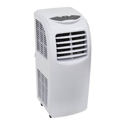
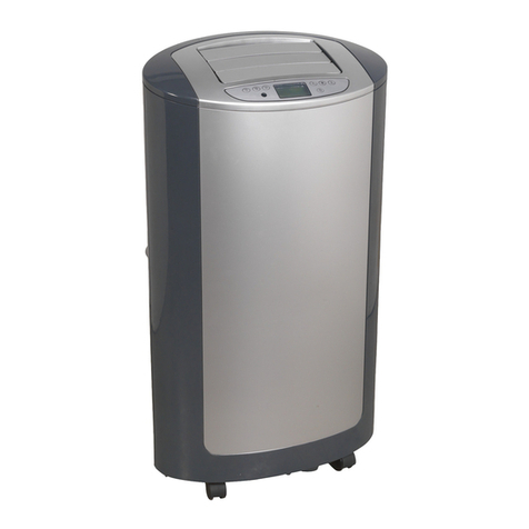
Thermostatically controlled unit with extendible exhaust hose and window kit - ideal for home or oce environments. Features three-speed fan
and electronic remote control. Air conditioning temperature range 16-30°C. Also features heating and dehumidifying functions. Dehumidier
capable of removing up to 28.8L/day. Refrigerant is R290 300g. Mounted on castors for manoeuvrability. Cable storage keeps unit tidy when not
in use.
3. SPECIFICATION
MODEL NO:...................................................SAC12000.V3
Cooling Capacity:................................................12000Btu/hr
Discharge Side Pressure: ..........................................2.8MPa
Energy Class:...................................A (Cooling) A+ (Heating)
IP rating ..........................................................................IP20
Mass of refrigerant: ........................................................ 300g
Max. airow:.............................................................435m³/hr
Max. exhaust hose length: ............................................. 1.5m
Max. water extraction rate:..................................... 28.8L/day
Noise level: .............................................................. 65db (A)
Power:..............................1340W (Cooling) 1235W (Heating)
Rated capacity: ................3500W (Cooling) 3250W (Heating)
Refrigerant: ................................................................... R290
Suction side pressure: ...............................................0.8MPa
Supply:................................................................ 230V~50Hz
4. INSTALLATION
IMPORTANT: Allow the refrigerant to settle for at least 24 hours before using the unit.
4.1. EXHAUST HOSE ASSEMBLY
4.1.1. Snap the two halves of the hose adaptor (g.1.13) together (DO NOT use excessive force).
4.1.2. Pull one end exhaust hose (g1.14) out from its closed position.
4.1.3. Insert the end into the exhaust air outlet (g.1.8) and turn in an anticlockwise direction until tight.
4.1.4. Pull the free end out and screw the assembled hose adaptor onto the outer end of the exhaust hose in an anticlockwise direction until
tight.
4.2. WINDOW ADAPTOR
4.2.1. Slide the window adaptor to the correct width for the window opening and locate the stop screw in the relevant screw hole to stop the
slide closing.
4.2.2. Close the window onto the window adaptor, clamping it in place. This can be achieved with sash windows, sliding windows or vertically
hinged windows.
4.2.3. Insert the hose adaptor into the window adaptor (gs 2 and 3).
8DO NOT use an extension hose or hose dierent from the one supplied. The length
and diameter of the hose supplied are the optimum size for this unit. Changing those
dimensions could aect the performance.
4.3. LOCATION
The SAC12000 should be located on a at oor and be 500mm clear of any surrounding objects.
g.1
g.3
g.2
Original Language Version
© Jack Sealey Limited SAC12000.V3 Issue 1 11/03/20

Our Address
Puravent, Adremit Limited, Unit 5a, Commercial Yard,
Settle, North Yorkshire, BD24 9RH
Get In Touch
Call: 0845 6880112
Email: [email protected]
5. OPERATION
5.1. CONTROL FUNCTIONS (FIG.4, FIG.5)
5.1.1. When connected to mains power, the unit enters standby status. The display shows the ambient temperature if between 5-35°C/41-
95°If below this range, the display will show ‘L’; if above it will show ‘H’.
5.1.2. On/O Button : When this button is pressed, the unit will enter cooling mode (the default temperature setting is 24°C/75°F). A
further press of the button and the machine will revert to standby status.
5.1.3. Mode Button : Scroll through by repeatedly pressing this button for Cooling, Fan, Heating or Dehumidier mode (gs.8 / 9 / 10 / 11).
5.1.4. Fan Button : Scroll through by repeatedly pressing to obtain: High Speed, Medium Speed, Low Speed.
5.1.5. Timer Button :On the rst press the icon will show in the display, along with ‘0hr’. Using the and buttons adjust the
hour either up or down, the minute setting will ash after a short pause and can be adjusted up or down until the required time is
reached. The icon will show until the machine switches on after the set period. When the unit is running, setting the timer will switch
it o after the required period.
5.1.6. The and buttons can be used to set either time or temperature. If pressed simultaneously, the temperature display can be changed
from °C to °F.
5.1.7. Press button to start the outlet louvres oscillating; a second press will stop them.
5.2. REMOTE CONTROL
5.2.1. The remote control requires 2 x AAA 1.5V batteries which are tted and removed by sliding the battery compartment cover open and
inserting the batteries in the compartment. Ensure the correct polarity of the batteries.
5.2.2. The icons on the remote control are identical to those on the control panel as
described in section 5.1. above, and full the same functions. The only dierence is
the Temperature °C↔°F button which allows the temperature scale to be altered.
5.3. SELF PROTECTION FEATURES
5.3.1. Freezing Protection.
During low ambient temperature conditions the unit will stop working when in the
cooling mode. The display will show ‘E4’. When the temperature rises, the previous setting
is resumed.
5.3.2. Full Water Tank.
If the water tank becomes full, FL will ash on the display. See section 5.4 for remedy.
5.3.3. Compressor Delay.
Except when starting up for the rst time, there is a 3 minute delay before the compressor
starts running.
5.3.4. Low Refrigerant.
When the unit senses a low refrigerant condition (by comparing inlet and output
temperatures) it will shut the compressor and water pump down and the fan speed will
drop to minimum setting. The display will show ‘E3’.
5.4. WATER DRAINAGE.
Under normal circumstances, the unit will evaporate the condensate produced and discharge it along with the exhaust air.
5.4.1. If the machine shuts down because of excess water in the drain tank (as in 5.3.2.), disconnect from mains power. Move the machine
slowly to avoid spilling condensate. Drain the tank (g.7) by unscrewing the drain cap, removing the drain plug and draining the
collected water into a suitable container or drain.
5.4.2. Ret the drain plug and drain cap; reconnect to the mains power and continue using.
NOTE: Water will still collect in the drain tank even when the unit is in the heating mode; check the tank and drain regularly.
5.5. LED DISPLAY GUIDE.
5.5.1. Air Con. mode (g.8).
g.5
g.7
g.8
g.4
g.6
Original Language Version
© Jack Sealey Limited SAC12000.V3 Issue 1 11/03/20

Our Address
Puravent, Adremit Limited, Unit 5a, Commercial Yard,
Settle, North Yorkshire, BD24 9RH
Get In Touch
Call: 0845 6880112
Email: [email protected]
5.5.2. Fan only mode (g.9).
5.5.3. Dehumidifying mode (g.10).
5.5.4. Heating mode (g.11).
6. MAINTENANCE
NOTE: repair of unit and handling of refrigerant must only be carried out by a suitably qualied person.
6.1. GENERAL MAINTENANCE
Turn the unit OFF and disconnect it from the mains power supply before cleaning or performing any maintenance.
6.1.1. Inspect the unit on a regular basis and replace or repair any damaged parts. Use recommended parts and an authorised service
agent. Unauthorised parts may be dangerous and will invalidate the warranty.
8DO NOT use any solvents or abrasive material to clean the plastic exterior of the unit. Use only a damp soft cloth for cleaning and dry
the unit afterwards with a clean, dry, soft cloth.
6.2. AIR FILTERS. Clean the air lters every two weeks for optimum performance. The lters are situated at the rear of the unit (gs.12
and 13), and are held in place by plastic frames.
6.2.1. Upper Filter
Pull the top handle gently to release the holding lugs and remove the filter frame.
6.2.2. Lower Filter
Pull the corner handle gently to release the holding lugs and remove the lter frame.
6.2.3. Once released, remove the lter from the frame and tap it gently to remove dust, or vacuum it gently if it is very clogged with dirt.
6.2.4. If the lter is heavily soiled, it can be washed in warm water containing a mild, neutral detergent. Ensure that the lter is dry completely
before installing it.
6.2.5. To replace the lter, rst insert the two bottom tags of the lter frame into the bottom edge of the lter frame recess in the unit. Lay the
lter into the lter frame and hinge the frame forwards into the recess. Push the top of the frame inwards until the two clips snap into
place.
6.2.6. Retting the lter frames into the machine is the opposite of 6.2.1./6.2.2.
6.3. STORAGE
6.3.1. If the unit is not to be used for a long period of time, drain o any water in the tank. Place a large enough container under the rear of
the unit, remove the rubber drainage stopper (g.7) to allow the tank to drain. When the tank is empty, replace the stopper rmly. Clean
the unit and air lter as above, and store in a safe, dry area, out of the reach of children.
g.9
g.10
g.11
g.12 g.13
Original Language Version
© Jack Sealey Limited SAC12000.V3 Issue 1 11/03/20

Our Address
Puravent, Adremit Limited, Unit 5a, Commercial Yard,
Settle, North Yorkshire, BD24 9RH
Get In Touch
Call: 0845 6880112
Email: [email protected]
Sealey Group, Kempson Way, Suffolk Business Park, Bury St Edmunds, Suffolk. IP32 7AR
01284 757500 01284 703534 sales@sealey.co.uk www.sealey.co.uk
ENVIRONMENT PROTECTION
Recycle unwanted materials instead of disposing of them as waste. All tools, accessories and packaging should be sorted, taken to
a recycling centre and disposed of in a manner which is compatible with the environment. When the product becomes completely
unserviceable and requires disposal, drain any fluids (if applicable) into approved containers and dispose of the product and fluids
according to local regulations.
Note: It is our policy to continually improve products and as such we reserve the right to alter data, specifications and component parts without prior
notice. Please note that other versions of this product are available. If you require documentation for alternative versions, please email or call
our technical team on technical@sealey.co.uk or 01284 757505.
Important: No Liability is accepted for incorrect use of this product.
Warranty: Guarantee is 12 months from purchase date, proof of which is required for any claim.
WEEE REGULATIONS
Dispose of this product at the end of its working life in compliance with the EU Directive on Waste Electrical and Electronic Equipment
(WEEE). When the product is no longer required, it must be disposed of in an environmentally protective way. Contact your local solid
waste authority for recycling information.
BATTERY REMOVAL
Under the Waste Batteries and Accumulators Regulations 2009, Jack Sealey Ltd are required to inform potential purchasers of products
containing batteries (as defined within these regulations), that they are registered with Valpak’s registered compliance scheme. Jack
Sealey Ltd Batteries Producer Registration Number (BPRN) is BPRN00705.
Original Language Version
© Jack Sealey Limited SAC12000.V3 Issue 1 11/03/20
Table of contents
Other Sealey Air Conditioner manuals

Sealey
Sealey SAC41 User manual

Sealey
Sealey SAC41.V2 User manual

Sealey
Sealey sac9000.V3 User manual

Sealey
Sealey SAC7000.V2 User manual

Sealey
Sealey SAC12000.V5 User manual

Sealey
Sealey SAC7000 User manual

Sealey
Sealey SAC41.V3 User manual

Sealey
Sealey SAC9000.V2 User manual

Sealey
Sealey SAC13 User manual

Sealey
Sealey SAC12000.V2 User manual
Popular Air Conditioner manuals by other brands

Samsung
Samsung AQV12J Series user manual

Mitsubishi Electric
Mitsubishi Electric MSZ-FA25VA Service manual

Panasonic
Panasonic CS-LZ9ZKA operating instructions

LG
LG A2UN186FA0 Service manual

Toshiba
Toshiba RAS-10J2KV-HK owner's manual

GD Midea Refrigeration Equipment
GD Midea Refrigeration Equipment Elite Series Technical & service manual