Sealey SAC9002 User manual

9,000BTU/HR AIR CONDITIONER/DEHUMIDIFIER
MODEL NO: SAC9002
Thank you for purchasing a Sealey product. Manufactured to a high standard, this product will, if used according to these
instructions, and properly maintained, give you years of trouble free performance.
IMPORTANT: PLEASE READ THESE INSTRUCTIONS CAREFULLY. NOTE THE SAFE OPERATIONAL REQUIREMENTS, WARNINGS & CAUTIONS. USE
THE PRODUCT CORRECTLY AND WITH CARE FOR THE PURPOSE FOR WHICH IT IS INTENDED. FAILURE TO DO SO MAY CAUSE DAMAGE AND/OR
PERSONAL INJURY AND WILL INVALIDATE THE WARRANTY. KEEP THESE INSTRUCTIONS SAFE FOR FUTURE USE.
1. SAFETY
1.1. ELECTRICAL SAFETY
WARNING! It is the user’s responsibility to check the following:
Check all electrical equipment and appliances to ensure that they are safe before using. Inspect power supply leads, plugs and all
electrical connections for wear and damage. Sealey recommend that an RCD (Residual Current Device) is used with all electrical
products. You may obtain an RCD by contacting your local Sealey stockist.
If the product is used in the course of business duties, it must be maintained in a safe condition and routinely PAT (Portable
Appliance Test) tested.
Electrical safety information: it is important that the following information is read and understood.
1.1.1. Ensure that the insulation on all cables and on the appliance is safe before connecting it to the power supply.
1.1.2. Regularly inspect power supply cables and plugs for wear or damage and check all connections to ensure that they are secure.
1.1.3. IMPORTANT: Ensure that the voltage rating on the appliance suits the power supply to be used and that the plug is tted with the
correct fuse - see fuse rating in these instructions.
8DO NOT pull or carry the appliance by the power cable.
8DO NOT pull the plug from the socket by the cable.
8DO NOT use worn or damaged cables, plugs or connectors. Ensure that any faulty item is repaired or
replaced immediately by a qualied electrician.
1.1.4. This product is tted with a BS1363/A 13 Amp 3 pin plug.
If the cable or plug is damaged during use, switch the electricity supply and remove from use.
Ensure that repairs are carried out by a qualied electrician.
Replace a damaged plug with a BS1363/A 13 Amp 3 pin plug. If in doubt contact a qualied electrician.
A) Connect the GREEN/YELLOW earth wire to the earth terminal ‘E’.
B) Connect the BROWN live wire to the live terminal ‘L’.
C) Connect the BLUE neutral wire to the neutral terminal ‘N’.
Ensure that the cable outer sheath extends inside the cable restraint and that the restraint is tight.
Sealey recommend that repairs are carried out by a qualied electrician.
1.1.5. Products which require more than 13 amps are supplied without a plug. Contact a qualied electrician to ensure that a suitably rated
supply is available. Ensure that an industrial round pin plug and socket are tted by a qualied electrician.
1.1.6. If an extension cable reel is used, ensure that it is fully unwound before connection. Use a reel that includes an RCD, an appliance
will be protected by the RCD. The cable core section is important and should be at least 1.5mm2. Ensure that the cable of the reel is
appropriate for this product. We recommend the use of 2.5mm² core section cable.
1.2. GENERAL SAFETY
9Check that the unit is in sound condition and good working order. Take immediate action to repair or replace damaged parts.
Use recommended parts only. Unauthorised parts may be dangerous and will invalidate the warranty.
NOTE: Appliance is filled with propane gas R290.
NOTE: Only install, operate or store in a room with a floor area greater than 12.92m2.
8DO NOT attempt any repairs / maintenance unless suitably qualified.
8DO NOT stand or place any object closer than 500mm from the unit.
8DO NOT obstruct the air intakes or outlets of the unit, and DO NOT cover with washed clothes.
8DO NOT place any object into the outlets - the unit has a fan running at high speed, contact with this will cause injury.
8DO NOT operate the unit when you are tired or under the influence of alcohol, drugs or intoxicating medication.
8DO NOT switch the unit off by disconnecting it from the mains. ALWAYS switch it off using the Power button.
8DO NOT remove the float lever from the water collection tank.
8DO NOT connect or disconnect the plug from the mains with wet hands.
8DO NOT use the unit outside.
8DO NOT install or operate this air conditioner in a bathroom or other wet environments.
9To prevent water from freezing, DO NOT use the unit at ambient temperatures below 0°C.
9Always discard the water from the collection tank, DO NOT use it for any other purpose.
9Place the unit on a level and stable surface.
9 Ensure that heating appliances are not exposed to the ow of air from the unit.
Replacement fuse
rating:13A
SAC9002 Issue 1 19/03/20
Original Language Version
© Jack Sealey Limited
Refer to
instructions
Do not cover Indoor use only Caution:
Risk of re

9 Before attempting to move the unit, empty the contents of the water tank. Use carrying handle (g1.10)when moving unit.
9 Switch o and disconnect unit from the mains before attempting any cleaning or other maintenance work.
9 Ensure that the unit is turned o correctly when not in use, and stored in a safe, dry area, out of reach of children.
NOTE: This appliance can be used by children aged from 8 years and above and persons with reduced physical, sensory or
mental capabilities or lack of experience and knowledge if they have been given supervision or instruction concerning use of
the appliance in a safe way and understand the hazards involved. Children shall not play with the appliance. Cleaning and user
maintenance shall not be made by children without supervision.
2. INTRODUCTION
Thermostatically controlled unit with extendible exhaust hose and window kit - ideal for home or oce environments. Features
two-speed fan and electronic remote control. Air conditioning temperature range 16-30°C. Also features a dehumidifying
function capable of removing up to 24L/day. Refrigerant is R290. Mounted on castors for manoeuvrability. Cable storage keeps unit
tidy when not in use.
3. SPECIFICATION
Model No.:..............................................................SAC9002
Cooling capacity:...................................................9000Btu/hr
Discharge side pressure: ...........................................3.8MPa
Energy rating: ...................................................... A (Cooling)
IP rating: .........................................................................IP20
Mass of refrigerant: ........................................................ 270g
Max. airow:.............................................................360m³/hr
Max. exhaust hose length: ............................................. 1.5m
Max water extraction rate:......................................... 24L/day
Noise level: .............................................................. 65db (A)
Power:.........................................................................1010W
Rated capacity: ...........................................................2640W
Refrigerant: ................................................................... R290
Suction side pressure: ............................................... 1.3Mpa
Supply:................................................................ 230V~50Hz
4. CONTENTS (SEE FIG.1)
5. INSTALLATION
WARNING! leave this mobile air-conditioner in an upright position for at least 2 hours before rst use. Ensure that the air
conditioner remains in an upright position whilst it is being moved. Place the air-conditioner on a at ground surface.
5.1. Connector g.1.24 and Window sealing board assembly g.1.26 are tted to Exhaust Hose g.1.25. Place 25 and 26 at each end of
the hose and screw clockwise onto the hose to connect.
5.2. Select the exhaust hose retaining clamp.
5.3. Fit the exhaust hose to the circular aperture at the rear and secure with the retaining clip.
5.4. Rotate the retaining clip anticlockwise and snap the retaining clamp closed to secure the heat exhaust hose.
Original Language Version
© Jack Sealey Limited SAC9002 Issue 1 19/03/20
1 Control panel 14 Lower air duct bottom
2 Horizontal louvre 15 Wire-winding post
3 Vertical louvre 16 Drain cap
4 Air outlet frame 17 Evaporator lter mesh
5 Vertical Louvre connecting lever 18 Evaporator lter frame
6Caster 19 Radiating ne mesh
7 Horizontal louvre connecting lever 20 Condenser lter mesh
8 Main vertical louvre 21 Condenser lter frame
9Front shell 22 Base plate
10 Handle position (right side: remote control storage area) 23 Remote control
11 Back shell 24 Heat exhaust hose short connector
12 Retaining clip (exhaust hose) 25 Exhaust hose
13 Power cord 26 Window sealing board assembly
fig.1
fig.2
fig.3 fig.4

5.5. Fit 26 window sealing board to the window as shown in g 3 (vertical) or g 4 (horizontal).
5.6. Position the mobile air-conditioner, with the exhaust hose assembly attached, near to a window. Keep the mobile air conditioner at
least 50cm away from the walls or other objects. (As shown in g 5)
5.7. Snap the at end of the exhaust hose connector into the elliptical hole of the window sealing board assembly (g 3, g 4).
5.8. To ensure adequate operation, ensure that the exhaust hose is not kinked, DO NOT bend the exhaust hose any more than 45°.
IMPORTANT:
The exhaust hose is 280mm-1500mm long and this length is determined based on the specication of the air-conditioner. DO
NOT use hoses with other specications. DO NOT replace with non-genuine components as this may aect the functions of the
air-conditioner. The ow of exhaust must be smooth. Obstructed exhaust may cause the air-conditioner to overheat.
6. OPERATION
6.1. CONTROL PANEL FUNCTIONALITY (g.4)
6.1.1. This unit has three functions: cooling, dehumidifying and fan which are accessed by use of a ‘Mode’ button on the control panel.
6.2. POWER BUTTON
6.2.1. The Power button is used to start / shut down the unit. When used to start the unit, the last mode set will be activated.
6.2.2. When the unit is rst turned on an audible signal is emitted and the central display will show the ambient temperature. If the ambient
is below 100C or above 350 C the unit enters a standby sate and displays either ‘L’ or ‘H’ respectively in the central display.
6.3. COOLING MODE
6.3.1. To engage the cooling function, press the Mode button to cycle through the indicator display until the ‘Cool’ light is turned on.
6.3.2. The cooling Fan speed may be set to high or low by pressing the ‘Fan’ button on the display. The relevant LED will show the setting.
6.3.3. The cooling temperature can be set using the ‘up’ and ‘down’ arrows and will be shown in the LED display window.
6.3.4. Temperatures can be displayed in either Centigrade or Fahrenheit by pressing both up and down arrows simultaneously.
6.4. DEHUMIDIFYING MODE
6.4.1. To engage the dehumidifying function, press the Mode button to cycle through the indicator display until the ‘Dry’ light is turned on.
6.4.2. If the ambient temperature is 170C or higher, the compressor will start. If the ambient temperature falls below 150C it will shut down.
6.4.3. The fan speed in this mode is set to low level and cannot be altered.
6.5. FAN MODE
6.5.1. To engage the Fan function, press the Mode button to cycle through the indicator display until the ‘Fan’ light is turned on.
6.5.2. In this mode the fan speed is controlled (high or low) by pressing the ‘Fan’ button to cycle between the two states.
6.6. TIMER MODE
6.6.1. The timing function can be used to either end a process after a period of time or start one after a period of time. Time units are single
hours i.e. 1 hour, 3 hours etc. and are set by use of the up and down arrows to increase or decrease the time period.
6.6.2. To use the timer to end a program after a set time, rst set up your parameters i.e. Fan / High, then select ‘Timer’ and set your required
run-time period.
6.6.3. To use the timer to create a delayed start, rst set up your parameters i.e. Fan / High, select ‘Timer’ and set your required wait-time
period. Press the Power button to put the unit into Sleep mode. When the set time has passed the unit will start the pre-set program.
6.6.4. To query remaining time for a set operation press the Timer button once.
6.6.5. To cancel a time setting, press the Timer button twice in quick succession.
Original Language Version
© Jack Sealey Limited SAC9002 Issue 1 19/03/20
fig.5
fig.7fig.6

6.6.6. Turning the unit o will clear all timing settings currently in use.
6.7. UNIT DISPLAY
6.7.1. To change the temperature units displayed, depress both up and down arrows simultaneously. ‘0C’ or ‘0F’ will be displayed in the
central display.
6.8. REMOTE CONTROL (g.5)
6.8.1. The operation instructions of the buttons of this simple remote control are as follows:
6.8.2. Power button: press this button to turn on/o the unit;
6.8.3. Timer button: upon shutdown, press this button to set timed start; upon start, press this button to set timed shutdown.
6.8.4. High button: press this button to allow the unit to operate in the high fan speed state (except in the dry and sleep modes);
6.8.5. Low button: press this button to allow this unit to operate in the low fan speed state;
6.8.6. Up button: press this button to increase the temperature and timing value;
6.8.7. Down button: press this button to decrease the temperature and timing value;
6.8.8. 0C — 0F button: press this button to switch between the Celsius degree and Fahrenheit degree;
6.8.9. Cool button: press this button to set this unit to operate in the cooling mode;
6.8.10. Fan button: press this button to set this unit to operate in the air supply mode;
6.8.11. Dry button: press this button to set this unit to operate in the dry mode;
6.8.12. Sleep mode: press this button to set this unit to operate in the sleep mode. Press again to wake unit up. The program that was
running when Sleep was selected will recommence from the condition which it was in when ‘sleep’ was selected.
6.9. PROTECTION FUNCTIONS
6.9.1. ANTI-FREEZE PROTECTION FUNCTION:
Upon cooling, when the compressors operates continuously for more than 10 minutes, if the pipe temperature Tp is less than or equal
to 20C continuously for 20 seconds, the compressor and water spraying motor turn o, other loads operate and LED displays E4, the
unit initiates the anti-frost protection function and the buttons are inactive (except the OFF button). Once the pipe temperature rises to
exceed or equal 80C, the protection is relieved, the original status is restored and the unit meets the requirements for 3-minute delay
protection of the compressor.
6.9.2. FULL WATER PROTECTION FUNCTION:
When the water in the water tray exceeds the alarm level, the unit will alarm automatically and the full water indicator illuminates on the
control panel In this case, you need to drain the condensate in the unit; otherwise, the unit will shut down automatically after the buzzer
gives o 5 beeps. If the unit is not shut down manually, the unit will be restored to the previous operating status automatically once the
water is fully drained. Or the power may be turned on again to start the unit.
6.9.3. DELAY PROTECTION FUNCTION OF THE COMPRESSOR:
This unit oers restart protection for the compressor. Except that the compressor may start immediately when the unit is energized for
the rst time, there is 3-minute delay start protection after the compressor is shut down. After the compressor operates continuously for
10 minutes, if the pipe temperature sensor detects that the dierence between the pipe temperature and room temperature is less than
30C for 30 minutes continuously, the unit enters uorine-free protection, the compressor and water spraying motor turn o, and the fan
operates in the low speed mode and E3 is displayed.
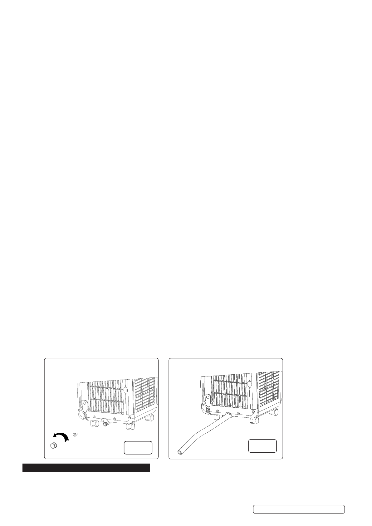
6.10. WATER DRAINAGE
6.10.1. MANUAL DRAIN: (g.6)
6.10.1.1. If the unit shuts down upon full water (‘Full’ light illuminated on control panel), turn o the power to the unit and then unplug from
the electrical supply.
NOTE: Move the unit carefully to avoid spillage of water in the water tray at the bottom of the unit.
6.10.1.2. Put the draining vessel below the water outlet at the back of the unit. Screw o the drain cap, unplug the water plug and drain
the water into a suitable container. Tilt the unit slightly backward when draining. Once the water is fully drained, re-insert the water plug
and screw on the water cap tightly.
NOTE: Turn on the unit only after the water plug and drain cap are installed properly, otherwise, the condensate of the unit will ow
onto the ground or carpet.
6.10.2. CONTINUOUS DRAIN: (g.7)
6.10.2.1. Remove the water cap in the direction shown by the arrow (g.6) and unplug the water plug;
6.10.2.2. Insert the13mm OD PVC drain hose 8mm-10mm into the water outlet and connect the drain hose to the drain. Ensure that the drain
point is below the level of the drain plug.
6.10.2.3. When operating in the cooling mode, it is recommended that a continuous drain is not used.
7. MAINTENANCE & SERVICING
WARNING!:Disconnect from the mains before carrying out any servicing or maintenance.
7.1. Clean the surface of the unit with wet soft cloth. DO NOT use chemical solvents as these may damage the unit.
7.2. FILTER FRAME AND FILTER MESH CLEANING (g.8, g.9)
7.2.1. Clean the lter mesh once every two weeks.
Original Language Version
© Jack Sealey Limited SAC9002 Issue 1 19/03/20
fig.7
fig.6

7.2.2. If the lter frame and lter mesh are clogged with dust, the function of the air-conditioner may decrease.
7.2.3. Remove the evaporator lter frame and the condenser lter frame gently in the direction shown by the arrow (as shown in g 9).
7.2.4. Remove the evaporator lter mesh and condenser lter mesh gently in the direction shown by the arrow (as shown in g 8).
7.2.5. Remove the lter frame rst and then take out the lter mesh.
NOTE: when taking out the lter frame or lter mesh, the force shall be applied evenly to avoid twisting or damage of the lter frame or
lter mesh.
7.2.6. Place the evaporator lter frame, condenser lter frame, evaporator lter mesh, and condenser lter mesh into warm water (about
40°C). Use neutral cleaner. Dry in the shade. (Fig 10)
NOTE: DO NOT damage the mesh fabric on the lter frame and lter mesh.
7.3. INSTALLATION OF THE FILTER FRAME AND FILTER MESH (g.8, 9, 10)
7.3.1. Install the lter mesh rst and then install the lter frame.
7.3.2. To install the evaporator lter mesh and condenser lter mesh, point the back end of the lter mesh toward the socket and then push
the lter mesh evenly and gently into the socket.
NOTE: Install the lter mesh in the reverse order of removal. The lter mesh must be installed into place; otherwise, the lter frame
may not be installed into place.
7.4. CLEANING OF THE HANDLE POSITION AND REMOTE CONTROL STORAGE AREA
7.4.1. Remove the remote control from its storage place in the handle (g.11).
7.4.2. Clean the handle position and remote control storage area with damp soft cloth only. DO NOT allow water to drip into the unit. DO
NOT soak the cleaning cloth.
8. MOVING THE UNIT
8.1. To move the unit, hold the top of the air outlet on the front of the unit with one hand and the handle position at the top of the back of
the unit with another hand. Ensure that the unit remains upright. DO NOT hold the horizontal louvre by hand.
8.2. Leave the unit in the upright position when handling or moving it.
8.3. To handle or move the unit, drain the water in the unit rst to prevent the water in the unit from owing onto the ground or carpet.
8.4. If the remote control is currently stored in the handle recess, remove it temporarily (g.11).
9. STORAGE
9.1. Unscrew the drain cap, unplug the water plug and drain the water in the water tray to a suitable vessel.
NOTE: DO NOT tilt the unit any further than 30° from vertical.
9.2. Start the unit, adjust mode to the low fan speed setting, keep the unit in this state for half a day in order to dry the interior of the unit to
prevent mould.
9.3. Turn o the unit, unplug the power plug, wrap the power cord around the wire-winding post, insert the plug into the storage point on the
rear of the unit; install the water plug and drain cap.
9.4. Remove the exhaust hose assembly and store appropriately to prevent damage.
NOTE: to remove the exhaust hose assembly, hold the handle of the exhaust hose retaining clamp, pull the retaining clamp outward
evenly, rotate the retaining clamp clockwise to open. Remove the exhaust hose assembly.
9.5. Pack the air-conditioner in a soft plastic bag. Store the unit in a dry and dust proof place. Keep the unit out of the reach of children.
9.6. Remove batteries from the remote control. Store remote control in an appropriate place.
9.7. Ensure that the unit is stored in a dry place.
Original Language Version
© Jack Sealey Limited SAC9002 Issue 1 19/03/20
fig.8 fig.9
fig.11
fig.10

10. TROUBLESHOOTING
NOTE: Repairs should only be carried out by suitably qualied persons.
Sealey Group, Kempson Way, Suffolk Business Park, Bury St Edmunds, Suffolk. IP32 7AR
01284 757500 01284 703534 sales@sealey.co.uk www.sealey.co.uk
ENVIRONMENT PROTECTION
Recycle unwanted materials instead of disposing of them as waste. All tools, accessories and packaging should be sorted, taken to
a recycling centre and disposed of in a manner which is compatible with the environment. When the product becomes completely
unserviceable and requires disposal, drain any fluids (if applicable) into approved containers and dispose of the product and fluids
according to local regulations.
WEEE REGULATIONS
Dispose of this product at the end of its working life in compliance with the EU Directive on Waste Electrical and Electronic Equipment
(WEEE). When the product is no longer required, it must be disposed of in an environmentally protective way. Contact your local solid
waste authority for recycling information.
BATTERY REMOVAL: REMOVE BATTERY FROM REMOTE
Under the Waste Batteries and Accumulators Regulations 2009, Jack Sealey Ltd are required to inform potential purchasers of products
containing batteries (as defined within these regulations), that they are registered with Valpak’s registered compliance scheme. Jack
Sealey Ltd Batteries Producer Registration Number (BPRN) is BPRN00705.
Note: It is our policy to continually improve products and as such we reserve the right to alter data, specifications and component parts without prior
notice.
Important: No Liability is accepted for incorrect use of this product.
Warranty: Guarantee is 12 months from purchase date, proof of which is required for any claim.
Original Language Version
© Jack Sealey Limited SAC9002 Issue 1 19/03/20
Table of contents
Other Sealey Air Conditioner manuals

Sealey
Sealey SAC9002.V3 User manual

Sealey
Sealey SAC7000.V2 User manual

Sealey
Sealey SAC125 User manual

Sealey
Sealey SAC9000.V2 User manual

Sealey
Sealey SAC12000.V4 User manual

Sealey
Sealey SAC13 User manual

Sealey
Sealey SAC12000.V2 User manual

Sealey
Sealey SAC12000.V5 User manual

Sealey
Sealey SAC41.V3 User manual

Sealey
Sealey SAC9002.V2 User manual
Popular Air Conditioner manuals by other brands

Keystone
Keystone KSTAW05B user manual

Hitachi
Hitachi RAS-X10CB instruction manual

Mitsubishi Electric
Mitsubishi Electric MSZ-EF22VEW operating instructions

Frigidaire
Frigidaire CRA123KT11 installation instructions

Daikin
Daikin VRV III BSVQ-P9B installation manual

Mitsubishi Electric
Mitsubishi Electric MSZ-GE60VAD operating instructions