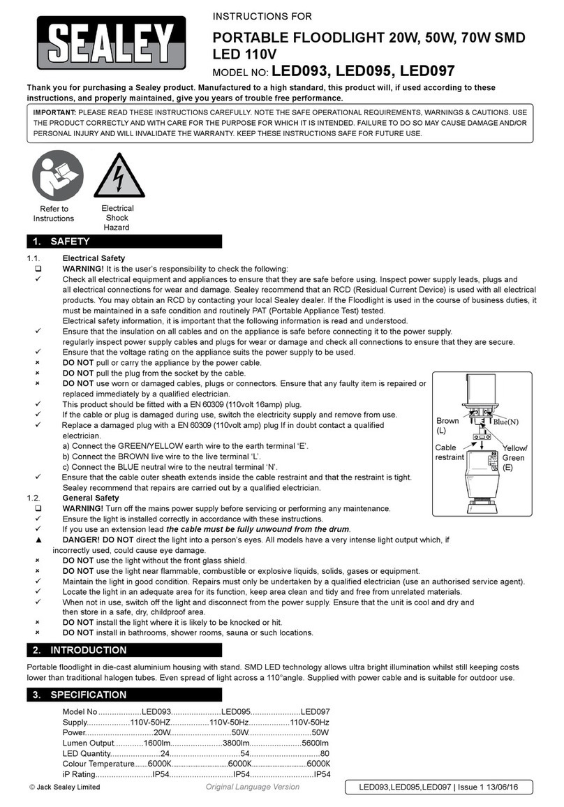
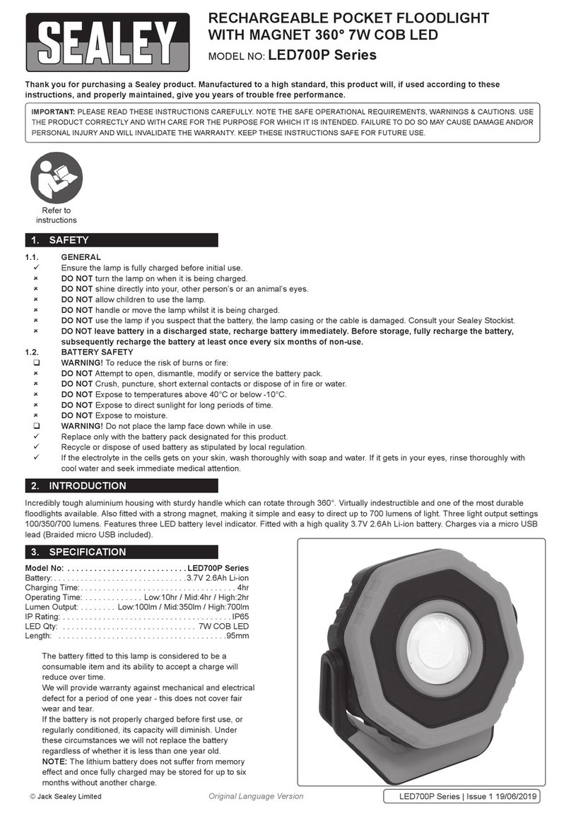
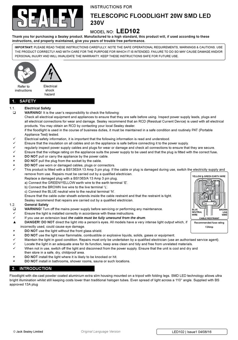
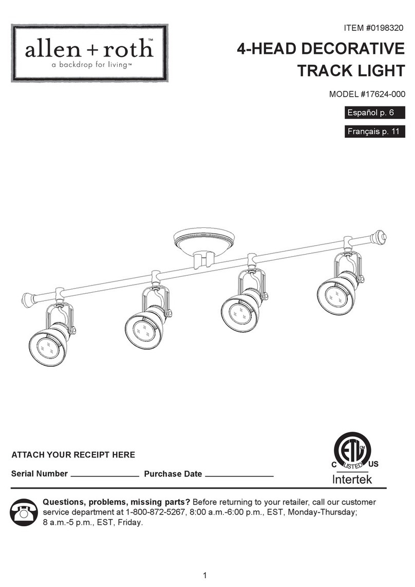
Sealey MD520C.V2 User manual

INSTRUCTIONS FOR:
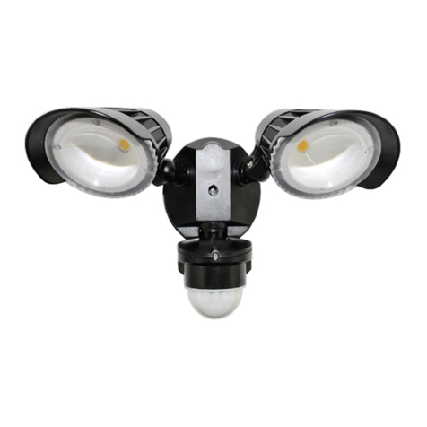
TUNGSTEN/HALOGEN FLOODLIGHT WITH
WALL BRACKET & PIR SENSOR 400W/230V
MODEL No: MD520C.V2
Thank you for purchasing a Sealey product. Manufactured to a
high standard this product will, if used according to these instructions and properly maintained, give you years of trouble free performance.
IMPORTANT: PLEASE READ THESE INSTRUCTIONS CAREFULLY. NOTE THE SAFE OPERATIONAL REQUIREMENTS, WARNINGS, AND
CAUTIONS. USE THIS PRODUCT CORRECTLY, AND WITH CARE FOR THE PURPOSE FOR WHICH IT IS INTENDED. FAILURE TO DO SO
MAY CAUSE DAMAGE, OR PERSONAL INJURY, AND WILL INVALIDATE THE WARRANTY.
1. SAFETY INSTRUCTIONS
4. INSTALLATION INSTRUCTIONS
2. INTRODUCTION
3. SPECIFICATION
fig 1.
fig 2.
Original Language Version MD520C.V2 Issue: 1 - 07/01/11
1.2. GENERAL SAFETY.
WARNING! Turn off the mains power supply before changing
tubes, servicing or performing any maintenance.
Maintain the light in good condition (Repairs must only be undertaken
by a qualified electrician).
Replace or repair damaged parts. Use genuine parts only, non
authorised parts may be dangerous and will invalidate the warranty.
Ensure the light is installed correctly in accordance with these
instructions.
Only install the light on a vertical surface. DO NOT fix the light on any
horizontal surface i.e. ceiling, or overhang.
Light becomes very hot. Installation must be away from flammable or
combustible materials such as wood, cloth, paper etc.
DANGER! DO NOT direct the light into a persons eyes. This unit
has a very intensive light output, which if incorrectly used could
cause eye damage.
DO NOT install the light where it is likely to be knocked or hit.
DO NOT install in bathrooms, shower rooms, sauna or such locations.
DO NOT install near an exhaust outlet. i.e. Boiler flue, dryer outlet, etc.
DO NOT touch the light when operating, allow to cool before touching,
light operates at high temperature.
DO NOT handle halogen bulbs as the natural oil from your fingers and
hands will shorten the bulb life. Handle only with a soft cloth.
DO NOT use the light without the front glass shield. Avoid touching the
glass shield as handling may reduce its serviceable life and cause the
glass to crack.
DO NOT use the light near flammable, combustible or explosive
liquids, solids, gases or equipment.
Specifications:
Power: .....................................................................................................230Volt.
Bulb: ................................................................400Watt Tungsten/Halogen tube.
Detection Angle:..................................................................... 120° (Fan shape).
Detection Range:.....................................................................12m (Adjustable).
Time Delay: .............................................6 seconds to 20 minutes (Adjustable).
Light Sensitivity: .................................................................. 30 Lux (Adjustable).
Replacement Tube: ..............................................................................ML400B.
1.1. ELECTRICAL.
WARNING! It is the user’s responsibility to read, understand and
comply with the following:
WARNING! THIS PRODUCT MUST BE INSTALLED BY A QUALIFIED
ELECTRICIAN.
You must check all electrical equipment and appliances to ensure they
are safe before using. You must inspect power supply leads, plugs and
all electrical connections for wear and damage. You must ensure the risk
of electric shock is minimised by the installation of appropriate safety
devices. An RCCB (Residual Current Circuit Breaker) should be
incorporated in the main distribution board. You must also read and
understand the following instructions concerning electrical safety.
1.1.1. Ensure the light is connected to an appropriate electrical on/off switch.
1.1.2. Ensure the insulation on all cables and the product itself is safe before
connecting to the mains power supply.
1.1.3. Ensure that cables are always protected against short circuit and
overload.
1.1.4. Regularly inspect power supply, leads, plugs and all electrical
connections for wear and damage, especially power connections, to
ensure that none are loose.
1.1.5. Important: Ensure the voltage marked on the product is the same as
the electrical power supply to be used.
1.1.6. DO NOT pull power cable once installed.
1.1.7. DO NOT pull power plugs from sockets by the power cable.
1.1.8. DO NOT use worn or damaged leads, plugs or connections.
Immediately replace or have repaired by a qualified Electrician.
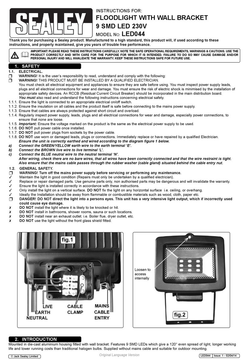
Ensure the unit is correctly earthed and wired according to the
diagram figure 1 below.
a) Connect the GREEN/YELLOW earth wire to the earth terminal ‘E’.
b) Connect the BROWN live wire to live terminal ‘L’.
c) Connect the BLUE neutral wire to the neutral terminal ‘N’.
After wiring, check there are no bare wires, that all wires have been
correctly connected and that the wire restraint is tight.
Infrared detector unit automatically switches 400Watt tungsten/halogen lamp on
when approached by vehicles or persons. Detects movement and heat and is
fitted with adjustable sensitivity and light duration controls. Supplied with wall
mounting bracket and full operating instructions. Supplied without mains cable
and suitable for outdoor mounting.
WARNING! DO NOT connect unit to the mains power supply
before installation. When ready, the lamp must only be connected
to the mains by a qualified electrician.
4.1. Fitting
Give careful consideration to the position of unit to ensure you obtain
maximum benefit from the lighting range, and that an appropriate
electrical power source can be provided.
4.1.1 DO NOT install near an exhaust outlet. i.e. Boiler flue, dryer outlet, etc
as variance in temperature will effect the sensitivity of light. The light
must be mounted on a vertical surface only i.e. on a wall etc.
DO NOT mount on a horizontal surface i.e. ceiling or an overhang,
DO NOT mount so that the face of the lamp is pointing upwards, or is
facing towards the mounting surface. An approximate appropriate
mounting height from the ground is 2.5m.
4.1.2 To protect surfaces and objects from the light’s heat, fix at following
minimum distances between light and any surface/object, (fig 2A).
500mm minimum between the top of the light and any overhead
surface, or objects, i.e. ceilings, overhangs. 200mm between sides of
light and end or side walls, surface or objects. 2 metres minimum
between the front of the light and any object to be illuminated.
Fix the light to vertical surface with appropriate fixings. Do not tilt the
light back beyond 30° (fig 2B) or forward more than 45° (fig 2C).
4.2. Sensor
The sensor may be angled independently of the light. Mounted at
approximately 2.5m above the ground the sensor will have approx 12m
range(g3)witha120ºspread(g4)
4.2.1 The sensor range can be reduced or optically adapted to local
conditions by adjusting the sensor angle accordingly.
4.2.2 Further adjustment may be made by tuning the three switches located
ontheundersideofthesensorasfollows:(refertogure5).
Switch 1. Sensitivity. The sensor range will vary with temperature and
factors such as passing cars, shade from large trees etc. During cold
weather the sensor range will be greater than when hot in summer
temperatures. For example during hot weather the forward detection
range could fall from 12 to 6m and as such the sensor should be
checked and adjusted. Note: the sensitivity factor is far greater when
anobjectpassesacrossthedetectionarea(g4.A)thanwhenanobject
approaches towards the detector (B).
Switch 2. Time adjuster: To adjust the amount of time the light will stay
on when activated. Minimum is 6 seconds, maximum is 20 minutes.
Switch 3. Daylight adjustment: To adjust the sensor to come on in
accordance with the diminishing daylight. From 0 to 30 LUX.
fig 3.
fig 4.
fig 5.
fig 6.
WARNING! Ensure the light is disconnected from the mains power
supply before attempting any of the following.
4.3. BULB CHANGING.
WARNING! Disconnect the light from the mains power supply and allow
the light to cool before attempting to touch the unit.
DO NOT touch the new halogen bulb as the natural oil from your
fingers will shorten the bulb life. Handle with a dry, clean cloth only.
4.3.1. Loosen the screw on the top of the front cover (fig 6.A) and undo,
allowing the front cover to open. Check to ensure the screw is retained
in the front cover tab (3) by the washer.
4.3.2. Remove the old bulb and discard. Hold the new bulb in a clean cloth
and insert it accordingly. (Always use the correct rated bulb fig 6.1).
4.3.3. Check that the weather seal is correctly located in the light’s rim (4) and
the washer is on the securing s crew and close the front cover. Seal by
tightening the securing screw.
4.4. GENERAL
Use only original Sealey parts for repair or replacement of parts.
Repairs must only be undertaken by a qualified electrician.
4.4.1 Clean the light with a dry, dust-free cloth. DO NOT use solvents, or
abrasives to clean the light.
4.4.2 Avoid touching the glass shield (fig 6.2) as handling may reduce its
serviceable life and cause the glass to crack. If necessary clean the
shield (when cold) with alcohol and a soft cloth. If the glass is damaged,
replace it immediately. Use genuine Sealey replacement glass DO
NOT use other glass, and DO NOT use the light without the glass
shield.
4.4.3 Although weather proof the light must not be stored wet. Should the unit
become wet, unplug from mains, wipe dry and store accordingly.
DO NOT use the light without the weather seals intact.
NOTE: It is our policy to continually improve products and as such we reserve the right to alter data, specifications and component parts without prior notice.
IMPORTANT: No liability is accepted for incorrect use of this product.
WARRANTY: Guarantee is 12 months from purchase date, proof of which will be required for any claim.
INFORMATION: For a copy of our latest catalogue and promotions call us on 01284 757525 and leave your full name and address, including postcode.
01284 757500
01284 703534
sales@sealey.co.uk
Sole UK Distributor, Sealey Group,
Kempson Way, Suffolk Business Park,
Bury St. Edmunds, Suffolk,
IP32 7AR
www.sealey.co.uk
Web
email
Original Language Version MD520C.V2 Issue: 1 - 07/01/11
ENVIRONMENTAL PROTECTION.
Recycle unwanted materials instead of disposing of them as waste. All tools, accessories and packaging
should be sorted, taken to a recycle centre and disposed of in a manner which is compatible with the environment.
When the product is no longer required, it must be disposed of in an environmentally protective way.
Parts support is available for this product. To obtain a parts listing and/or diagram, please log on to
www.sealey.co.uk, email sales@sealey.co.uk or phone 01284 757500.

EC DECLARATION
OF CONFORMITY
We the sole importers into the UK, hereby declare that the equipment described below
Description and Function:...............................................................................................................................................
Model/Type:.....................................................................................................................................................................
Manufacturing Date / Serial number (optional).................................................................................................................
Manufacturer's authorised representative within the EC: Jack Sealey Ltd. Kempson Way, Suffolk Business Park,
Bury St. Edmunds, Suffolk, IP32 7AR
Conforms to the requirements of the following Directives, as indicated.
2006/42/EC Machinery Directive 2000/14/EC Outdoor Noise Emissions Directive
2006/95/EC Low Voltage Directive 2002/96/EC WEEE Directive
2004/108/EC EMC Directive 2002/95/EC RoHS Directive
93/68/EEC CE Marking Directive 97/23/EC Pressure Equipment Directive
And the following harmonised standard(s):…………………………………………………..................................................
……………………………………………………………………………………………….......................................................
Additional technical standards and specifications (if applicable):………………………………............................................
……………………………………………………………………………………………….......................................................
Technical file compiled by: Jack Sealey Ltd.
Signed:……………………………………..
Date:………………………………............. Place: Bury St.Edmunds.
Name:…………………………………………
Position:…………………………………....
Being the responsible person appointed by the manufacturer.
Tungsten/Halogen Floodlight with Wall Bracket & PIR Sensor 500W/230V
MD520C.V2
BS EN 60598 part 1; 2008 BS EN 60598 part 2-5: 1998
BS EN 55015: 2006 = A1: 2009 BS EN 61000 part 6-3: 2007
13-Dec-2010
Steve Buckle
Marketing Director
Table of contents
Other Sealey Floodlight manuals

Sealey
Sealey LED086 User manual

Sealey
Sealey LED3000 User manual

Sealey
Sealey LED16S User manual

Sealey
Sealey LED066 User manual

Sealey
Sealey LED098 User manual

Sealey
Sealey LEDFL20W User manual

Sealey
Sealey LED102 User manual

Sealey
Sealey LED112PIR User manual

Sealey
Sealey LED103 User manual

Sealey
Sealey LED170 User manual

Sealey
Sealey ML300C.V3 User manual

Sealey
Sealey LED130T.V2 User manual

Sealey
Sealey LED044S User manual

Sealey
Sealey LED111C User manual

Sealey
Sealey LED30WDL User manual

Sealey
Sealey LED50WL User manual

Sealey
Sealey LED045S User manual

Sealey
Sealey ML500X.V3 User manual

Sealey
Sealey LEDFL15WS User manual

Sealey
Sealey MLF500 User manual