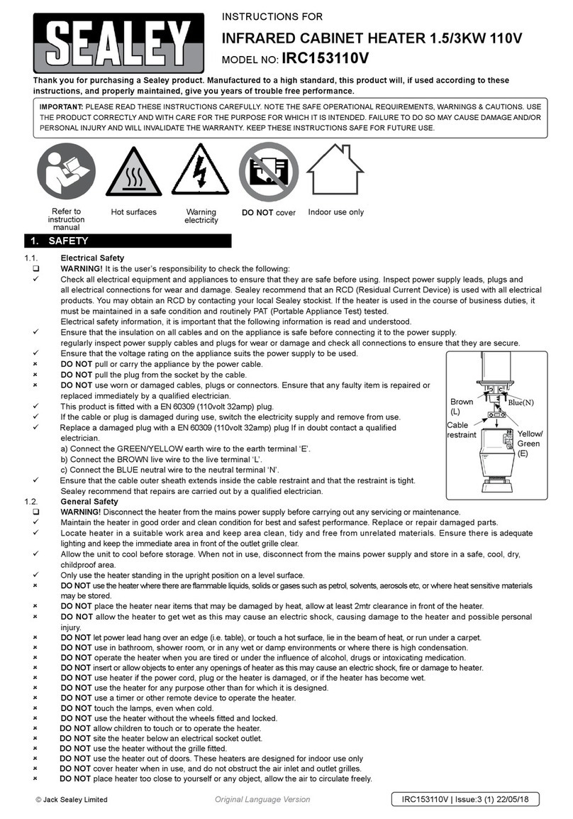
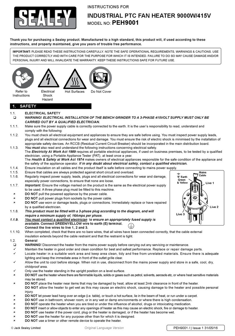
Sealey IRC153.V2 User manual

1. SAFETY INSTRUCTIONS
IMPORTANT: PLEASE READ THESE INSTRUCTIONS CAREFULLY. NOTE THE SAFE OPERATIONAL REQUIREMENTS, WARNINGS & CAUTIONS.
USE THE PRODUCT CORRECTLY AND WITH CARE FOR THE PURPOSE FOR WHICH IT IS INTENDED. FAILURE TO DO SO MAY CAUSE
DAMAGE AND/OR PERSONAL INJURY AND WILL INVALIDATE THE WARRANTY. PLEASE KEEP INSTRUCTIONS SAFE FOR FUTURE USE.
Thank you for purchasing a Sealey product. Manufactured to a high
standard this product will, if used according to these instructions
and properly maintained, give you years of trouble free performance.
INSTRUCTIONS FOR:
INFRA-RED
SPACE WARMERS
1.1. ELECTRICAL SAFETY
p WARNING! It is the responsibility of the owner and the operator to read, understand and comply with the following:
You must check all electrical products, before use, to ensure that they are safe. You must inspect power cables, plugs, sockets and any other connectors for wear
or damage. You must ensure that the risk of electric shock is minimised by the installation of appropriate safety devices. A Residual Current Circuit Breaker (RCCB)
should be incorporated in the main distribution board. We also recommend that a Residual Current Device (RCD) is used. It is particularly important to use an RCD
with portable products that are plugged into a supply which is not protected by an RCCB. If in any doubt consult a qualified electrician. You may obtain a Residual
Current Device by contacting your Sealey dealer.
You must also read and understand the following instructions concerning electrical safety.
1.1.1. The Electricity at Work Act 1989 requires all portable electrical appliances, if used on business
premises, to be tested by a qualified electrician, using a Portable Appliance Tester (PAT),
at least once a year.
1.1.2. The Health & Safety at Work Act 1974 makes owners of electrical appliances responsible for the
safe condition of those appliances and the safety of the appliance operators. If in any doubt
about electrical safety, contact a qualified electrician.
1.1.3. Ensure that the insulation on all cables and on the appliance is safe before connecting it to the
power supply. See 1.1.1. and 1.1.2. and use a Portable Appliance Tester.
1.1.4. Ensure that cables are always protected against short circuit and overload.
1.1.5. Regularly inspect power supply cables and plugs for wear or damage and check all
connections to ensure that none is loose.
1.1.6. Important: Ensure that the voltage marked on the appliance matches the power supply
to be used and that the plug is fitted with the correct fuse - see fuse rating at right.
1.1.7. DO NOT pull or carry the appliance by the power cable.
1.1.8. DO NOT pull the plug from the socket by the cable.
1.1.9. DO NOT use worn or damaged cables, plugs or connectors. Immediately have any faulty
item repaired or replaced by a qualified electrician. When an ASTA/BS approved UK
3 pin plug is damaged, cut the cable just above the plug and dispose of the plug safely.
Fit a new plug according to the following instructions (UK only).
a) Connect the GREEN/YELLOW earth wire to the earth terminal E.
b) Connect the BROWN live wire to the live terminal L.
c) Connect the BLUE neutral wire to the neutral terminal N.
d) After wiring, check that there are no bare wires, that all wires have been correctly
connected, that the cable outer insulation extends beyond the cable restraint and that the
restraint is tight.
Double insulated products, which are always marked with this symbol , are fitted with live
(brown) and neutral (blue) wires only. To rewire, connect the wires as indicated above - DO
NOT connect either wire to the earth terminal.
1.1.10. If an extension reel is used it should be fully unwound before connection. A reel with an RCD
fitted is preferred since any appliance plugged into it will be protected. The cable core section is
important and should be at least 1.5mm2, but to be absolutely sure that the capacity of the reel is
suitable for this product and for others which may be used in the other output sockets, we
recommend the use of 2.5mm2section cable.
Blue
Neutral
Wire
Yellow & Green
Earth Wire
Cable
Restraint
Brown
Live
Wire
IRC153.V2, IRC153.110V, IRS153.V2, IRS153.110V - 1 - 010704
230V models: FUSE RATING 13 AMP
1.1.11 ROUND PIN PLUG FOR 110V MODELS.
1.1.12. Supply: 110Vac 1ph protected by a 32 amp delayed fuse or equivalent breaker.
1.1.13. Replace a damaged plug according to the following instructions (see 110V plug diagram at right).
Ensure the unit is correctly earthed via a three-pin 110V 32 amp plug to suit supply.
a) Connect the green/yellow earth wire to the earth terminal .
b) Connect the brown live wire to the live terminal L.
c) Connect the blue neutral wire to the neutral terminal, unmarked.
d) After wiring, check that there are no bare wires, that all wires have been correctly
connected, that the cable outer insulation extends past the cable
restraint and that the restraint is tight.
pWARNING! Reminder, the electrical installation of the heater must only be carried out by a
qualified electrician. Make sure that power supply cable is correctly earthed.
230V MODELS
110V MODELS
110V models: FUSE RATING 32 AMP
MODELS:
IRC153.V2 IRC153.110V IRS153.V2 IRS 153.110V
1.2 GENERAL SAFETY
pWARNING! These heaters use Light Technology, whereby quartz infrared elements heat objects by emitting energy at a level similar to the heat of the
sun. Any objects in the line of sight of the elements will start to feel warm, the air in between is not heated. Traditional methods heat the air and rely
on air circulation to transfer heat. As a result, quartz halogen heating can project heat over longer distances.
pWARNING! Disconnect the heater from the mains power supply before carrying out any servicing or maintenance.
3Disconnect the heater from the power supply before handling or cleaning.
3Maintain the heater in good order and clean condition for best and safest performance.
3Maintain the cabinet in good condition. Replace or repair damaged parts. Use genuine parts only. Unauthorised parts may be dangerous and will
invalidate the warranty.
3Locate heater in a suitable work area and keep area clean, tidy and free from unrelated materials. Ensure there is adequate lighting and keep
the immediate area in front of the outlet grill clean.
3Only use the heater standing in the upright position on a level surface.

7DO NOT touch the quartz lamps, even when cold.
7DO NOT use the heater without the guards fitted.
7DO NOT use the heater without the wheels fitted and locked.
7DO NOT allow the heater to get wet as this may cause an electric shock, causing damage to the heater and possible personal injury.
7DO NOT let power lead hang over an edge (i.e. table), or touch a hot surface, lie in the beam of heat, or run under a carpet.
7DO NOT cover heater when in use, and do not obstruct the air inlet and outlet grilles.
7DO NOT use in bathroom, shower room, or in any wet or damp environments or where there is high condensation.
7DO NOT operate the heater when you are tired or under the influence of alcohol, drugs or intoxicating medication.
7DO NOT insert or allow objects to enter any openings of heater as this may cause an electric shock, fire or damage to heater.
7DO NOT use the heater out of doors. These heaters are designed for indoor use only.
7DO NOT use heater if the power cord, plug or the heater is damaged, or if the heater has become wet.
7DO NOT use the heater where there are flammable liquids, solids or gases such as petrol, solvents, aerosols etc, or where heat sensitive materials may be stored.
7DO NOT place the heater near items that may be damaged by heat, allow at least 2mtr clearance in front of the heater.
7DO NOT touch the outlet grille of the heater during and immediately after use as it will be hot.
7DO NOT allow children to touch or to operate the heater.
7DO NOT place heater too close to yourself or any object, allow the air to circulate freely.
7DO NOT use the heater for any purpose other than for which it is designed.
3Allow the unit to cool before storage. When not in use, disconnect from the mains power supply and store in a safe, cool, dry, childproof area.
3.3. IRS153.V2 - Fig.2.
3.3.1. Fit the handle section of the
support frame to the wheel
section ensuring the fixing
holes align.
3.3.2. Fit the heater to the support
frame using the bolts provided,
ensuring the shaped spacers are
fitted either side of the frame as
shown. Tighten the bolts
sufficiently to retain the heater at
the required angle.
3.3.3 Remove the front grille by
unscrewing the retaining screws.
3.3.4 Remove the side reflectors by
unscrewing the retaining screws.
3.3.5 Extract the lamps from the
shipping carton. NEVER TOUCH
LAMP GLASS DIRECTLY WITH
FINGERS, ONLY TOUCH THE
CERAMIC EDGES OR USE A
SOFT CLOTH, OTHERWISE
LAMPS COULD BE DAMAGED!
3.3.6 Carefully insert each lamp into the two push-in side fittings with a gentle
pressure.
3.3.7 Check the lamps are properly locked.
3.3.8 Reassemble side reflectors and front guard.
3.4. IRS153.110V - Fig.2.
3.4.1. Fit the handle section of the support frame to the wheel section
ensuring the fixing holes align.
3.4.2. Fit the heater to the support frame using the bolts provided, ensuring the
shaped spacers are fitted either side of the frame as shown. Tighten the bolts
sufficiently to retain the heater at the required angle.
3.4.3. Remove the front grille retaining screws and remove the protective
packing fitted between the lamps and the reflectors.
3.4.4. Refit the front grille using the four retaining screws.
3.1. IRC153.V2 - Fig.1.
3.1.1. Attach the wheel sub-assemblies to
the base of the heater using the
bolts provided ensuring the
lockable wheels are to the rear of
the heater.
3.1.2. Attach the handle to the top of the
heater using the bolts
provided, ensuring the shaped
spacers are fitted between the
heater and the handle as shown.
3.1.3 Remove the front grille by
unscrewing the retaining screws.
3.1.4 Remove the side reflectors by
unscrewing the retaining screws.
3.1.5 Extract the lamps from the
shipping carton. NEVER
TOUCH LAMP GLASS
DIRECTLY WITH FINGERS,
ONLY TOUCH THE CERAMIC
EDGES OR USE A SOFT
CLOTH, OTHERWISE LAMPS
COULD BE DAMAGED!
3.1.6 Carefully insert each lamp into the two push-in side fittings with a
gentle pressure.
3.1.7 Check the lamps are properly locked.
3.1.8 Reassemble side reflectors and front guard
3.2. IRC153.110V - Fig.1.
3.2.1. Attach the wheel sub-assemblies to the base of the heater using the bolts
provided ensuring the lockable wheels are to the rear of the heater.
3.2.2. Attach the handle to the top of the heater using the bolts provided,
ensuring the shaped spacers are fitted between the heater and the handle
as shown.
3.2.3. Remove the front grille retaining screws and remove the
protective packing fitted between the lamps and the reflectors.
3.2.4. Refit the front grille using the four retaining screws.
3. ASSEMBLY
Fig 1 Fig 2
4. HEATER OPERATION
4.1. Operating the heater.
4.1.1. Place the heater on a level floor in a suitable position in the area you require to heat. Allow a minimum of 2mtr between the heater and adjacent objects.
4.1.2. Plug the heater into the mains supply.
4.1.3. Select the required output by using the two rocker switches (on the side of the IRC153 & IRC153.110V and on the back of the IRS153 & IRS153.110V)
which switch the lamps on and off. Each lamp has an output of 1500W.
4.1.4. To switch the unit off, select 0 on both the rocker switches and unplug from the mains. Allow the unit to cool before handling or storage.
pWARNING! DO NOT touch the top of the heater when in use as it becomes hot.
p
p
WARNING! Always allow elements to cool before moving the units. Use only on a smooth even surface. Failure to do so will cause premature wear to
the elements and reduce their working life.
2.1. Introduction
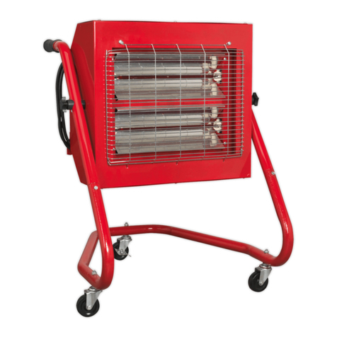
2.1.1. Powder coated metal cabinet with 2 quartz infra-red elements and chemically polished reflectors for maximum heat emission. Controllable power output by
rocker switches on the side/back of the cabinet. Features easy-rolling swivel castors with 2 locking castors. Suitable for wide range of personnel warming
and restorative applications. Supplied with cable and BS/ASTA approved plug.
2.2. Specification
Models . . . . . . . . . . . . . . . . . . . . . . . . . . . . .IRC153.V2 . . . . . . . . . . . . . .IRC153.110V . . . . . . . . . . . . . . . .IRS153.V2 . . . . . . . . . . . . . .IRS153.110V
Power output (2 heat settings) . . . . . .TOTAL 3000 Watt . . . . . . . . . .TOTAL 3000 Watt . . . . . . . . . .TOTAL 3000 Watt . . . . . . . . . .TOTAL 3000 Watt
Size W X D X H . . . . . . . . . . . . . .530 x 560 x 960mm . . . . . . . . .530 x 560 x 960mm . . . . . . . . .610 x 680 x 850mm . . . . . . . .610 x 680 x 850mm
Weight . . . . . . . . . . . . . . . . . . . . . . . . . . . . . . . . .18Kg . . . . . . . . . . . . . . . . . . . .18Kg . . . . . . . . . . . . . . . . . . . .13Kg . . . . . . . . . . . . . . . . . . . .13Kg
Voltage . . . . . . . . . . . . . . . . . . . . . . . . . . .230V (50Hz) . . . . . . . . . . . . . .110V (50Hz) . . . . . . . . . . . . . .230V (50Hz) . . . . . . . . . . . . . .110V (50Hz)
2. INTRODUCTION AND SPECIFICATIONS
IRC153.V2, IRC153.110V, IRS153.V2, IRS153.110V - 1 - 010704
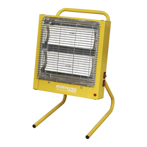
IRC153.V2 & IRC153.110V
IRS153.V2 & IRS153.110V
5. MAINTENANCE
pWARNING! Before attempting any maintenance ensure the unit is unplugged from the mains power supply, that it is cool and it is on level ground.
7DO NOT touch the lamp glass, even when cold.
7DO NOT use the heater without the guards fitted.
5.1 Cleaning.
5.1.1. To clean the reflector, remove the guard by unscrewing the retaining screws and wipe the reflector with a clean dry cloth. DO NOT use abrasives or
solvents. The surface of the reflector is very soft and scratches may cause it to overheat. Replace the guard.
5.2. Changing a lamp (110V models).
pWARNING! Lamps should only be changed by a qualified electrician.
5.2.1. Remove the front grille by unscrewing the retaining screws.
5.2.2. Remove the side reflectors by unscrewing the retaining screws.
5.2.3. Ease the spring clips on the ends of the lamp and pull the lamp forward such that it clears the edge of the clips but is still retained in the clips.
5.2.4. Remove the back panel of the unit by unscrewing the retaining screws.
Note: The back panel of the IRC153 provides rigidity when fitted. Removal of the back panel renders the heater unstable.
5.2.5. Disconnect the lamp supply leads from the switch inside the heater.
5.2.6. Remove the lamp from the spring clips.
5.2.7. Fitting the new lamp is the reverse of paragraphs 5.2.1. to 5.2.6. NEVER TOUCH THE LAMP GLASS DIRECTLY WITH FINGERS, ONLY TOUCH THE
CERAMIC EDGES OR USE A SOFT CLOTH, OTHERWISE THE LAMP COULD BE DAMAGED!
Changing a lamp (230V models).
5.2.8. Remove the front grille by unscrewing the retaining screws.
5.2.9. Remove the side reflectors by unscrewing the retaining screws.
5.2.10. Carefully extract the lamp from side fittings.
5.2.11. Extract the new lamp form the shipping carton. NEVER TOUCH THE LAMP GLASS DIRECTLY WITH FINGERS, ONLY TOUCH THE CERAMIC EDGES
OR USE A SOFT CLOTH, OTHERWISE THE LAMP COULD BE DAMAGED!
5.2.12. Carefully insert the lamp into the two push-in side fittings with a gentle pressure.
5.2.13. Check the lamp is properly locked.
5.2.14. Reassemble side reflectors and front guard.
Declaration of Conformity We, the sole importer into the UK, declare that the products listed here are in conformity with the following standards and directives.
The construction files for these products are held by the Manufacturer and may be inspected, by a national authority,
upon request to Jack Sealey Ltd.
For Jack Sealey Ltd. Sole importer into the UK of Sealey Power Products.
INFRA-RED SPACE WARMERS
Models: IRC153.V2, IRC153.110V,
IRS153.V2 & IRS153.110V
73/23/EEC Low Voltage Directive
89/336/EEC EMC Directive
1st July 2004
Signed by Mark Sweetman
NOTE: It is our policy to continually improve products and as such we reserve the right to alter data, specifications and component parts without prior notice.
IMPORTANT: No liability is accepted for incorrect use of product.
WARRANTY: Guarantee is 12 months from purchase date, proof of which will be required for any claim.
INFORMATION: For a copy of our latest catalogue and promotions call us on 01284 757525 and leave your full name and address, including postcode.
01284 757500
01284 703534 sales@sealey.co.uk
Sole UK Distributor
Sealey Group,
Bury St. Edmunds, Suffolk.
www.sealey.co.uk
Web
email
IRC153.V2, IRC153.110V, IRS153.V2, IRS153.110V - 1 - 010704
This manual suits for next models
3
Table of contents
Other Sealey Heater manuals

Sealey
Sealey LP1500.V2 User manual

Sealey
Sealey CH28110V User manual

Sealey
Sealey DEH2001.V2 User manual

Sealey
Sealey CH2800S User manual

Sealey
Sealey Space Warmer LP100.V5 User manual

Sealey
Sealey PEH3001 User manual

Sealey
Sealey AB100E User manual

Sealey
Sealey ir20.v2 User manual

Sealey
Sealey IR15110V User manual

Sealey
Sealey IR18 User manual

Sealey
Sealey IR40 User manual

Sealey
Sealey IRC153110V User manual

Sealey
Sealey LP35 User manual

Sealey
Sealey EH30001 User manual

Sealey
Sealey CH2800 User manual

Sealey
Sealey CD2005T.V2 User manual

Sealey
Sealey IWMH2003RC User manual

Sealey
Sealey EH5001 User manual

Sealey
Sealey IWMH2003RC.V2 User manual

Sealey
Sealey CH2800.V2 User manual