Sealey AB100E User manual

INSTRUCTIONS FOR:
SPACE WARMER PARAFFIN /
KEROSENE / DIESEL HEATER
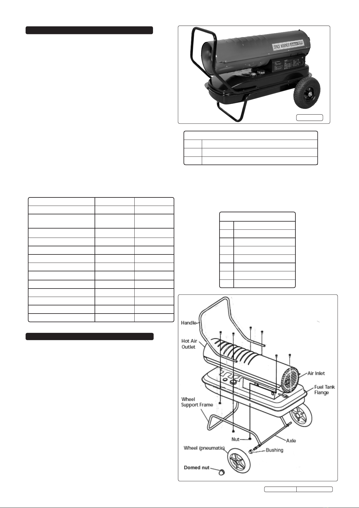
MODEL No's: AB70E, AB100E
Thank you for purchasing a Sealey product. Manufactured to a high standard this product will, if used according to these instructions and properly
maintained, give you years of trouble free performance.
1. SAFETY INSTRUCTIONS
IMPORTANT: PLEASE READ THESE INSTRUCTIONS CAREFULLY. NOTE THE SAFE OPERATIONAL REQUIREMENTS, WARNINGS AND CAUTIONS.
USE THE PRODUCT CORRECTLY AND WITH CARE FOR THE PURPOSE FOR WHICH IT IS INTENDED. FAILURE TO DO SO MAY CAUSE DAMAGE
AND/OR PERSONAL INJURY AND WILL INVALIDATE THE WARRANTY. PLEASE KEEP INSTRUCTIONS SAFE FOR FUTURE USE.
1.2. GENERAL SAFETY
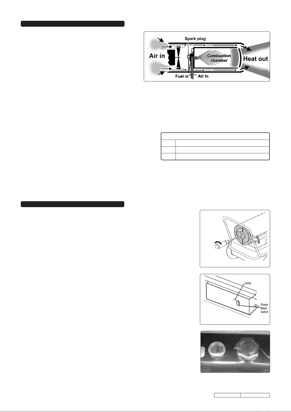
DANGER! Risk of carbon monoxide poisoning. Failure to provide proper ventilation could result in serious illness or death.
Check that the heater is in sound condition and good working order. Take immediate action to repair or replace damaged parts.
Use recommended parts only. Unapproved parts may be dangerous and will invalidate the warranty.
WARNING! Only use paraffin, kerosene or diesel to fuel your heater, in accordance with instructions contained in this manual.
WARNING! Keep spare fuel in suitable containers and away from sources of heat or ignition.
Keep the front of the heater a minimum of 2.5 metres from any combustible materials (i.e. wooden items, cloth, plastics, paper, etc).
Only operate on a level and stable surface.
WARNING! DO NOT use the heater near flammable material, liquids, solids, gases or compressed gas cylinders.
DO NOT use the heater in closed rooms, living areas, basements or below ground level.
DO NOT allow untrained persons to operate the heater and DO NOT operate the heater without the cover.
DO NOT move or handle the heater when hot.
DO NOT leave the heater unattended when in use. Switch the heater off and unplug from the mains before leaving work area.
DO NOT fill the fuel tank whilst the heater is running or still hot.
DO NOT over-fill the fuel container. Wipe up any spilt fuel immediately.
DO NOT obstruct the air inlet (rear) and air outlet (front) of the heater.
DO NOT use any form of duct work in front or at the rear of the heater.
DO NOT allow children or animals near the heater when in use, or while hot.
WARNING! RISK OF ELECTRIC SHOCK. DO NOT expose the heater to water spray, rain, dripping water or wind.
DO NOT operate the heater when you are tired or under the influence of alcohol, drugs or intoxicating medication.
DO NOT touch the heater outlet or dome when first switched off as these are very hot and will take time to cool.
Ensure that the heater is correctly turned off when not in use and store in a safe, dry area, out of reach of children.
DO NOT unplug the heater to switch it off. Use the ON/OFF switch.
NOTE: This appliance is not intended for persons (including children) with reduced physical, sensory or mental capabilities, or lack of
experience and knowledge, unless they have been given supervision or instruction concerning use of the appliance by a person
responsible for their safety.Children should be supervised to ensure that they do not play with the appliance.
WARNING! Improper maintenance can lead to poor combustion and soot production.
1.1. ELECTRICAL SAFETY
WARNING! It is the responsibility of the owner and the operator to read, understand and comply with the following:
You must check all electrical products, before use, to ensure that they are safe. You must inspect power cables, plugs, sockets and any other
connectors for wear or damage. You must ensure that the risk of electric shock is minimised by the installation of appropriate safety devices. A
Residual Current Circuit Breaker (RCCB) should be incorporated in the main distribution board. We also recommend that a Residual Current
Device (RCD) is used. It is particularly important to use an RCD with portable products that are plugged into a supply which is not protected
by an RCCB. If in any doubt consult a qualified electrician. You may obtain a Residual Current Device by contacting your Sealey dealer.
You must also read and understand the following instructions concerning electrical safety:
1.1.1. The Electricity at Work Act 1989 requires all portable electrical appliances, if used on business premises, to be tested by a qualified
electrician, using a Portable Appliance Tester (PAT), at least once a year.
1.1.2. The Health & Safety at Work Act 1974 makes owners of electrical appliances responsible for the safe condition of those appliances
and the safety of the appliance operators. If in any doubt about electrical safety, contact a qualified electrician.
1.1.3. Ensure that the insulation on all cables and on the appliance is safe before connecting it to the power supply. See 1.1.1. and 1.1.2.
and use a Portable Appliance Tester.
1.1.4. Ensure that cables are always protected against short circuit and overload.
1.1.5. Regularly inspect power supply cables and plugs for wear or damage and check all
connections to ensure that none are loose.
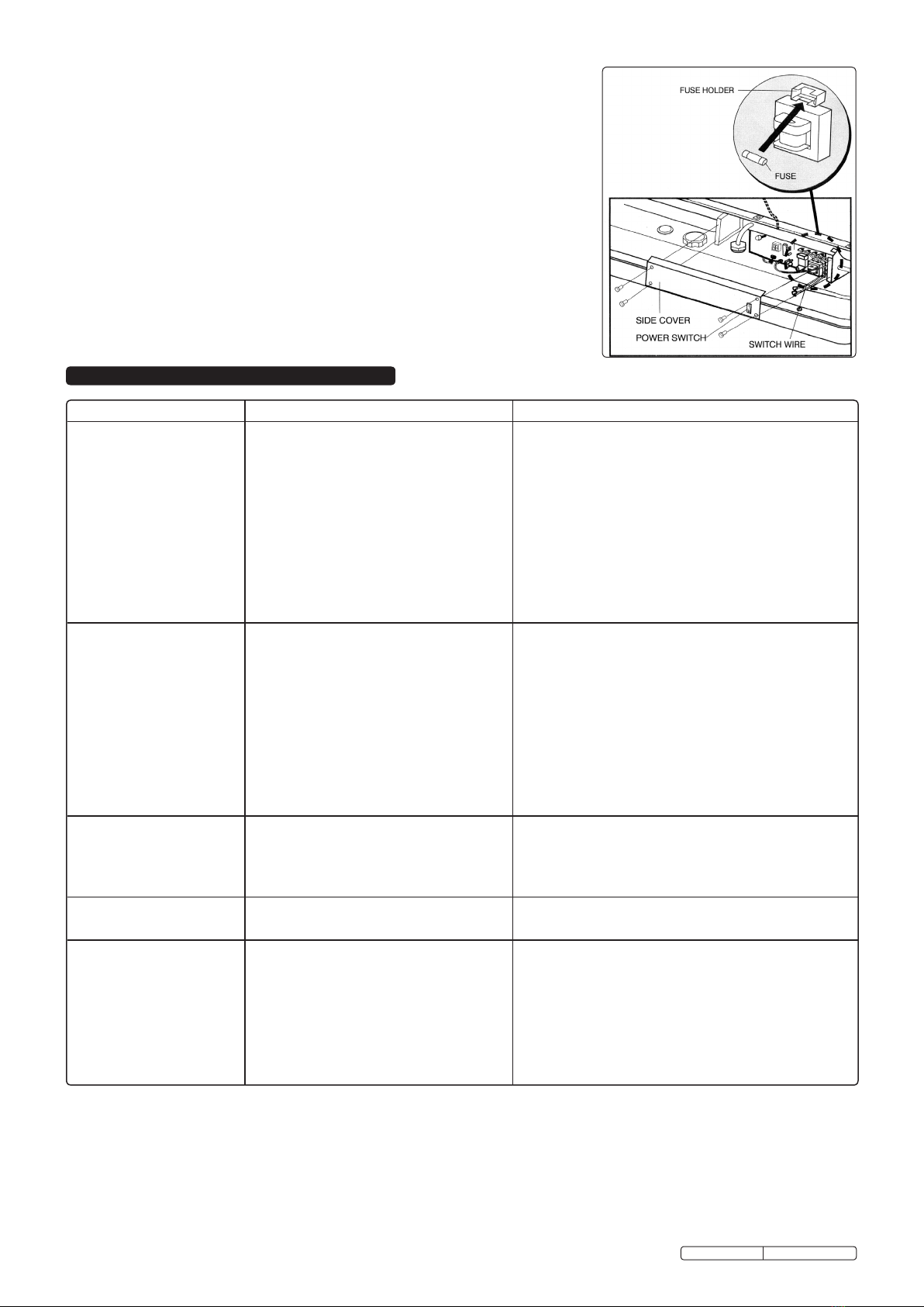
1.1.6. IMPORTANT! Ensure that the voltage marked on the appliance matches the power supply
to be used and that the plug is fitted with the correct fuse - see fuse rating at right.
1.1.7. DO NOT pull or carry the appliance by the power cable.
1.1.8. DO NOT pull the plug from the socket by the cable.
1.1.9. DO NOT use worn or damaged cables, plugs or connectors. Immediately have any faulty
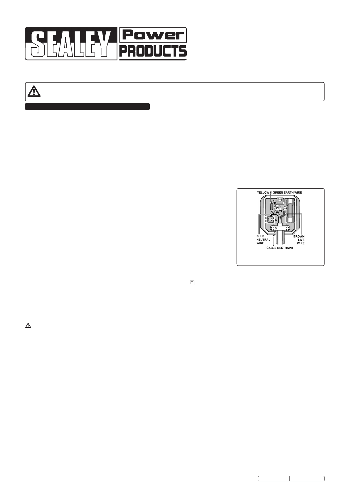
item repaired or replaced by a qualified electrician. When an ASTA/BS approved UK
3 pin plug is damaged, cut the cable just above the plug and dispose of the plug safely.
Fit a new plug according to the following instructions (UK only).
a) Connect the GREEN/YELLOW earth wire to the earth terminal ‘E’.
b) Connect the BROWN live wire to the live terminal ‘L’.
c) Connect the BLUE neutral wire to the neutral terminal ‘N’.
d) After wiring, check that there are no bare wires, that all wires have been correctly connected, that the cable outer
insulation extends beyond the cable restraint and that the restraint is tight.
Double insulated products, which are always marked with this symbol , are fitted with live (brown) and neutral (blue) wires only.
To rewire, connect the wires as indicated above - DO NOT connect either wire to the earth terminal.
1.1.10. If an extension reel is used it should be fully unwound before connection. A reel with an RCD fitted is preferred since any appliance
plugged into it will be protected. The cable core section is important and should be at least 1.5mm², but to be absolutely sure that the
capacity of the reel is suitable for this product and for others which may be used in the other output sockets, we recommend the use
of 2.5mm² section cable.
RECOMMENDED
FUSE RATING: 5AMP
AB70E, AB100E Issue: 1 - 05/04/12
Original Language Version

Our range of paraffin/kerosene/diesel heaters represents excellent
value. Workshop tried and tested. Proven pump systems handle
paraffin, kerosene or diesel with only minor adjustment of air
compressor. Both models are fitted with heavy-duty pneumatic
wheels and a heavy-duty filler cap.
Sealey Advantages
• PARAFFIN, KEROSENE OR DIESEL - These Sealey AB heaters
will operate on all.
• CLEAN BURNING - A specially designed burner head in a
stainless steel combustion chamber ensures a more thorough
burn of fuel which means greater fuel economy and maximum
heating effect.
• FILTER PROTECTION - The compressor unit is protected by
extra large filter elements.
• LARGE FUEL TANK - These AB series heaters will operate for
between 9 and 11 hours on a single fill of fuel.
• SAFETY FEATURES - The AB series heaters are fitted with a
flame-out device which cuts the fuel supply when the flame is
inadvertently extinguished.
• QUALITY - Manufactured to comply with rigorous standards.
• AFTER SALES SERVICE - The best after sales service in the
business. Full spares back up for all models.
2. INTRODUCTION & SPECIFICATIONS
3. ASSEMBLY
Unpack the heater and check the contents. Should there be
any damaged or missing parts, contact your Sealey Dealer
immediately.
3.1. Slide axle through wheel support frame, slide a bushing onto
each end of the axle.
3.2. Install wheels with valve stem on the outside. Thread a domed
nut onto each end of the axle and tighten.
3.3. Place heater on wheel support frame, ensuring that the air
inlet is by the wheels and line up the holes on the fuel tank
flange with those on the wheel support frame.
3.4. Place handle on fuel tank flange and line up with the wheel
support frame fixing holes. Insert 2 bolts through the middle
fuel tank flange hole and both frames and secure finger tight
only with nuts and washers.
3.5. Insert 2 bolts through the fuel tank flange and wheel support
frame and secure finger tight with nuts and washers.
3.6. Insert 2 bolts through the fuel tank flange and the handle
and secure finger tight with nuts and washers.
3.7. When assembly is complete, securely tighten all nuts.
WARNING! DO NOT use the heater without the support
frame fully assembled.
Model AB70E AB100E
Rating BTU/hr (kW) 70000 (20.5) 100000 (29.3)
Fuel
Parafn/
Kerosene/Diesel
Parafn/
Kerosene/Diesel
Fuel Tank Capacity (Litres) 19 38
Fuel Consumption (Ltr/hr) 2.0 3.5
Maximum Running Time 9 11
Pump Pressure (PSI) +/-10% 3.7 4.5
Voltage/Amp 230V/5A 230V/5A
Air Flow (cfm) 240 520
Heated Area (m3) 385 566
Phase Single Single
Power Cable (m) 2.1 2.1
Size (cm) 99 x 58.5 x 66 99 x 58.5 x 66
Net Weight (Kg) 15.3 24.5
fig.1
Assembly Parts
1 Wheel Support Frame
1 Axle
2 Wheels
1 Handle
2 Axle Bushings
2 Domed Nuts
6 Frame Bolts
6 Frame Nuts and Washers
WARNING!This heater is not suitable for use with Bio-Diesel; use of
Bio-Diesel will damage the lter and seals.
Damage caused by use of Bio-Diesel will not be covered by warranty.
Minimum Clearances from Combustibles
Top 1.2m
Sides 1.2m
Front 2.4m
AB70E, AB100E Issue: 1 - 05/04/12
Original Language Version
AB100E

4.1. Principles of heat generation.
When the heater is switched on, the air compressor draws in
air, pressurises it and passes it through an air line to the
burner head nozzle. The air flow causes fuel to be drawn from
the tank. The fuel and air mix is then sprayed into the
combustion chamber. The mixture is automatically ignited by
the spark plug and a high temperature heat stream is
generated in the combustion chamber. Air is drawn into the
unit by a fan and is pushed around the cool chamber situated
between combustion chamber and outer casing. This fast
flowing air sucks the heat stream out of the combustion
chamber, providing the required heat. The heat output is
governed by the compressor - the higher the air pressure the hotter the flame.
If the system malfunctions, a “flame-out” control will operate and automatically cut off the motor and fuel supply. Should this happen,
switch off machine and unplug from mains supply. Refer to trouble shooting chart in Section 8 and/or return unit to supplier for
maintenance.
4.2. Fuel.
The AB series will operate with three types of fuel - paraffin, kerosene or diesel. The following information must be understood before
use.
4.2.1. Paraffin / Kerosene will sometimes cause condensation. If the unit is stored unused (i.e. during the summer) such condensation will
cause the fuel tank to corrode and, when next used, the flame to pulsate due to water in the tank. To overcome the problem, the fuel
must be drained off, if the heater is to be unused for long periods.
4.3. When used in the construction or agricultural industries ensure that
the safety regulations in force are adhered to with regard to distances
from flammable materials and any other specified substances.
WARNING! Air contaminants taken into the heater may affect the
heat output, damage the unit and may cause health problems.
Example: Bodyshop filler dust or paint overspray will damage the
motor bearing, clog the filter and compressor and contaminate
the combustion chamber causing flame flutter and health hazards.
Please note that any parts damaged by filler dust or overspray will not be covered by warranty.
4.4. VENTILATION. Minimum recommended opening for fresh air intake, AB70E = 0.21m²,AB100E = 0.30m².
WARNING! Only use the heater in well ventilated areas. Careful consideration must be given to the placing of the heater to provide
safe and comfortable heating. Ensure continuous ventilation is provided to the heater operating area, allow at least 0.01m2/kW heater
output. A ventilation opening must run to the outside of the premises in which the heater is to be operated.
4. OPERATING CONDITIONS
fig.2
5. OPERATING INSTRUCTIONS
fig.3 Pump Pressure Adjustment
fig.4 Control Panel
fig.5 Fuel Gauge and Filler
5.1. Running the heater on paraffin / kerosene.
The heater has been pre-set at the factory to a setting which is suitable for paraffin,
kerosene or diesel, and will produce the correct heat output when first used from new. You
should run the heater at the pre-set output in order to ensure the long life, safety and
reliability of the unit.
WARNING! The first time the heater is used, run it up outdoors and run for at least 10
minutes to burn off any oils used in the manufacturing process.
5.1.1. Ensure that the unit is unplugged from the mains supply.
5.1.2. Fill the fuel tank (fig.5) with paraffin, kerosene or diesel until the fuel gauge points to "F".
DO NOT mix the fuels, always drain and clean out the fuel tank when changing type of fuel.
WARNING! Never refill the fuel tank indoors, always refill outside. DO NOT over-fill. Wipe
away any spillage before use.
5.1.3. Plug into the mains power supply.
5.1.4. Press the power switch to the "ON" position. The lamp will illuminate and the heater will start.
NOTE: The electrical components of this heater are protected by a fuse mounted on the PCB. If the
heater fails to fire, check this fuse first and replace it if necessary. Also check the power
source to ensure that the proper voltage is being provided to the heater.
5.1.5. The pump pressure should be +/- 10% of the pressure stated in the specification table
above, if the unit is running outside of this tolerance, adjust the pressure as shown in fig.3.
5.2. Shut down the heater using the ON/OFF switch and then disconnect from the mains supply.
NEVER SHUT DOWN THE HEATER BY PULLING OUT THE PLUG.
DO NOT touch the heater outlet as this will remain hot for some time.
5.3. Restarting the heater.
5.3.1. Wait at least 10 seconds after turning the heater "OFF".
5.3.2. Push the Power switch to "ON".
WARNING! Ensure that all pre-starting precautions are carried out.
5.4. Monitoring the heat output.
5.4.1. If, after a period of time, the heat output begins to fall, this indicates that either the unit
requires maintenance, as laid out in Section 6, or that the environmental conditions the unit
is operating in are not correct, see Section 4.
DO NOT ATTEMPT TO TURN UP THE AIR PRESSURE TO COMPENSATE FOR HEAT
LOSS as this could result in damage to the combustion chamber and will invalidate the
warranty.
Minimum Clearances from Combustibles
Top 1.2m
Sides 1.2m
Front 2.4m
AB70E, AB100E Issue: 1 - 05/04/12
Original Language Version

6. MAINTENANCE
Looking after your AB heater will pay dividends, ensuring heat, as and when you need it
and avoiding frustrating operational problems.
IMPORTANT! We strongly recommend that you arrange for heater servicing during
the summer months to avoid being left without heat during the winter.
WARNING! Unplug unit from mains power supply before opening or servicing heater.
See Section 1 regarding electrical safety and maintenance.
6.1. General. Keep the heater clean; wipe outer case with a damp, clean cloth. Do not use
abrasives. Oil wheels if necessary. Check heater for damage and immediately repair or
replace with authorised parts. Contact your Sealey Service Agent.
6.2. Fuel Tank.
6.2.1. For long term storage the fuel tank will need to be drained. The tank should be flushed
every 200 hours of operation or as required. There is a drain plug on the underside of the
fuel tank (fig.6). To remove the plug pull down the plug grip and remove the seal head from
the drain hole. Drain the fuel into a suitable container. Using a small amount of fresh
paraffin, rinse and swirl the paraffin inside the tank and then drain fully.
6.2.2. Replace the seal head back into the drain hole and push the plug grip into the seal head to
lock into position (fig.7).
6.3. Spark plug (electrode). Clean and check the plug gap every 600 hours, or replace if
necessary. Clean the spark plug using a wire brush and set the gap to 3.5mm (fig.8).
6.4. Air filter. The cast alloy compressor unit is protected by a three stage filter system (fig.9).
The intake filter should be cleaned every 500 hours, or more regularly if the appliance is
used in a dusty environment.
6.4.1. Remove the fan guard and the filter end cover.
6.4.2. Take out the intake filter, wash it using a light detergent and dry it thoroughly.
6.4.3. The Output and Lint filters should be replaced every 500 hours, or less if the operating
conditions demand.
6.5. Fuel filter. The fuel filter (fig.10) should be cleaned twice per season, unless contamination
occurs where it will require cleaning immediately. To clean the filter, remove and wash in
paraffin.
6.6. Nozzle. The nozzle should be cleaned or replaced at least once per heating season.
6.6.1. To clean dirt from nozzle, unscrew the four retaining screws and hinge open the top cover
of the heater.
6.6.2. Remove the burner head and remove the nozzle (fig.11).
6.6.3. Blow compressed air through the front of the nozzle. For stubborn dirt, it is advisable to
soak the nozzle in clean paraffin to help loosen any particulates.
6.6.4. Refit nozzle and burner head in reverse order to above.
6.7. Flame-out device. The AB heaters are fitted with a flame-out device (a photocell, see
fig.12), which cuts the fuel supply should the flame be inadvertently extinguished, or if the
unit overheats. If this happens, switch off the heater and unplug from the mains supply.
Check the heater to determine the fault. In particular check that the air intake is not
obstructed and that the internal fan is rotating freely. Wait a few minutes and restart the
unit. If the problem persists contact your local Sealey Service Agent.
6.8. Fan. Fan blades (fig.13) should be cleaned at least once per heating season (depending
on environment). Remove the outer case and clean the fan blades with a damp cloth.
Dry fan thoroughly using compressed air.
WARNING! MAINTENANCE MUST ONLY BE UNDERTAKEN BY A QUALIFIED PERSON.
WE STRONGLY RECOMMEND THAT ALL SERVICING IS DONE BY YOUR LOCAL
SERVICE AGENT.
fig.8 Spark Plug Replacement
fig.7 Drain Plug Replacement
3.5mm
fig.6 Drain Plug Removal
fig.9 Air Filter Replacement
fig.10 Fuel Filter
fig.11 Nozzle Replacement
fig.12 Photocell Position
fig.13 Fan Replacement
AB70E, AB100E Issue: 1 - 05/04/12
Original Language Version

6.9. Fuse Replacement
NOTE: This is a fuse protected heater.
If the heater fails to ignite, check the fuse as shown in fig.14, before contacting your
local service agent.
WARNING! Unplug the heater from the mains power supply before attempting any
maintenance work.
6.9.1. Remove the control panel screws and lift off the side panel to reveal the printed circuit
board.
6.9.2. Disconnect switch wires from the power switch.
6.9.3. Remove fuse from holder as shown.
6.9.4. Replace fuse with one of the same specification and rating.
WARNING! DO NOT substitute the fuse with one of a higher or lower rating as this
may result in a fire hazard.
6.9.5. Reconnect switch wires to the power switch.
6.9.6. Replace side panel.
fig.14 Fuse Replacement
AB70E, AB100E Issue: 1 - 05/04/12
Original Language Version
Problem Possible Cause Solution
Heater res, but main
PCB shuts heater off after
a short period of time.
Lamp is ickering.
1. Incorrect pump pressure. 1. Adjust pump pressure (see g.3).
2. Dirty input, output or lint lter. 2. Clean/replace Air Filter.
3. Dirty fuel lter. 3. Clean/replace Fuel Filter.
4. Nozzle is dirty. 4. Clean/replace Nozzle.
5. Photocell lens is dirty. 5. Clean/replace Photocell.
6. Photocell not installed properly. 6. Adjust Photocell position.
7. Photocell defective. 7. Replace Photocell.
8. Improper electrical connection between
main PCB and photocell.
9. Ambient temperature too low for fuel type,
8. Check wiring connections.
9.Change fuel type.
Heater will not operate or
motor runs for a short time.
Lamp ickers.
1. No fuel in fuel tank. 1. Fill tank with fresh fuel.
2. Incorrect pump pressure. 2. Adjust pump pressure (see g.3).
3. Corroded spark plug or incorrect gap. 3. Clean/adjust/replace spark plug.
4. Dirty fuel lter. 4. Clean/replace fuel lter.
5. Dirty nozzle. 5. Clean/replace nozzle.
6. Moisture in fuel/fuel tank. 6. Rinse out fuel tank with fresh fuel.
7. Faulty electrical connection. 7. Inspect all electrical connections.
8. Ignitor wire not connected to spark plug. 8. Re-attach ignitor wire to spark plug.
9. Defective ignitor. 9. Replace ignitor.
Fan does not operate when
heater is plugged in and
Power Switch is in the “ON”
position. The lamp is ickering
or on.
1. Broken electrical connection between main
PCB and motor.
1. Inspect all electrical connections.
Poor combustion. 1. Flames extending beyond heater. 1. Decrease pump pressure (see g.3).
2. Low heat output. 2. Increase pump pressure (see g.3).
Heater does not turn on and
the lamp is not lit.
1. Temperature limit sensor has overheated. 1. Push power switch to “OFF” and allow heater to cool for
10 minutes. Push power switch to “ON”.
2. No electrical power. 2. Check power cable and extension cable connections. Test
power supply.
3. Fuse blown on PCB. 3. Check/replace fuse (see g.14).
4. Faulty connection between temperature limit
sensor and PCB.
4. Inspect all electrical connections.
WARNING! This heater is not suitable for use with Bio-Diesel; use of Bio-Diesel will damage the lter and seals.
Damage caused by use of Bio-Diesel will not be covered by warranty.
7. TROUBLESHOOTING

Parts support is available for this product. To obtain a parts listing and/or diagram, please log on to www.sealey.co.uk, email
sales@sealey.co.uk or phone 01284 757500.
NOTE: It is our policy to continually improve products and as such we reserve the right to alter data, specifications and component parts without prior notice.
IMPORTANT: No liability is accepted for incorrect use of this product.
WARRANTY: Guarantee is 12 months from purchase date, proof of which will be required for any claim.
INFORMATION: For a copy of our latest catalogue and promotions call us on 01284 757525 and leave your full name and address, including postcode.
01284 757500
01284 703534
sales@sealey.co.uk
Sole UK Distributor, Sealey Group,
Kempson Way, Suffolk Business Park,
Bury St. Edmunds, Suffolk,
IP32 7AR
www.sealey.co.uk
Web
email
AB70E, AB100E Issue: 1 - 05/04/12
Original Language Version
Although these heaters operate with diesel fuel, when the temperature is
below 0°C, diesel additives are required to maintain the diesel's viscosity.
Typically diesel can cloud in freezing conditions and will start to gel.
You will need additives for your fuel in these conditions.
Kerosene/Paraffin does not start to gel until the ambient temperature is
around -40°C.
Environmental Protection.
Recycle unwanted materials instead of disposing of them as waste. All tools, accessories and packaging
should be sorted, taken to a recycle centre and disposed of in a manner which is compatible with the environment.
When the product is no longer required, it must be disposed of in an environmentally protective way.
AB70E Wiring Diagram
AB100E Wiring Diagram
This manual suits for next models
1
Table of contents
Other Sealey Heater manuals

Sealey
Sealey IRH800W User manual

Sealey
Sealey FH2010 User manual

Sealey
Sealey IWMH2003RC User manual

Sealey
Sealey CD2005 User manual

Sealey
Sealey IR37.V4 User manual

Sealey
Sealey CH30 User manual

Sealey
Sealey PEH3001.V2 User manual

Sealey
Sealey IWMH2000R.V2 User manual

Sealey
Sealey FH2009.V2 User manual

Sealey
Sealey CH2800 User manual

Sealey
Sealey AB2050 User manual

Sealey
Sealey CH30110VS User manual

Sealey
Sealey CH2800.V2 User manual

Sealey
Sealey CD2005TT User manual

Sealey
Sealey AB Series User manual

Sealey
Sealey LP40S User manual

Sealey
Sealey IR13.V2 User manual

Sealey
Sealey CH30110V User manual

Sealey
Sealey LP13.V3 User manual

Sealey
Sealey VS260 User manual