4.1. ASSEMBLING THE CASTOR BASE
4.1.1. Referring to fig.1, take one wheel beam (35) and attach a non-locking castor
(34) to the short wheel mounting plate using a locking washer (33) and nut
(32).
4.1.2. Attach a locking castor (36) to the long wheel mounting plate using a locking
washer (33) and nut (32). Attach the castors to the other wheel beam (35).
4.1.3. Take the supporting beam (41) and mount a wheel beam at either end of it
as shown below. Drop the ‘U’ channels at either end of the supporting beam
down over each wheel beam. Align the holes in the wheel beams with the
holes in the supporting beam and insert two bolts (37) at either side. Retain
the four bolts by attaching four nuts (6). Assembling the pump/column to the
castor base.
4.1.4. The pre-assembled pump and column unit is fixed to the supporting beam
using three pairs of fixings, two pairs in the horizontal plane and one pair in
the vertical plane.
4.1.5. Referring to fig.2, take the pre-assembled pump and column unit and slide it
onto the main support beam and up against the vertical plate welded to the
support beam. Align the holes in the pump block with the holes in the vertical
plate. Slide a spring washer (39) onto each socket cap bolt (26) and insert the
bolts through the plate and screw them finger tight into the pump block.
4.1.6. Slide a washer onto each long bolt (28) and insert the bolts horizontally
through the column bracket and all the way through the main support beam.
Secure the bolts finger tight only at this stage using using two spring washers
(39) and two nuts (25).
4.1.7. Slide a washer onto each long bolt (31) and insert the bolts vertically from
underneath, through the corners of the column bracket and all the way
through the main support beam. Secure the bolts on the top surface of the
beam using two spring washers (39) and two nuts.
4.1.8. Now progressively tighten all three pairs of fixings checking that the pump/
column remains vertical.
4.2. ASSEMBLING THE ROLLER SUPPORT
4.2.1. Referring to fig.3, take the roller support assembly and bolt it to the angled
plate at the base of the column using four socket cap bolts (20).
4.2.2. There are two mounting positions for the right hand roller. Choose the position
to suit the job in hand.
4.3. ASSEMBLING THE BRIDGE JOINT
4.3.1. Referring to fig.3, take the bridge joint (2) and push it onto the end of the
hydraulic ram so that channel walls lie either side of the lifting rod.
4.3.2. Slide the washer (4) onto the bolt (3) and insert the bolt through the channel
and through the lifting rod. Secure the bolt with a spring washer (5) and nut
(6). Insert the thumb screw (1) into the collar of the bridge joint and tighten
it.
4.4. ASSEMBLING THE SLIDE BAR AND SAFETY BAR
4.4.1. Referring to fig.3, take the safety rod (13) and insert the slide bar (14) into and
through the collar at the top of the safety bar. Insert the threaded end of the
slide bar into slider tube (10). Move the assembly up the lifting rod and lock it
in the required place by turning the knob at the end of the slide bar clockwise
until it is tight. Insert the wing bolt (12) into the safety rod collar. Move the
safety rod along the slide bar to the required position and tighten the wing nut.
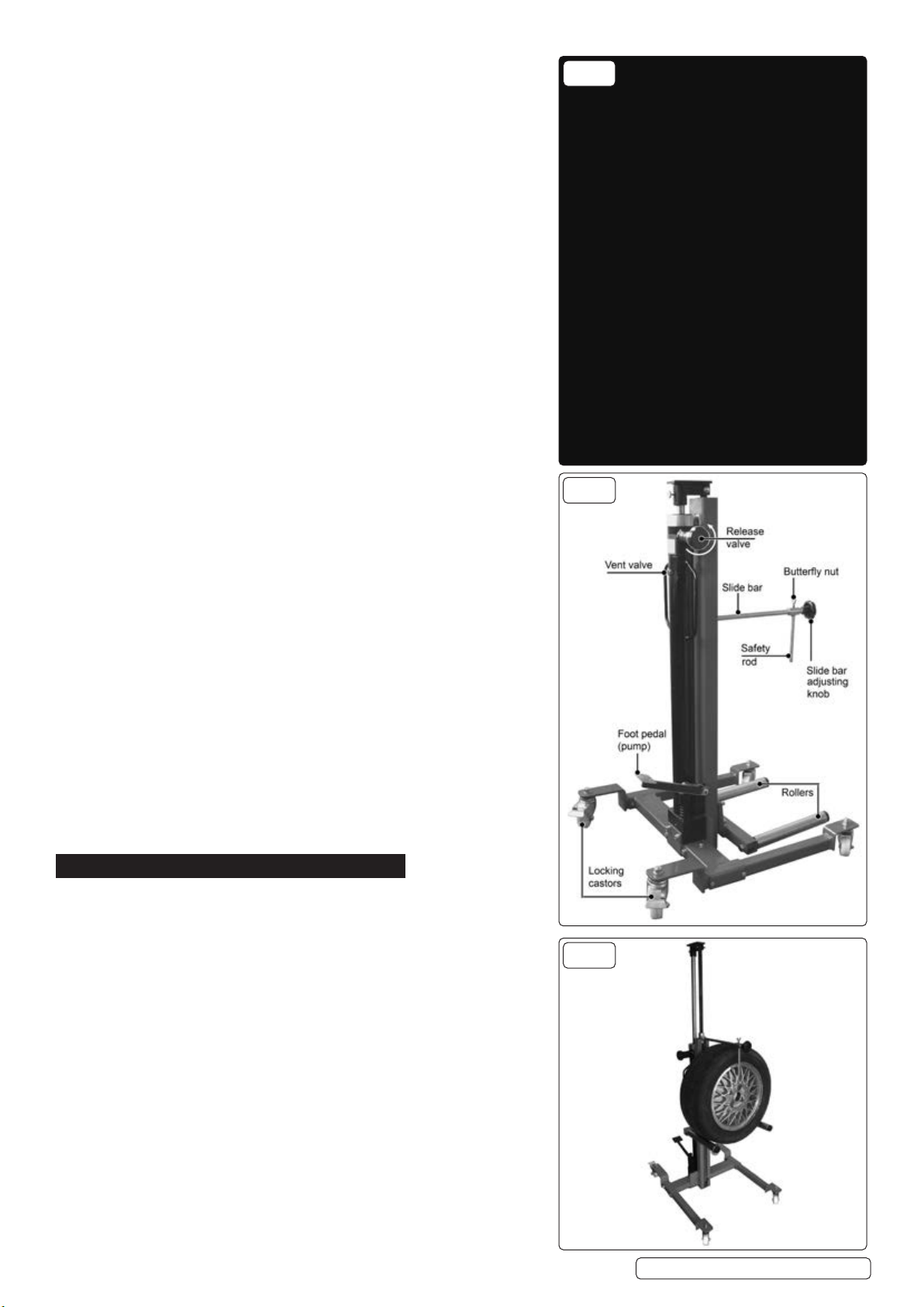
5. OPERATION
5.1. Remove the transit plug at the back of the hydraulic unit between the handles
and replace it with the vent valve supplied. See fig.4.
5.2. Set the position of the right hand roller to suit the size of wheel to be removed
/ installed. See fig.3.
5.3. LIFTING - Raise the roller assembly by pumping the foot pedal up and down
through its full stroke until it reaches the correct height. Centre the trolley
around the wheel, as close in as possible. When the wheel has been released
from the vehicle and is resting on the rollers move the trolley out from the
vehicle and adjust the slide bar and safety rod to retain the wheel before
lowering it. See fig.5.
5.4. LOWERING - The release valve is spring loaded shut. The speed of lowering
is dependent on how far you open the valve. Turn the valve anti-clockwise,
against spring load, for controlled lowering of the roller assembly.
5.5. TRANSPORTATION - Before moving a laden trolley ensure that the wheel
is centred on the rollers and adjust the slide bar and safety rod to retain the
wheel. Ensure that the roller assembly is fully lowered before moving a wheel.
Original Language Version
© Jack Sealey Limited WD80 Issue 6 (H, 2, 3) 19/10/23
FIG.3
FIG.4
FIG.5


