manuals.online logo
Brands
  1. Home
  2. •
  3. Brands
  4. •
  5. Sealey
  6. •
  7. Lifting System
  8. •
  9. Sealey MC401 User manual

Sealey MC401 User manual

Unpack the lift and check contents with list below. Should there be any damaged or missing parts contact your supplier immediately.
Content
 Main Assembly  Sliding Plate  Leading Plate  Vice
 Lifting Pedal  Release Pedal  Pedal Guard  Bolts, Washers, Nuts, Cotter Pins
p
p
WARNING! Keep your hands away from moving parts.
Numbers in brackets refer to item numbers in the parts diagram.
3.1. Assembly
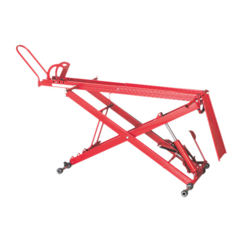
3.1.1. Fit the sliding plate (66) to the platform (60), to cover the rear wheel removal aperture.
3.1.2. Attach leading plate (69) to end of platform (60) using washers (49) and cotter pins (70).
3.1.3. Fit the front wheel vice assembly (64) to the front of the platform (60) using bolts (65),
washers (49) and nuts (33).
3.1.4. Insert the lift foot pedal (71) into the pump piston spindle (10) and insert the
release foot pedal (72) into the release valve spindle (5).
3.1.5. Attach the guard plate (67) to the frame (44A) using bolts (68) and nuts (P23). This guard covers the release foot pedal to minimise the
risk of accidental lowering.
3.1.6. An extension plate (77) is provided for longer wheelbase bikes. Attach this to the front end of the main platform using the screws (75)
and the nuts (76).
3.2. Before first use
3.2.1. Leave the pump for one hour, to allow the oil to settle, before purging the system.
Note: Failure to allow sufficient time for the oil to settle could result in air remaining in the oil. In this event, the pump will not purge
completely first time and a second purge will be required.
3.2.2. Purge the hydraulic circuit, to eliminate any air in the system, by fully pressing the release valve pedal (72) and pumping the lift pedal
(71) 15 to 20 times.
3.2.3. Test the lift, unladen, by raising it to full height and then lowering it. Depress release valve pedal (72) slowly to control the rate of descent.
INSTRUCTIONS FOR:
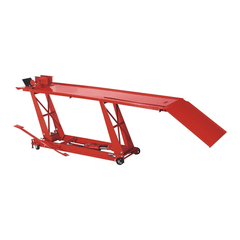
400KG HYDRAULIC MOTORCYCLE LIFT
Model: MC401
Thank you for purchasing a Sealey product. Manufactured to a high standard this product will, if used according to these instructions and properly
maintained, give you years of trouble free performance.
1. SAFETY INSTRUCTIONS
2. SPECIFICATION
3Maintain the lift in good condition (use an authorised service agent).
3Replace or repair damaged parts. Use genuine parts only. Unauthorised parts may be dangerous and will invalidate the warranty.
3Use a qualified person to lubricate and maintain the lift. DO NOT use brake fluid to top up hydraulic unit.
3Locate the lift in a suitable work area. Keep area clean and tidy and free from unrelated materials, and ensure that there is adequate lighting.
3Ensure that the floor is level and strong enough (preferably concrete) to take the weight of the lift and the bike. DO NOT operate the lift on
tarmacadam, as the surface may be unstable.
3Keep the lift clean for best and safest performance.
3Before use, stabilise the lift by turning the foot stops so that the lift is just raised off of its wheels.
3The maximum bike weight is 400kg. DO NOT exceed this rated capacity.
3Remove ill fitting clothing. Remove ties, watches, rings and other loose jewellery, and contain long hair.
3Maintain correct balance and footing, do not over reach. Ensure the floor is not slippery and wear non-slip shoes.
3Ensure the bike is adequately secured to the lifting platform with appropriate straps.
3Before lifting check that there are no overhead obstructions.
3When platform has been raised to the working height ensure that the platform safety spindle is fitted to prevent accidental lowering.
3Keep children and unauthorised persons away from the work area.
3The lowering speed will vary according to the weight of the load and the release valve setting.
7DO NOT use the lift for a task it is not designed to perform.
7DO NOT operate the lift if it is damaged.
7DO NOT exceed the rated capacity of the lift.
7DO NOT operate the lift when you are tired or under the influence of alcohol, drugs or intoxicating medication.
7DO NOT allow untrained persons to operate the lift.
7DO NOT attempt to transport a load on the lift. The lift must only be used in a static position for raising and lowering loads.
7DO NOT make any modifications to the lift and DO NOT adjust or tamper with the safety valve.
3Before lowering the lift ensure that there are no obstructions underneath the platform and that all persons are standing clear.
3Before storing in safe area, ensure that all parts are clean and free of grease and oil. Store lift fully lowered.
IMPORTANT: PLEASE READ THESE INSTRUCTIONS CAREFULLY. NOTE THE SAFE OPERATIONAL REQUIREMENTS, WARNINGS AND CAUTIONS.
USE THE PRODUCT CORRECTLY AND WITH CARE FOR THE PURPOSE FOR WHICH IT IS INTENDED. FAILURE TO DO SO MAY CAUSE
DAMAGE AND/OR PERSONAL INJURY AND WILL INVALIDATE THE WARRANTY. PLEASE KEEP INSTRUCTIONS SAFE FOR FUTURE USE.
3. ASSEMBLY
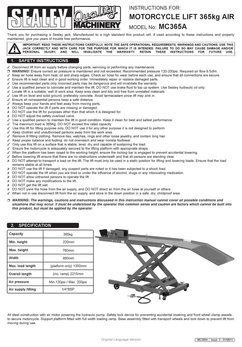
Specification
Capacity . . . . . . . . . . . . . . . . . . . . . .400kg
Minimum Height . . . . . . . . . . . . . . .180mm
Maximum Height . . . . . . . . . . . . . .760mm
MC401 - 5 -130104
p
p
WARNING! Ensure that you read, understand and apply the safety instructions before use.
p
p
WARNING! DO NOT attempt to overload the lift. The hydraulic pump is equipped with safety valve which will prevent an
excessive load from being lifted.
4.1. Position the lift in a suitable area, checking that the surface on which the lift will stand is solid and flat (preferably concrete). Ensure that
the adjusting screws (23A) are screwed down to raise the castor wheels of the ground and thus prevent the lift moving during use.
4.2. Check that the lift is fully lowered, that the vice jaws are open and that the sliding plate is in position.
4.3. Wheel the bike up the leading plate (69) and onto the platform so that the front wheel is just beyond the vice. Support bike on the centre stand.
Note: 1. If rear wheel is to be removed bike must be positioned so that the rear wheel is over the platform aperture.
2.There is a choice of mounting holes for the vice to cater for various sizes of bike.
4.4. Clamp front wheel in vice to prevent any movement of the bike.
4.5. By depressing the lift foot pedal (71), raise the lift.
4.6. When the lift is fully raised pass the set spindle (73) through the holes in the front lifting arm (59) so that the lift cannot be inadvertently lowered.
4.7. When work is complete, check under the lift to ensure that there are no obstructions and that it is safe to lower the unit.
Remove the set spindle from the front lifting arm and then SLOWLY press the release valve pedal (72) to GENTLY lower the lift.
QIMPORTANT: The speed of lowering is controlled by the release valve. The more the valve is opened the more rapidly the lift descends.
Ensure the descent is slow and controlled.
4.8. When the lift is fully lowered, open the vice jaws and remove the bike from the lift.
4. OPERATING INSTRUCTIONS
5.1. When the lift is not in use, it must be stowed in the lowest position to minimise ram and piston corrosion.
5.2. Keep the lift clean and wipe off any oil or grease. Lubricate all moving parts..
5.3. Before each use check all parts. If any part of the lift is damaged or suspect remove lift from service and take necessary action to repair.
DO NOT use the lift if it is believed to have been subjected to abnormal load or shock. Inspect and take appropriate action.
5.4. Periodically check the ram and piston for signs of corrosion. Clean exposed areas with a clean oiled cloth.
5.5. The hydraulic oil level is checked as follows:
1) Remove hydraulic unit from lift and stand upright.
2) Remove vented plug (fig.1.A). Correct oil level is up to plug aperture - add hydraulic oil as necessary.
p WARNING! Only a good quality hydraulic oil, such as SEALEY HYDRAULIC OIL, must be used. DO NOT use brake fluid.
QIMPORTANT: Only fully qualified personnel should attempt maintenance or repair. Contact your authorised dealer.
5. MAINTENANCE
6. DECLARATION OF CONFORMITY
IMPORTANT:NO RESPONSIBILITY IS ACCEPTED FOR INCORRECT USE OF THE LIFT.
Hydraulic products are repaired by local service agents only. We have service/repair agents in all parts of the UK.
DO NOT RETURN THE PRODUCT TO US. Please call us on 01284 757500 to obtain the address and telephone number of your local agent.
If the product is under guarantee please contact your dealer.
De-commissioning
Should the lift become completely unserviceable, draw off the oil into an approved container and dispose of the lift and the oil according to
local regulations.
Declaration of Conformity We, the sole importer into the UK, declare that the product listed here is
in conformity with the following standards and directives.
For Jack Sealey Ltd. Sole importer into the UK of Sealey Quality Machinery.
400KG HYDRAULIC MOTORCYCLE LIFT
Model: MC401
98/37/EC Machinery Directive
93/68/EEC CE Marking Directive 2nd October 2002Signed by Mark Sweetman
The construction file for this product is held by the Manufacturer and may be inspected, by a national
authority, upon request to Jack Sealey Ltd.
NOTE: It is our policy to continually improve products and as such we reserve the right to alter data, specifications and component parts without prior notice.
IMPORTANT: No liability is accepted for incorrect use of this product.
WARRANTY: Guarantee is 12 months from purchase date, proof of which will be required for any claim.
INFORMATION: For a copy of our latest catalogue and promotions call us on 01284 757525 and leave your full name and address, including postcode.
Sole UK Distributor,
Sealey Group, Bury St. Edmunds, Suffolk.
01284 757500 sales@sealey.co.uk
01284 703534 www.sealey.co.uk
e-mail Web
MC401 - 5 -130104
Item Part No. Description
1MC401/001 Hydraulic Pump Asm.
2 MC401/002 Link
3MC401/003 Pin
4MC401/004 Cotter Pin
5MC401/005 Spindle, Release Valve
6 MC401/006 Pin
6-1 MC401/006-1 Clip
7MC401/007 Link
8 MC401/008 Pin
9 MC401/009 Snap Ring C
10 MC401/010 Spindle, Pump Piston
11 MC401/011 Pin
12 MC401/012 Snap Ring C
13A MC401/013A Frame, RH Kit
23A MC401/023A Adjusting Screw Asm.
26A MC401/026A Castor
29 MC401/029 Ball Bearing
32 MC401/032 Nut, M12
33 MC401/033 Nut, M10
34 MC401/034 Front Spindle
35 MC401/035 Spacing Collar
36 MC401/036 Washer
37 MC401/037 Bush, Front Wheel
38 MC401/038 Front Wheel
39 MC401/039 Washer
40 MC401/040 Nut, M20
41 MC401/041 Lifting Arm, Stop Rod
42 MC401/042 Washer
43 MC401/043 Nut, M16
44A MC401/044A Frame, LH Kit
Item Part No. Description
49 MC401/049 Washer
50 MC401/050 Bolt, M10 x 16
51 MC401/051 Return Spring
52 MC401/052 Back Lifting Arm
53 MC401/053 Lifting Arm Spindle
54 MC401/054 Bolt
55 MC401/055 Bush
56 MC401/056 Bolt, M12 x 65
57 MC401/057 Washer
58 MC401/058 Nut, M12
59 MC401/059 Front Lifting Arm
60 MC401/060 Platform
61 MC401/061 Bush
63 MC401/063 Bolt, M12 x 40
64 MC401/064 Vice
65 MC401/065 Bolt, M10 x 25
66 MC401/066 Sliding Plate
67 MC401/067 Guard Plate
68 MC401/068 Bolt, M8 x 20
69 MC401/069 Leading Plate
70 MC401/070 Cotter Pin
71 MC401/071 Foot Pedal, Lift
72 MC401/072 Foot Pedal, Release
73 MC401/073 Set Spindle
74 MC401/074 Spring Washer
P23 MC401/P23 Nut, M8
75 MC401/075 Screw
76 MC401/076 Nut
77 MC401/077 Extension plate
MC401/RK Repair kit
PARTS LIST FOR:
400KG HYDRAULIC MOTORCYCLE LIFT
Model: MC401
Sole UK Distributor,
Sealey Group, Bury St. Edmunds, Suffolk.
Issue: 3
Date Issued: 080104
01284 757500 sales@sealey.co.uk
01284 703534 www.sealey.co.uk
e-mail Web
Test Certificate No.
QCC/07-B
HEALTH AND SAFETY EXECUTIVE
Health & Safety at Work Act 1974. Docks Regulations 1934, regulations 18(a) & 22(a) SR & O 1934 No 279.
Form prescribed by the Secretary of State for
CERTIFICATE OF TEST AND EXAMINATION OF LIFTING DEVICES
AND THEIR ACCESSORY GEAR, BEFORE BEING TAKEN INTO USE
MODEL NUMBER
DESCRIPTION OF LIFTING
DEVICE AND SERIAL NO. (IF ANY)
HYDRAULIC MOTORCYCLE LIFT
MODEL NUMBER: MC401
SERIAL NUMBER:
MINIMUM
LIFTING
HEIGHT
MM
180
MAXIMUM
LOAD
KG
400
PROOF
LOAD
APPLIED
KG
500
MAXIMUM
LIFTING
HEIGHT
MM
760
COMPANY CONDUCTING TEST:
This test was commissioned by Jack Sealey Limited, Kempson Way, Suffolk Business Park, Bury St. Edmunds,
Suffolk, 1P32 7AR and was undertaken by Changshu Tongrun M & E Co. Ltd., the manufacturer of the product
in China and the holder of the construction file. This certificate is signed by the Chief Engineer for the
manufacturer. We hereby certify that the motorcycle lift covered by this test certificate has been tested to 25% overload
and the safety valve has been set at the rated working capacity. This product was manufactured in China and product
liability insurance is in effect within the U.K. through the Axa Insurance Company (policy number available on
request).
ENGINEER CONDUCTING TEST . . . . . . . . . . . . . . . . . . . . . . . . . . .Chief Engineer
Changshu Tongrun M & E Co. Ltd.
China Manufacturer No:...........................
DATE:.................................
Sole UK Distributor,
Sealey Group, Phone: 01284 757500
Bury St Edmunds, Fax: 01284 703534
Suffolk.
ISSUE 3 - 220403

Other Sealey Lifting System manuals

Sealey MCl500 User manual

Sealey

Sealey MCl500 User manual

Sealey ES502.V2 User manual

Sealey

Sealey ES502.V2 User manual

Sealey HPT150.V2 User manual

Sealey

Sealey HPT150.V2 User manual

Sealey MT500 User manual

Sealey

Sealey MT500 User manual

Sealey MC450 User manual

Sealey

Sealey MC450 User manual

Sealey MC365A User manual

Sealey

Sealey MC365A User manual

Sealey DH03.V2 User manual

Sealey

Sealey DH03.V2 User manual

Sealey MC135 User manual

Sealey

Sealey MC135 User manual

Sealey LS501 User manual

Sealey

Sealey LS501 User manual

Sealey MC680A User manual

Sealey

Sealey MC680A User manual

Sealey HPT300 User manual

Sealey

Sealey HPT300 User manual

Sealey MR1 User manual

Sealey

Sealey MR1 User manual

Sealey HPT400H.V2 User manual

Sealey

Sealey HPT400H.V2 User manual

Sealey MC455.V2 User manual

Sealey

Sealey MC455.V2 User manual

Sealey ES502.V2 User manual

Sealey

Sealey ES502.V2 User manual

Sealey MS064 User manual

Sealey

Sealey MS064 User manual

Sealey PPL01 User manual

Sealey

Sealey PPL01 User manual

Sealey MC454E User manual

Sealey

Sealey MC454E User manual

Sealey MC390AH User manual

Sealey

Sealey MC390AH User manual

Sealey MC455 User manual

Sealey

Sealey MC455 User manual

Sealey AK98941 User manual

Sealey

Sealey AK98941 User manual

Sealey MC450.V2 User manual

Sealey

Sealey MC450.V2 User manual

Sealey MC680A User manual

Sealey

Sealey MC680A User manual

Sealey 1250CX User manual

Sealey

Sealey 1250CX User manual

Popular Lifting System manuals by other brands

ServerLIFT SL-350X Operator's manual

ServerLIFT

ServerLIFT SL-350X Operator's manual

Silverline 763620 manual

Silverline

Silverline 763620 manual

STS STP01-DRU01-EX operating instructions

STS

STS STP01-DRU01-EX operating instructions

Youngman BoSS user guide

Youngman

Youngman BoSS user guide

Walker Magnetics NEO-1000 Operation manual

Walker Magnetics

Walker Magnetics NEO-1000 Operation manual

twin busch TW M-02 Installation, operation and maintanance

twin busch

twin busch TW M-02 Installation, operation and maintanance

Aqua Creek Products SPA LIFT ULTRA manual

Aqua Creek Products

Aqua Creek Products SPA LIFT ULTRA manual

Access 7000 installation manual

Access

Access 7000 installation manual

Meganex MEG73 instruction manual

Meganex

Meganex MEG73 instruction manual

WOOD'S POWR-GRIP LJ6VH Guide to maintenance, troubleshooting, and repair

WOOD'S POWR-GRIP

WOOD'S POWR-GRIP LJ6VH Guide to maintenance, troubleshooting, and repair

Autoquip 830PKG Installation, operation and service manual

Autoquip

Autoquip 830PKG Installation, operation and service manual

John Bean EELR529A Installation and operating manual

John Bean

John Bean EELR529A Installation and operating manual

Genie GTH-2506 AU.3 Operator's manual

Genie

Genie GTH-2506 AU.3 Operator's manual

RGC VL10K Guide On HD instructions

RGC

RGC VL10K Guide On HD instructions

MIR 500 quick start

MIR

MIR 500 quick start

EZ-ACCESS PASSPORT installation manual

EZ-ACCESS

EZ-ACCESS PASSPORT installation manual

EINHELL BT-PT 2500 Original operating instructions

EINHELL

EINHELL BT-PT 2500 Original operating instructions

Aqua Creek Products PATRIOT-AT F-12PPL-HD-AT1 Installation and operating instructions

Aqua Creek Products

Aqua Creek Products PATRIOT-AT F-12PPL-HD-AT1 Installation and operating instructions

manuals.online logo
manuals.online logoBrands
  • About & Mission
  • Contact us
  • Privacy Policy
  • Terms and Conditions

Copyright 2025 Manuals.Online. All Rights Reserved.