Sealey GSS150815 User manual

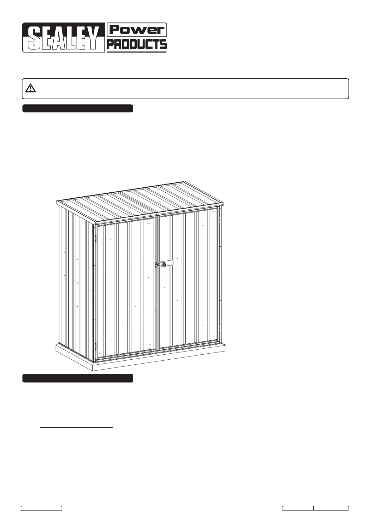
INSTRUCTIONS FOR: GALVANIZED STEEL
SHED 1.5 x 0.8 x1.5m (DOUBLE DOOR)
MODEL No: GSS150815
Thank you for purchasing a Sealey product. Manufactured to a high standard this product will, if used according to these instructions
and properly maintained, give you years of trouble free performance.
IMPORTANT: PLEASE READ THESE INSTRUCTIONS CAREFULLY. NOTE THE SAFE OPERATIONAL REQUIREMENTS, WARNINGS AND CAUTIONS.
USE THE PRODUCT CORRECTLY AND WITH CARE FOR THE PURPOSE FOR WHICH IT IS INTENDED. FAILURE TO DO SO MAY CAUSE DAMAGE
AND/OR PERSONAL INJURY AND WILL INVALIDATE THE WARRANTY. PLEASE KEEP INSTRUCTIONS SAFE FOR FUTURE USE.
© Jack Sealey Limited Original Language Version
WARNING! Ensure Health & Safety, local authority, and general workshop practice regulations are adhered to
when building this shed.
Keep the work area clean, uncluttered and ensure there is adequate lighting.
Keep children and unauthorised persons away from the working area.
DO NOT use the shed for any purpose other than that for which it is designed.
Use appropriate safety clothing including eye protection.
Note! The assembly of this product will require assistance.
1. SAFETY INSTRUCTIONS
2. INTRODUCTION
Before commencing the assembly, we recommend that you read the instructions thoroughly. Your new shed
comes with all the holes pre drilled to make for fast easy assembly. We recommend that you assemble the
shed using a trestle table or sawhorses and planks. This will ensure that you are working off the ground and
make it easier for you. Assembly is a two person job and should not be attempted in windy conditions.
Sequence of operations.
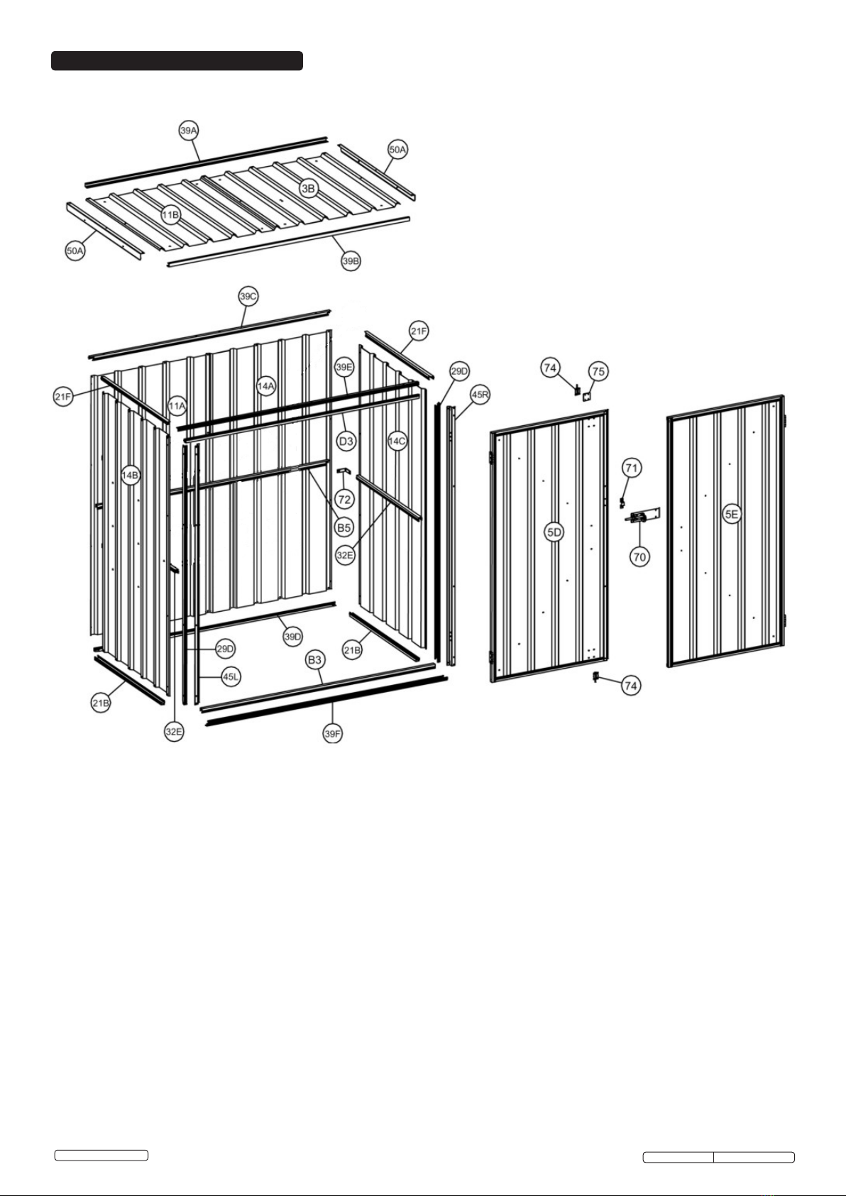
2.1 Check all parts against the component list.
2.2 Assemble the rear wall panels.
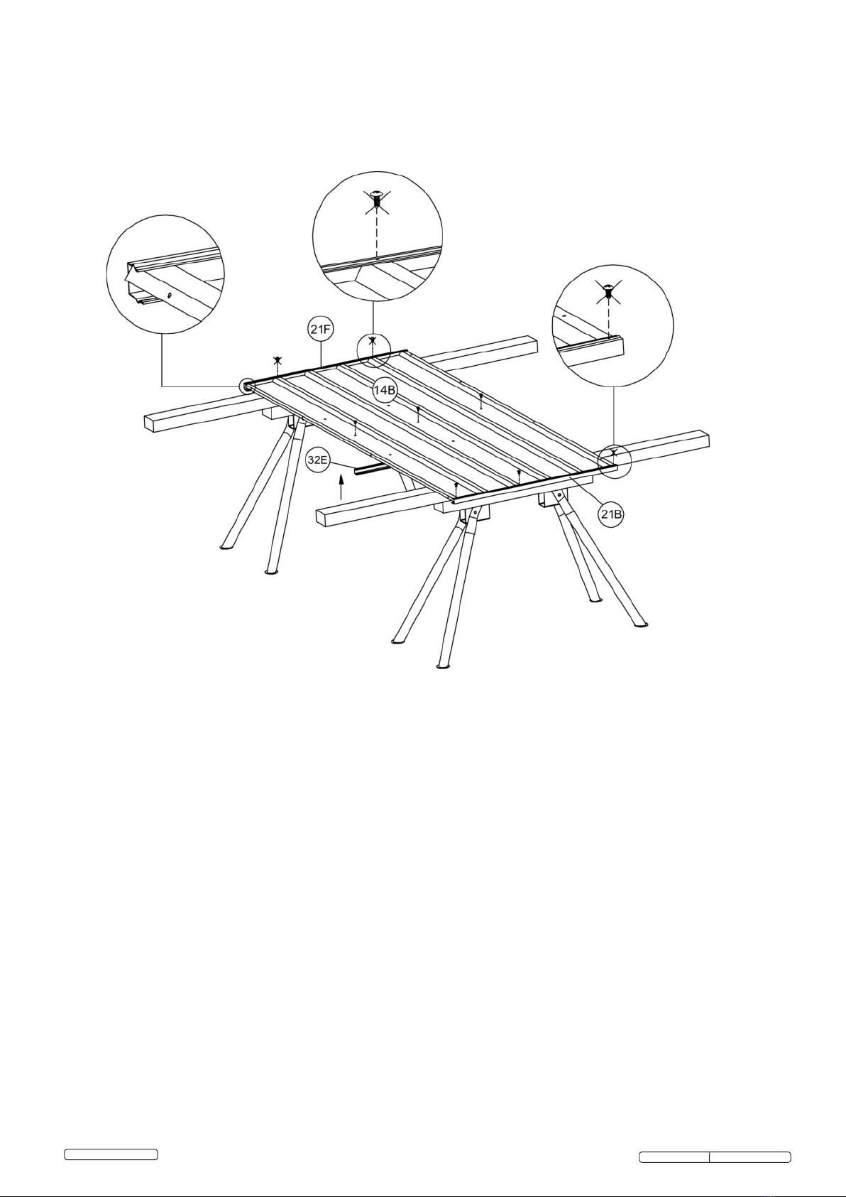
2.3 Assemble the side wall panels.
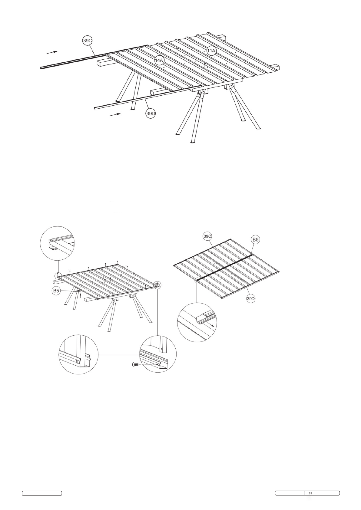
2.4 Assemble the roof panels.
2.5 Assemble the front wall panels.
2.6 Assemble door.
2.7 Fit the panels together.
2.8 Prepareandttoplinthslab.
GSS150815 Issue: 1 - 24/08/12

3. CONCRETE PLINTH SLAB
4. TOOLS REQUIRED
Concrete Slab: It is recommended that your new shed is secured to a concrete slab as shown below.
Please ensure that your site is level. It is recommended that your slab is 100mm thick, you use a plastic
membrane and a suitable reinforcing mesh. We recommend that you make your slab 100mm bigger than the
base dimensions of your shed. This will allow for a 50mm edge around your shed. We recommend that you
slope the 50mm edges downward by 10mm so that rain water will drain away from your shed.
5. CONTENTS
Check contents: Lay out all components with the part numbers facing upwards and check off against the parts
lists on the next four pages. In the unlikely event of a missing component please contact you local Sealey dealer.
GSS150815 Issue: 1 - 24/08/12
© Jack Sealey Limited Original Language Version

GSS150815 Issue: 1 - 24/08/12
© Jack Sealey Limited Original Language Version
sheet 1500 x 770
sheet 1500 x 735
sheet 1500 x 770
sheet 1500 x 770
sheet 855 x 770
sheet 855 x 735
sheet 1445 x 710
sheet 1445 x 710

GSS150815 Issue: 1 - 24/08/12
© Jack Sealey Limited Original Language Version

GSS150815 Issue: 1 - 24/08/12
© Jack Sealey Limited Original Language Version
Ø4 x 10mm Rivet Ø3 x 10mm Rivet
Pad Shoot bolt
Part No (74)
Keeper Part No (71)
Pad Shoot bolt plate
Part No (75)
60mm Barrel shoot bolt
Part No (70)
Mid height wall bracket
Part No (72)
Base bracket

GSS150815 Issue: 1 - 24/08/12
5.1 Please note some component descriptions may differ in manual text to listings, always use pictures from
listingstodoublecheckcomponentidentity.ieM8xingsmaybesuppliedinlieuof5/16”.
© Jack Sealey Limited Original Language Version

6. PARTS DIAGRAM
GSS150815 Issue: 1 - 24/08/12
© Jack Sealey Limited Original Language Version

7. ASSEMBLY
GSS150815 Issue: 1 - 24/08/12
7.1 ASSEMBLE THE REAR WALL PANELS
7.1.1 Youwillnditeasiertoassembletheshedusingtrestles,withtimberstuddingofequalorgreaterpanel
length. Trestles are available separately from your Sealey Dealer. Attach the studding to trestles with
equaloverhangusingnyloncabletiesorsimilar“safe”method.
7.1.2 Place panel 14A and 11A on your work table and join them together with the 10mm long self tapping screws.
See the pre-punched holes and diagram below.
7.1.3Fittopandbottomchannels39Cand39Dtopanelsbyrstlyslidingandnallytappingintoplaceasindicated
byarrowsinthediagramsNotethatthesmallerangeonthechannelsshouldalwaysbeadjacenttotheout
side face of the panel; this prevents rainwater entering the compartment of the shed. The outside face is the
top face in the diagram below.
© Jack Sealey Limited Original Language Version

7.1.5 Fit item B5 the mid height wall channel to the panel and position it by the pre-punched holes and 10mm
longselftappingscrews.Notethischannelisttedwiththeatfaceuppermost,ie.nearestthe“top”,when
the shed is assembled.
7.1.6 With10mmlongselftappingscrewsxitems39Cand39Dtotopandbottomedges.
GSS150815 Issue: 1 - 24/08/12
7.1.4 An alternative method is to slide channels 39C and 39D as indicated by arrows in diagram above.
© Jack Sealey Limited Original Language Version

7.2.1 Place panel 14B on your work table.
7.2.2 Fittopandbottomchannels21Band21Ftopanelbyrstlyslidingandnallytappingintoplaceaspreviously
similarpanelbuild.Noteagainthatthesmallerangeonthechannelsshouldalwaysbeadjacenttothe
outside face of the panel. The outside face is the top face in the diagram.
7.2.3 Fit item 32E the mid height wall channel to the panel and position it by the pre-punched holes and 10mm
longselftappingscrews.Notethischannelisttedwiththeatfaceuppermost,ie.nearestthe“top”when
assembling the shed.
7.2.4 Withselftappingscrewsxitem21Btobottomedgeexceptinpositionmarkedwithasterisk*,anddo not
screwxitem21Ftotopedgeatthisstage.Seethosexingsmarkedwithasterisk*.
7.2 ASSEMBLE THE END WALL PANEL.
GSS150815 Issue: 1 - 24/08/12
Top Edge
© Jack Sealey Limited Original Language Version
*
*

GSS150815 Issue: 1 - 24/08/12
7.3 ASSEMBLE THE OPPOSITE END WALL PANEL
7.3.1 Place panel 14C on your work table.
7.3.2 Fittopandbottomchannels21Band21Ftopanelbyrstlyslidingandnallytappingintoplaceaspreviously
similarpanelbuild.Noteagainthatthesmallerangeonthechannelsshouldalwaysbeadjacenttotheout
side face of the panel. The outside face is the top face in the diagram.
7.3.3 Fit item 32E the mid height wall channel to the panel and position it by the pre-punched holes and 10mm
longselftappingscrews.Notethischannelisttedwiththeatfaceuppermost,ie.nearestthe“top”when
assembling the shed.
7.3.4 Withselftappingscrewsxitem21Btobottomedge,butdonotscrewxitem21Ftotopedgeatthisstage.
Seethosexingsmarkedwithasterisk*.
**
TOP
EDGE
© Jack Sealey Limited Original Language Version
Top Edge
*
*

7.4.1 Place both panels item 3B and 11B on your work table and join them together with the 10mm long self tapping
screws. See the pre-punched holes.
7.4 ASSEMBLE THE ROOF PANEL
GSS150815 Issue: 1 - 24/08/12
7.4.2 Fittopandbottomchannelsitem39Aand39Btopanelsbyrstlyslidingandnallytappingintoplaceas
previouslyexplainedin7.1.3.Notethatthesmallerangeonthechannelsshouldalwaysbeadjacenttothe
outside face of the panel. The outside face is the top face in both diagrams.
© Jack Sealey Limited Original Language Version

7.4.3 Fititem50A(angles)toeachedge,refertodiagramaboveforangeorientation.Fixwith10mmlongself
tapping screws.
GSS150815 Issue: 1 - 24/08/12
50A
© Jack Sealey Limited Original Language Version

7.5 FIT THE SUB ASSEMBLED REAR AND END PANELS TOGETHER.
7.5.1 Attach the end wall 14B to the rear wall 11A & 14A, then the opposite end wall 14C. Fix all walls with the
10mm long self tapping screws.
GSS150815 Issue: 1 - 24/08/12
14C
14B
14A
11A
© Jack Sealey Limited Original Language Version

7.6 INSTALL THE DOOR FRAME
7.6.1 Install the front frame items 39E and 39F as per following diagrams. The door mullion sections items 45L
and45Rarexedwith16mmlongselftappingscrews.Donotxselftappingscrewsmarked*inenlarged
balloonedviewsuntilafterthedoorjambitemD3hasbeentted.See7.6.2.
7.6.2 SlideD3thedoorjambintothetopchannelandxwith10mmlongselftappingscrews.
*
GSS150815 Issue: 1 - 24/08/12
*
© Jack Sealey Limited Original Language Version

7.6.3 Fitthecornerstiffenerbracketsitem72,xwith10mmlongselftappingscrews.
GSS150815 Issue: 1 - 24/08/12
© Jack Sealey Limited Original Language Version

GSS150815 Issue: 1 - 24/08/12
7.7 SUB ASSEMBLE THE DOORS.
7.7.1 Sandwichthestiffenerplateitem75betweenshootboltitem74anddooritem5Dand“pop”rivetallthree
items together. This arrangement is at the top and bottom of the door item 5D.
© Jack Sealey Limited
Original Language Version

7.8 INSTALL THE DOOR.
7.8.1 Fit the pre assembled door item 5C to the rear panel via the hinges. Fix hinges into pre-punched holes with
4mm diameter rivets. Check action of door before crimping rivets.
7.8.2 Fittheshootboltitem70andtheboltkeeperitem71andxwith10mmlongselftappingscrewsor4mm
diameterrivets.(ttingmethodAorB)
GSS150815 Issue: 1 - 24/08/12
© Jack Sealey Limited Original Language Version

GSS150815 Issue: 1 - 24/08/12
7.9 INSTALL THE ROOF
7.9.1 Selftappingscrewxthepre-assembledroofpanelfrom7.4;comprisingitems39A,39Band50A.
7.9.2 With the shed located centrally about the plinth slab, position the 6 anchor steel angles (base brackets), M8
machinescrewxtointernalcompartment.Thiswillrequire“spotting”anddrilling8mmdiameterholes
through to shed panels. Spot through holes to plinth slab, remove anchor angles (base brackets) and
masonrydrillslabforanchorbolts.AnchorboltsandM8machinescrewsaresupplied,see“FITTINGSPACK”.
7.9.3Insertanchorbolts,re-tsteelangles(basebrackets)andanchorshedtoplinthslab.
© Jack Sealey Limited Original Language Version

NOTE: It is our policy to continually improve products and as such we reserve the right to alter data, specifications and component parts without prior notice.
IMPORTANT: No liability is accepted for incorrect use of this product.
WARRANTY: Guarantee is 12 months from purchase date, proof of which will be required for any claim.
INFORMATION: For a copy of our latest catalogue and promotions call us on 01284 757525 and leave your full name and address, including postcode.
01284 757500
01284 703534
sales@sealey.co.uk
Sole UK Distributor, Sealey Group,
Kempson Way, Suffolk Business Park,
Bury St. Edmunds, Suffolk,
IP32 7AR
www.sealey.co.uk
Web
email
7.10 SHED USER SAFETY.
7.10.1 Fit safety covers L to 32E and R to 32E opposite side and any projecting screws to be made safe with self
tapper covers.
GSS150815 Issue: 1 - 24/08/12
72
© Jack Sealey Limited Original Language Version
See 7.6.3
Other manuals for GSS150815
1
Table of contents
Other Sealey Outdoor Furnishing manuals
Popular Outdoor Furnishing manuals by other brands

Hanover
Hanover CORT5PCSASH quick start guide

Forever Redwood
Forever Redwood NOAH'S ARC HAMMOCKS Assembly instructions

CASARIA
CASARIA Murcia 109023 manual

Safavieh Outdoor
Safavieh Outdoor Anaheim PAT6718 manual

Glendale
Glendale GL0020 Assembly instructions

Mimosa
Mimosa CORAL BAY LOUVRE PANEL GAZEBO Assembly instructions