Table of Contents
CORRESPONDENCE....................................................................................................................................... 2
SealMaster® LIMITED WARRANTY............................................................................................................... 3
SAFETY PRECAUTIONS AND CAUTIONS ....................................................................................................... 4
PRECAUTIONS ........................................................................................................................................... 4
CAUTIONS ................................................................................................................................................. 4
OPERATING INSTRUCTIONS ......................................................................................................................... 5
STARTUP –HYDRAULIC AGITATION............................................................................................................. 5
1-BEFORE STARTING THE ENGINE............................................................................................................. 5
STARTUP - COMPRESSOR............................................................................................................................. 6
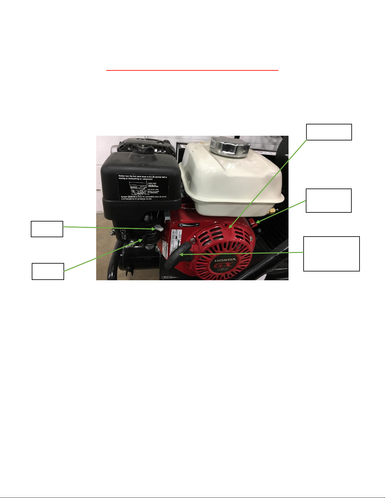
1-BEFORE STARTING THE ENGINE............................................................................................................. 6
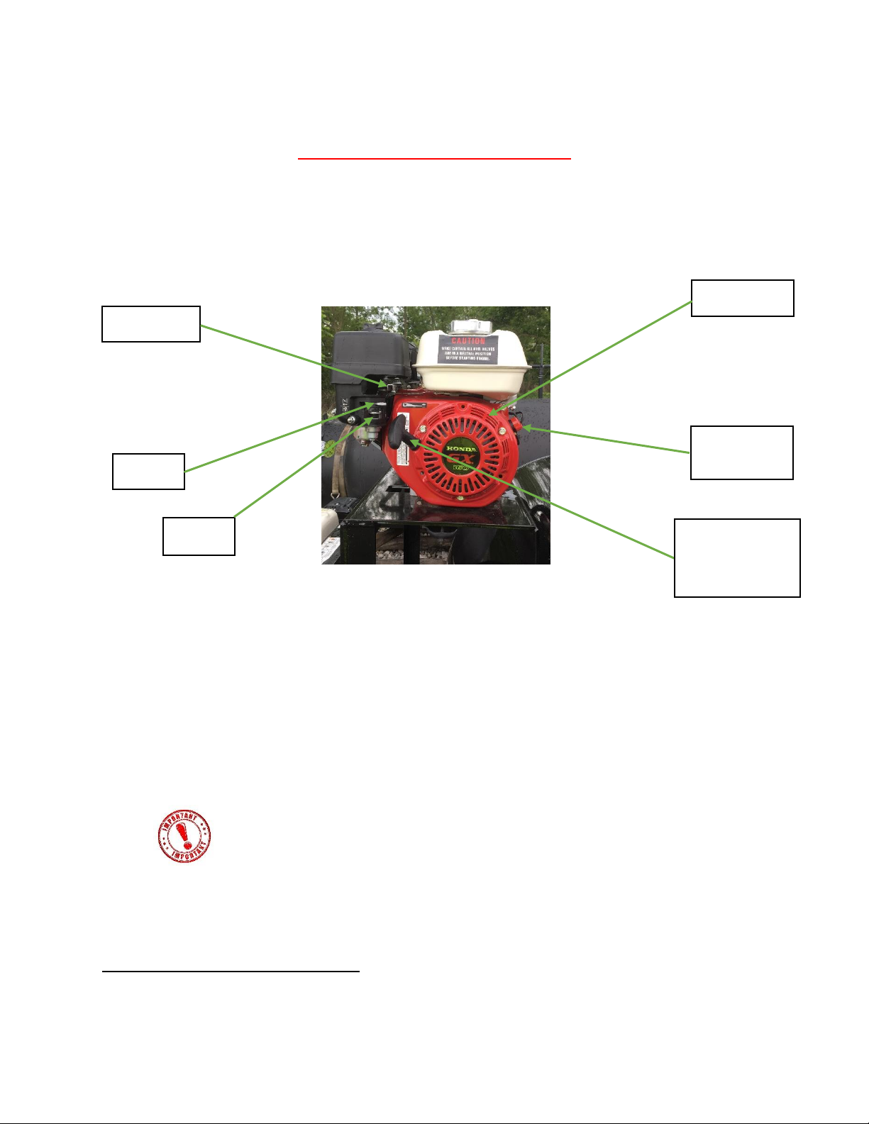
2-STARTING THE ENGINE .......................................................................................................................... 7
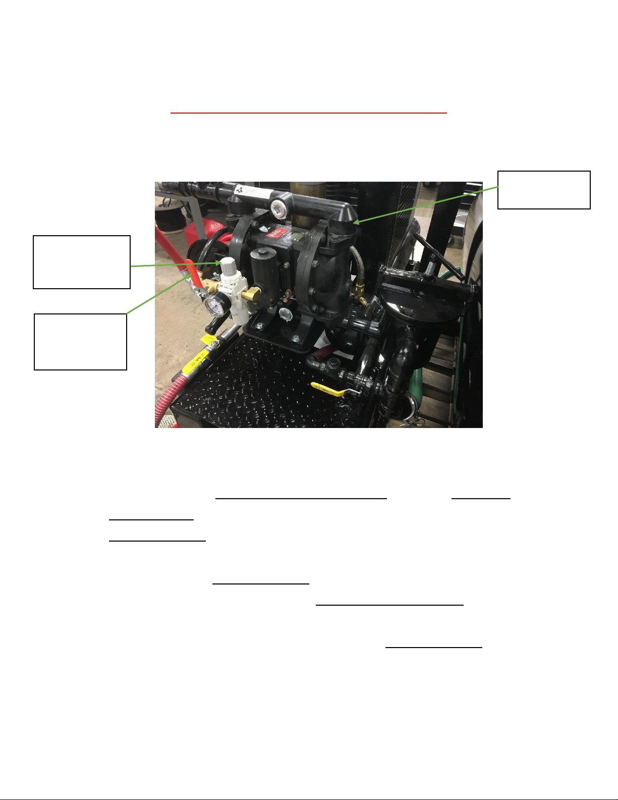
3-START TO PUMP MATERIAL................................................................................................................... 9
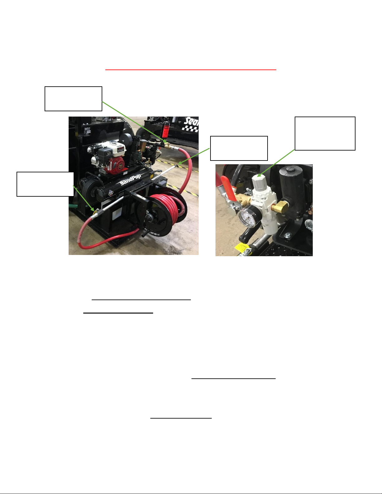
4-START THE SPRAY WAND..................................................................................................................... 10
5-WATER FLUSH...................................................................................................................................... 12
MAINTENANCE SCHEDULE .........................................................................................................................13
MAINTENANCE SCHEDULE...................................................................................................................... 13
TROUBLE SHOOTING GUIDE ...................................................................................................................15
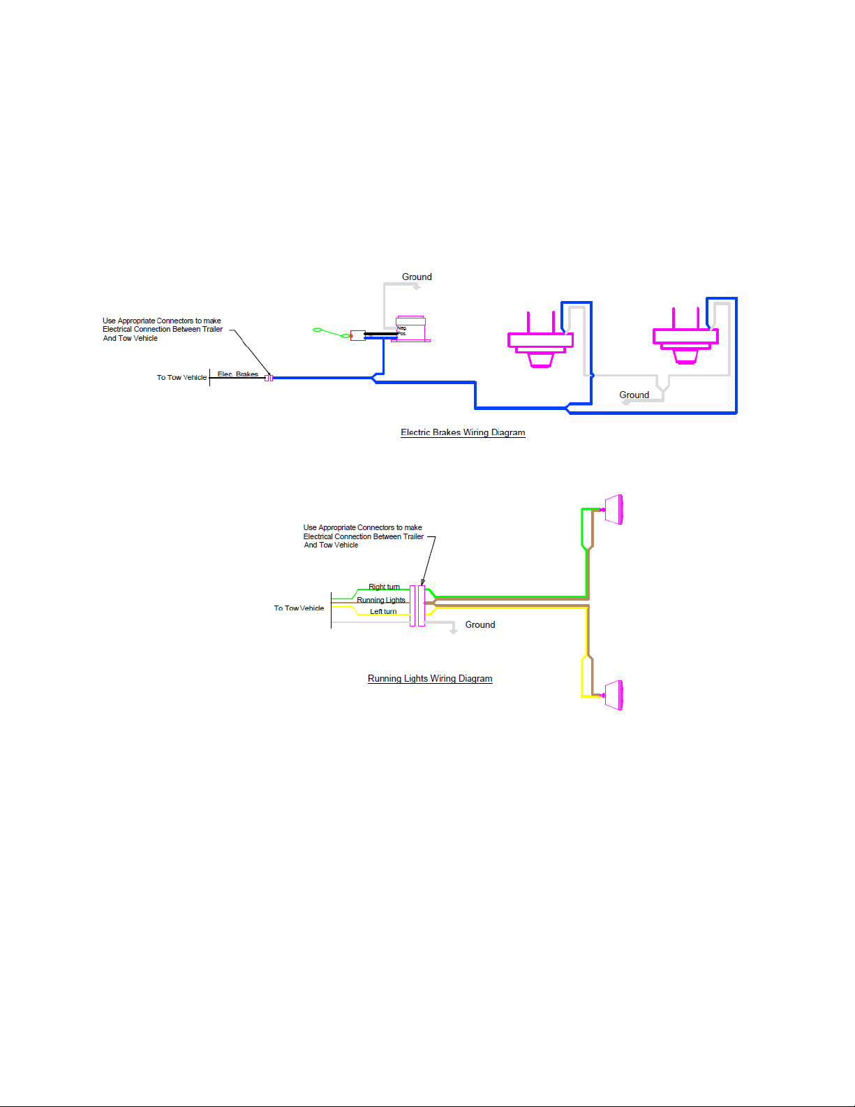
WIRING DIAGRAMS....................................................................................................................................17
ELECTRIC BRAKES AND RUNNING LIGHTS............................................................................................... 17
TANK CAPACITY CHART..............................................................................................................................18
MATERIAL DEPTH AND GALLON VOLUME.............................................................................................. 18
MACHINE PICTURES AND PARTS LIST........................................................................................................19
PARTS LIST PICTURE-1............................................................................................................................. 20
PARTS LIST PICTURE-2............................................................................................................................. 21
PARTS LIST PICTURE-3............................................................................................................................. 22
PARTS LIST PICTURE-4............................................................................................................................. 24
PARTS LIST PICTURE-5............................................................................................................................. 25
PARTS LIST PICTURE-6............................................................................................................................. 26
PARTS LIST FOR ARO 1” PUMP................................................................................................................27