SealMaster 300 User manual


S:\Engineering\13-Operator Manuals\Current\HEATED_ASPHALT_DIST_V2.8_NOV_2023.docx
HEATED ASPHALT DISTRIBUTOR
Owner’s Manual
Version 2.8
Issue Date: November 2023
Effective Date: January 2018
Version
Date
Changes
Approval
1.0
Original Issue
2.0
4/19
New Format and Updates
DS
2.1
6/19
Updated Wiring Diagrams
EK
2.2
10/20
Item 49 was P601A014
JG
2.3
10/21
Item 47 was P474A029
JG
2.4
1/22
Winterize Sheet Added
JG
2.5
4/22
Added Paint Page
JG
2.6
5/22
Breakaway Kit Change
JG
2.7
7/23
Item P932A001 Removed
JG
2.8
11/23
Picture / List Sequence
JG

Table of Contents
CORRESPONDENCE................................................................................................................ 3
SealMaster® LIMITED WARRANTY ......................................................................................... 4
SAFETY PRECAUTIONS AND CAUTIONS.................................................................................. 5
PRECAUTIONS......................................................................................................................... 5
CAUTIONS............................................................................................................................... 5
FIRST AID ................................................................................................................................ 6
STARTING THE ENGINE ........................................................................................................... 7
OPERATING INSTRUCTIONS ................................................................................................... 8
HEATING THE MATERIAL......................................................................................................... 8
PUMPING MATERIAL .............................................................................................................. 9
SPRAY BAR.............................................................................................................................. 9
DIESEL FLUSH........................................................................................................................ 10
MAINTENANCE TIPS.............................................................................................................. 10
PARTS LIST PICTURE –1 ........................................................................................................ 11
PARTS LIST PICTURE –2 ........................................................................................................ 12
PARTS LIST PICTURE –3 ........................................................................................................ 14
PARTS LIST PICTURE –4 ........................................................................................................ 16
PARTS LIST PICTURE –5 ........................................................................................................ 18
CHECKLIST............................................................................................................................. 19
BEFORE STARTING THE ENGINE............................................................................................ 19
STARTING THE ENGINE ......................................................................................................... 20
OPERATING INSTRUCTIONS WITH HYDRAULIC DRIVE .......................................................... 21
HEATING THE MATERIAL....................................................................................................... 21
PUMPING MATERIAL ............................................................................................................ 22
SPRAY BAR............................................................................................................................ 22
DIESEL FLUSH........................................................................................................................ 23
MAINTENANCE TIPS.............................................................................................................. 23

2
PARTS LIST PICTURE –6 ........................................................................................................ 24
PARTS LIST PICTURE –7 ........................................................................................................ 25
PARTS LIST PICTURE –8 ........................................................................................................ 27
PARTS LIST PICTURE –9 ........................................................................................................ 29
PARTS LIST PICTURE –10 ...................................................................................................... 31
PARTS LIST PICTURE –11 ...................................................................................................... 31
HEATED TACK TANK MACHINE MAINTENANCE.................................................................... 32
MAINTENANCE SCHEDULE.................................................................................................... 32
TROUBLESHOOTING GUIDE .................................................................................................. 33
HOW TO WINTERIZE YOUR EQUIPMENT............................................................................... 34
WIRING DIAGRAMS............................................................................................................. 35
ELECTRIC BRAKES AND RUNNING LIGHTS ............................................................................. 35
TANK CAPACITY CHART ....................................................................................................... 36
MATERIAL DEPTH AND GALLON VOLUME............................................................................. 36
ROPER 1-1/4” PUMP............................................................................................................ 37
PARTS LIST ............................................................................................................................ 37
PUMP DIAGRAM................................................................................................................... 38
ROPER 2” PUMP 3611 HZRV ................................................................................................ 39
PARTS LIST ............................................................................................................................ 39
PUMP DIAGRAM................................................................................................................... 40
MAINTENANCE AND STORAGE ............................................................................................ 41
MAINTENANCE ..................................................................................................................... 41
STORAGE .............................................................................................................................. 41

3
`ThorWorks Industries, Inc.
Purchased by __________________________ Model NO. _______________________
Company Name _______________________ Serial NO. _______________________
Address ________________________________ Acceptance Date ________________
City _____________ State______ Zip _______
CORRESPONDENCE
All Correspondence regarding this equipment, as well as general correspondence should be addressed to:
ThorWorks Industries, Inc.
PO Box 2277
Sandusky, OH 44870
In referring to the equipment, kindly state the Model Number, Serial Number and any part number involved
`

4
SealMaster® LIMITED WARRANTY
SealMaster warrants that its products are of quality material and workmanship. SealMaster agrees to replace,
within a period of one (1) year from date of delivery, or at its option, repair, without charge, any part of their
manufacture which proved defective. The repair or replacement will be free of charge F.O.B. Sandusky, Ohio,
providing the damaged part or parts are returned, freight prepaid, to SealMaster and investigation shows such
repair or replacement is made necessary by an inherent defect of material or workmanship.
It is hereby understood that engines, motors, pumps, or other components purchased by SealMaster for use
on its equipment are not warranted by SealMaster and are sold only with the standard warranty of the
manufacturer of that component.
SealMaster will make no allowances for repairs or alterations completed by outside sources unless
authorization is in writing and approved by an authorized SealMaster representative.
Any claims for defective material or workmanship must be made prior to the expiration of thirty (30) days
from the date failure occurs, and in all cases prior to the expiration of the warranty period of one (1) year. It is
the intent of this paragraph to limit SealMaster’s liability solely to the cost of replacement parts, F.O.B.
factory, or at the option of SealMaster to repair of the defective part or parts. No allowances for damages, lost
time, or any other claim will be recognized.
This warranty is null and void if other than genuine SealMaster parts are used.
SealMaster is constantly striving to improve their products. Changes in design and improvement will be made
whenever the manufacturer believes the efficiency of the product will be improved, without incurring any
obligation to incorporate such improvements in any machines which have been shipped or are in service.
In an effort to continue to improve product quality, SealMaster reserves the right to change specifications
without notice.
Any modification or alteration of this machine without prior approval of the manufacturer may void this
warranty.

5
SAFETY PRECAUTIONS AND CAUTIONS
PRECAUTIONS
•The operator must be aware that he is working with a mechanical device that
contains HOT materials, and must exercise caution at all times.
•Always wear eye and ear protection, long sleeve shirt, and gloves.
•Be aware of all CAUTION, WARNING, and DANGER signs on the machine.
•All employees should be trained in Emergency Burn First Aid.
•Read all Owners Manuals that come with this Machine.
•Make sure the operator is familiar with machine operation.
•Know the procedures for safe operation of propane-fired devices.
•Read and understand the MSDS Sheets for the material you are applying.
•Replace any hoses that show signs of wear, fraying or splitting.
•Be sure all fittings and joints are tight and leak proof.
•Do not operate the machine in the rain or closed building or confined area.
•Do not do maintenance work on the machine while in operation.
•The machine should not be left unattended when running.
CAUTIONS
•Never refuel engine while the burner is lit.
•Never expose the material to an open flame.
•Keep hands, feet, and clothing away from moving parts.
•Do not operate the machine without all guards in place.
•Do not point the spray nozzle at another person.
•Wear eye protection when operating the spray wand or spray bar.

6
SAFETY PRECAUTIONS AND CAUTIONS
FIRST AID

7
HEATED ASPHALT DISTRIBUTOR
APPLIES TO ALL TRAILER AND SKID VERSIONS
OPERATING INSTRUCTIONS
STARTUP
STARTING THE ENGINE
NOTE: If equipped with optional hydraulic drive upgrade refer to pages 18-26
•Set the fuel shutoff and choke levers to the on position.
•Set the throttle lever at ½ open.
•Set the engine on/off switch to on position.
•Pull start the engine.
•It is important that when you are done running the engine that the
fuel shutoff lever is turned to the off position. This keeps gasoline from
mixing with oil as you are driving.
Refer to the engine manual.
ENGINE
PULL
HANDLE
CHOKE
FUEL
THROTTLE
ON/OFF
SWITCH

8
HEATED ASPHALT DISTRIBUTOR
APPLIES TO ALL TRAILER AND SKID VERSIONS
OPERATING INSTRUCTIONS
HEATING THE MATERIAL
1. Attach Nut & Nipple #1 to your LP Gas tank.
The burner uses vapor propane, NOT liquid.
2. Slowly open the valve on the LP Gas Tank. Opening too fast can cause a check valve to
slam closed, reducing the available flow of gas.
3. Regulator #3 is pre-set for 30 psi. Turn the knob counter-clockwise to lower the
pressure. The burner #11, is rated for maximum heat output at 30 psi. Open gas shut-off
valve #7 slightly, depress the red push on gas pilot valve #8. This allows gas to flow thru
the burner, at the same time use the striker flint #10 to produce a spark.
Strike repeatedly until the gas ignites.
If the gas does not light within 5 seconds, release the red push button
and wait 10 minutes before trying again.
Once you have ignition, you must continue to depress the red push button on gas pilot valve
#8 for at least 10 seconds. This allows the thermocouple #9 to heat up, allowing the gas valve
to continue the gas flow. If the flame stays on, then open gas shut-off valve #7 all the way to
get maximum heat from the burner.
If the flame goes out, you will need to start over with the lighting process.
Anytime you want to decrease the flame intensity, slightly close gas shut-off valve #7.
4. The thermocouple #9 also acts as a safety. Should the flame go out because of wind, the
thermocouple immediately starts to cool off and stops the signal to the gas valve, which
then stops the flow of gas. This may take up to 30 seconds.
WAIT 10 MINUTES BEFORE TRYING TO RE-LIGHT THE BURNER.
5. Monitor material temperature on thermometer #13. As the material reaches the
desired temperature you can slightly close gas shut-off valve #7 to decrease the flame,
or just shut off the valve completely.
NEVER DRIVE WITH THE BURNER LIT!!

9
HEATED ASPHALT DISTRIBUTOR
APPLIES TO ALL TRAILER AND SKID VERSIONS
OPERATING INSTRUCTIONS
PUMPING MATERIAL
6. Open main tank valve #16 and recirculation valve #24. Close all other valves.
7. Start engine #23 only after reading the engine manual, provided with your
machine. Engine speed will determine the gallons per minute pumped.
8. Start by recirculating material. The material pump #22 draws material from
the tank, thru the basket strainer #17, thru the recirculation valve #24 and
into the top of the tank.
9. Uncoil the spray hose from the side hangars on the tank. Open spray hose
feed valve #25 and spray wand valve #27. Slowly start to close recirculation
valve #24. This will send some product down the spray hose and out the
wand spray tip 80/20 #28. Partially closing this valve allows you to adjust the
desired spray pressure.
NEVER CLOSE RECIRCULATION VALVE #24 COMPLETELY
SPRAY BAR
10. When using the spray bar #31, spray hose feed valve #25 and spray wand
valve #27 remain closed. Once you have recirculated product, slowly close
recirculation valve #24. Open spray tip valves #32 on the spray bar #31.
Position the machine, motion for the driver to start forward at approx. 4mph,
open spray bar feed valve #38,and also the #55 spray bar lever, to start
spraying. This opens all of the spray tip valves #32 at the same time. Once
again, recirculation valve #24 determines spray pressure, adjust accordingly.
11. The throttle on the engine #23 needs to be set to 3/4 or full position to
ensure there is enough speed is available for the material pump #22.
12. Run the pump pressure and speed at the lowest acceptable application
pressure to help reduce overspray.
13. You can control pressure by using the recirculation valve #24.

10
14. Close spray bar feed valve #38 or the #55 spray bar lever when you reach the
end of your pass, leave all the pump controls set. The spray will continue
when you open the spray bar feed valve #38 or the #55 spray bar lever.
15. Position the tires right next to the previous pass, this will give you the proper
overlap.
16. When finished, turn off the engine and close all valves and follow flushing
instructions below.
DIESEL FLUSH
17. Close main tank valve #16 and recirculation valve #24. Start engine #23.
18. Open diesel flush valve #15 on the bottom of the diesel tank #12.
19. Open spray hose feed valve #25 and spray wand valve #27 to flush the spray
hose and wand. To flush the spray bar open spray bar feed valve #38 or the
#55 spray bar lever on the spray bar #31 to the open position. When done,
turn off the engine and close all open valves.
20. Use only diesel fuel for flushing purposes.
21. Remove the lid from the basket strainer #17 and clean the basket.
Anytime you notice the spray pressure is decreasing, the
basket strainer #17 probably needs to be cleaned. Make sure you close main
tank valve #16 before you remove the lid.
MAINTENANCE TIPS
22. Adjust the V-belt #20 tension, by going halfway between the center of the
two pulleys and moving the belt up and down. It should move about ½”.
23. The material pump #22 has a mechanical seal, some leakage is normal. When
the seal plate cannot be tightened any more, the seal must be replaced.
24. The orifice is inside burner #11, needs to be cleaned occasionally. Soot and
spider webs can cause blockage of the flow of gas.
25. Always leave the LP gas hose #6 connected to a tank. If left
disconnected, insects will make their nest inside of it and block the flow of
gas.

11
HEATED ASPHALT DISTRIBUTOR
APPLIES TO ALL TRAILER AND SKID VERSIONS
PARTS LIST
PICTURE –1
PARTS LIST PICTURE –1
ITEM #
PART#
QTY.
DESCRIPTION
1
P933A001
1
NUT AND NIPPLE
3
P735A015
1
REGULATOR
5
P935A001
2
COUPLER
6
P669A005
1
LP GAS HOSE –10 FT.
7
P397A011
1
GAS SHUT-OFF VALVE
8
P735A016
1
GAS PILOT VALVE
9
P679A003
1
THERMOCOUPLE 24”
10
SS107A1
1
STRIKER FLINT
11
P662A003
1
BURNER COMPLETE
8GAS PILOT
10 STRIKER FLINT
1NUT & NIPPLE
3REGULATOR
5COUPLER
7GAS SHUT-OFF
11 BURNER
9THERMOCOUPLE
6LP GAS HOSE

12
HEATED ASPHALT DISTRIBUTOR
APPLIES TO ALL TRAILER AND SKID VERSIONS
PARTS LIST
PICTURE - 2
PARTS LIST PICTURE –2
ITEM #
PART#
QTY.
DESCRIPTION
13
P659A002
1
THERMOMETER
17
P50147B007
1
BASKET STRAINER COMPLETE
P50147B010
1
BASKET STRAINER COMPLETE - OPTIONAL
22
P640A029
1
1-1/4" ROPER MATERIAL PUMP
P640A084
1
2" ROPER MATERIAL PUMP - OPTIONAL
23
P458A022
1
ENGINE –HONDA 5HP
P458A050
1
ENGINE –HONDA 8HP - OPTIONAL
38
P397A012
1
SPRAY BAR FEED VALVE-1-1/4" BALL
P397A002
1
SPRAY BAR FEED VALVE-2" BALL - OPTIONAL
23 ENGINE
17 BASKET STRAINER
ASSEMBLY
22 MATERIAL PUMP
38 SPRAY BAR FEED
13 THERMOMETER

13
HEATED ASPHALT DISTRIBUTOR
APPLIES TO ALL TRAILER AND SKID VERSIONS
PARTS LIST
PICTURE - 3
24 RECIRCULATION
25 SPRAY HOSE FEED
12 DIESEL TANK
38 SPRAY BAR FEED
17 BASKET STRAINER
ASSEMBLY
39 BASKET
13 THERMOMETER
16 MAIN TANK
15 DIESEL FLUSH
14 CAP

14
HEATED ASPHALT DISTRIBUTOR
APPLIES TO ALL TRAILER AND SKID VERSIONS
PARTS LIST
PARTS LIST PICTURE –3
ITEM #
PART#
QTY.
DESCRIPTION
12
P50400B003
1
DIESEL TANK
13
P659A002
1
THERMOMETER
14
P464A002
1
TWIST CAP
15
P397A001
1
DIESEL FLUSH VALVE-3/4“BALL
16
P397A012
1
MAIN TANK VALVE-1-1/4" BALL BRASS
P397A002
1
MAIN TANK VALVE- 2" BALL BRASS - OPTIONAL
P397A002
1
GRAVITY VALVE- 2" BALL BRASS - OPTIONAL
17
P50147B007
1
BASKET STRAINER COMPLETE
P50147B010
1
BASKET STRAINER COMPLETE - OPTIONAL
24
P397A012
1
RECIRCULATION VALVE-1-1/4" BALL
P397A002
RECIRCULATION VALVE-2" BALL –OPTIONAL
25
P397A001
1
SPRAY HOSE FEED VALVE-3/4“ BALL BRASS
38
P397A012
1
SPRAY BAR FEED VALVE-1-1/4" BALL
P397A002
1
SPRAY BAR FEED VALVE-2" BALL - OPTIONAL
39
P50313B
1
STRAINER BASKET
P50313A
1
STRAINER BASKET - OPTIONAL

15
HEATED ASPHALT DISTRIBUTOR
APPLIES TO ALL TRAILER AND SKID VERSIONS
OPERATING INSTRUCTIONS
PICTURE - 4
19 SHEAVE
21 SHEAVE
40 BUSHING
18 BUSHING
20 V-BELT
32 SPRAY TIP VALVE
29 SEAT
28 SPRAY TIP 80/20
31 SPRAY BAR ASSEMBLY

16
HEATED ASPHALT DISTRIBUTOR
APPLIES TO ALL TRAILER AND SKID VERSIONS
PARTS LIST
PARTS LIST PICTURE –4
ITEM #
PART#
QTY.
DESCRIPTION
18
P740A006
1
BUSHING 1” BORE
19
P661A033
1
SHEAVE 14-3/4” O.D.
20
P660A030
1
V-BELT B70
21
P661A034
1
SHEAVE 4-3/4” O.D.
28
P449A011
6
SPRAY TIP 80/20 1/4" NPT STEEL
29
P602A003
1
SEAT - OPTIONAL
31
P50246TAW
1
SPRAY BAR ASSEMBLY - OPTIONAL
32
P397A009
5
SPRAY TIP VALVE-1/2” BALL BRASS
40
P740A043
1
BUSHING 3/4” BORE
17
HEATED ASPHALT DISTRIBUTOR
APPLIES TO ALL TRAILER AND SKID VERSIONS
PARTS LIST
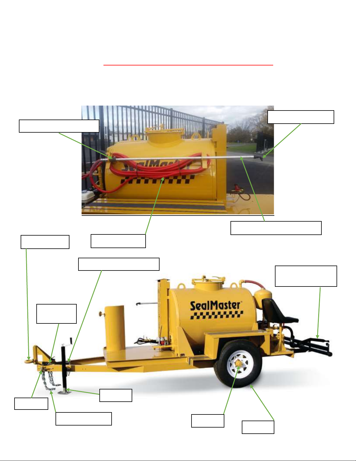
PICTURE - 5
26 SPRAY HOSE
27 SPRAY WAND VALVE
28 SPRAY TIP 80/20
41 SPRAY WAND ASSEMBLY
34 TIRE
37 COUPLERS
33 AXLE
35 SAFETY BREAK-AWAY
36 JACK
55 SPRAY BAR
LEVER-KIT
43 SAFETY CHAIN
45 TRAILER
PLUG
44 HOOK

18
HEATED ASPHALT DISTRIBUTOR
APPLIES TO ALL TRAILER AND SKID VERSIONS
PARTS LIST
PARTS LIST PICTURE –5
ITEM #
PART#
QTY.
DESCRIPTION
26
P754B025
1
SPRAY HOSE –50 FT.
27
P397A010
1
SPRAY WAND VALVE-3/4” BALL CARBON STEEL
28
P449A011
6
SPRAY TIP 80/20 1/4" NPT STEEL
33
P511A013
1
TR 300 AXLE
33
P511A013
2
TR 575 AXLE
34
P514A017
2
TR 300 TIRE ASSEMBLY
34
P514A017
4
TR 575 TIRE ASSEMBLY
35
P518A008
1
BREAKAWAY KIT –4 BOLTS
P518A004
1
BREAKAWAY KIT BEFORE 10/2019
36
P551A008
1
JACK ASSEMBLY
37
P553A008
*
2-5/16” BALL COUPLER
37
P646A003
*
PINTLE EYE COUPLER
41
P50273E
1
SPRAY WAND ASSEMBLY
43
P531A004
2
SAFETY CHAIN
44
P517A002
2
HOOK (PART OF SAFETY CHAIN)
45
P51PA007
1
TRAILER PLUG
55
P50247LK
1
SPRAY BAR LEVER KIT
This manual suits for next models
4
Table of contents
Other SealMaster Construction Equipment manuals


Popular Construction Equipment manuals by other brands


Volvo
Volvo L150H manual

Schmalz
Schmalz SK-JU-110-2000-SRS63-3000-VSL-EX Operating and maintenance instructions

MULTIQUIP
MULTIQUIP MC12PH Operation and parts manual

Talet Equipment
Talet Equipment Mini Auger Bucket Parts and operation manual

Dynapac
Dynapac CA702 instruction manual

Rockler
Rockler 42826 manual


