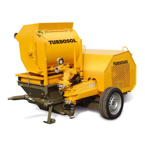
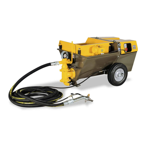
Turbosol POLI T Specification sheet

ITALIANO
ENGLISH
Serial number
CT. 200.401
PUMPING SYSTEMS FOR THE BUILDING INDUSTRY
INSTRUCTIONS FOR USE AND MAINTENANCE
COMPREHENSIVE CATALOGUE & SPARE PARTS

3
1. - General information 5
1.1 - Introduction
1.2 - General information
2. - Description of the machine 6
2.1 - Type of machine 6
Manufacturer’s rating plate
Position of the rating plate
Position of the machine serial number
2.2 - Description of the machine 7
2.3 - Machine size 8
2.4 - Technical data 8
3. - Machine transportation 9
3.1 - Transportation
4. - Using the machine 10
4.1 - Operating principle 10
4.2 - Pumpable materials 10
Applications 11
Choice of pump
Choice of spray gun
4.3 - Preliminary operations 12
Machine position
Electrical connection
Hoses 13
Hose anchorage
Couplings
Connections 14
4.4 - Starting 15
Preventive checks
Calibrating the pump 16
Starting 18
Preparing the batch 20
Conveying and spraying the mix
4.5 - Clean-up at end of work 22
4.6 - Replacing the pumping unit 24
5. - Machine maintenance 26
5.1 - Maintenance for which
the operator is responsible 26
Daily operations
5.2 - Maintenance to be carried out
by qualied personnel 27
6. - Troubleshooting 28
6.1 - No material comes out the spray gun 28
6.2 - Other problems 29
6.3 - Work by the operator 30
6.4 - Work by qualied personnel 30
7. - Responsibility of the operator 32
Table 1 - Machine casing 34
Table 2 - Motor – Drive unit 36
Table 3 - Pump 2L6 38
Table 4 - Pump T25 40
Table 5 - Pump 60.12 42
Table 6 - Oversize pan mixer 44
Table 7 - Switchboard 46
Table 8 - Remote control 48
Table 9 - Vibrating sieve 50
Table 10 - Complete compressor code 216.415 52
Table 10 A -Compressor 54
Table 11 - Accessory box code 201.112
for traditional mortars 56
Table 11 A - Accessory box code 201.112
Gun and hoses 58
Table 12 - Accessory box code 201.067
for ready-mix materials 60
Table 12 A - Accessory box code 201.067
Spray gun 62
Table 12 B - Accessory box code 201.067
Hoses 64
Table 13 - Accessory box code 201.071
for skim coats 66
Table 13 A - Accessory box code 201.071
Gun and hoses 68
Table 14 - Accessory box code 201.089
for self-levelling screeds 70
ACCESSORIES
Table 15 - Extensions 74
Table 16 - Guns 76
Table 17 - Nozzles 78
Table 18 - Injection device 80
Table 18 A - Pressure limiting device unit 82
Table 18 B - Gun - Hoses 84
Table 19 - Litre-counter 86
WIRING DIAGRAMS
Table 20 - Wiring diagram 90
CONTENTS
USE AND MAINTENANCE SPARE PARTS
3
USER GUIDE
IMPORTANT
Read and carefully follow the instructions contained in this
booklet. By doing so, you will thus help prevent accidents,
be fully covered by the manufacturer’s warranty, and have
always available an equipment that is perfectly efficient
and ready to use.
Operation and maintenance of this equipment must be
performed only by skilled personnel who are well aware of
the dangers inherent to the machinery itself.
All standards aimed at the prevention of work accidents
must be rigorously observed, as must all regulations
covering safety on the jobsite.
The manufacturer shall not be liable in any manner
whatsoever for injury or damage to persons or things
resulting from unauthorized changes in or modification of
this equipment.
MIXING, CONVEYING AND SPRAYING MACHINE
FOR READY-MIX MORTARS, TRADITIONAL
MORTARS AND FINISHING COATS
POLI T
Machine serial number:
You are strongly advised to enter your machine’s serial
number in the space above which must always be referred
in order to facilitate the work of the personnel in charge,
and it must likewise be mentioned when requesting service
assistance or spare parts.
We reserve the right to make any technical modification
whatsoever in the interests of improving this machinery,
even if such eventual modifications are not referred to in
this booklet.
Written authorization from Turbosol Produzione SpA must
be obtained for any and all reprinting or reproduction, even
in part, of the information contained in this booklet.

45
C - Ensure that no person is near the air outlets.
D - Never point the spray gun at persons.
E - Electrical components are present that may be live.
A - The hopper is fitted with a safety device.
Opening the safety grid stops the agitator.
B - The mixer is fitted with a safety device.
Opening the safety grid stops the mixer.
This user guide must
be read prior to
operating the machine
DESCRIPTION
This user guide must
be read with regard to
routine and extraordinary
maintenance
Warning:
Risk of electrical shock
LABELS
CAUTION!
A
E
D
B
C

45
The POLI T mixing, conveying and spraying machine
for ready-mix mortars, traditional mortars and structural
mortars may be provided with various accessories and
consequently not all the components described in this
guide are necessarily mounted on your machine.
We have done our best to illustrate the different versions
clearly so that you can easily identify the servicing and
maintenance instructions applicable to your machine.
Please read the following instructions carefully before
starting your machine and scrupulously comply with them
thereafter.
Do not hesitate to contact the TURBOSOL PRODUZIONE
S.P.A. customer service department for any further
information.
TURBOSOL PRODUZIONE S.P.A.
Via Volta, 1
31030 Pero di Breda di Piave (TV) - ITALIA
Tel. 0039 - 0422 - 90.2.51
Fax 0039 - 0422 - 90.44.08
http://www.turbosol.com
e-mail: [email protected]
TURBOSOL machines
Years of experience and continuous development lie
behind these machines. Acquired know-how plus high
quality standards are essential for manufacturing a long-
lasting, extremely reliable machine with low operating
costs.
Precautions to be taken with the machine in
operation
Maintenance or repairs should only be carried out with the
machine at a standstill. Any protective or safety devices
that need to be removed in order to carry out work should
be remounted upon completion of the same.
Maintenance and care
Maintenance and care are of the utmost importance if
the machine is to live up to expectations. It is therefore
essential to comply with the recommended maintenance
intervals and to meticulously carry out the necessary
work.
Safety
This symbol is to be found in this guide beside every
reference to safety or correct use of the machine and
should be scrupulously observed.
Service personnel should also be informed of the safety
regulations. General regulations relating to safety and
accident prevention provided for under local laws should
likewise be observed.
Training
This symbol indicates that the operator should be
specifically trained in order to carry out the operation
correctly.
TURBOSOL SERVICE
For any trouble with the machine or for spare parts,
please contact the TURBOSOL dealer.
1.1 - INTRODUCTION
1 - GENERAL INFORMATION
1.2 - GENERAL INFORMATION

6
7
Position of the rating plate
The rating plate (1) is fixed onto the machine hopper.
Position of the machine serial number
The machine serial number (2) is punched onto the hopper
as well as on the rating plate.
2.1 - TYPE OF MACHINE
Manufacturer’s registration plate
The type of machine (A), its serial number (B), and data
on the machine’s operating power are printed on the
manufacturer’s registration plate.
The meaning of the various symbols used is as follows:
(A) = Type of machine: POLI T EV (/MP)
POLI T = Mixing, conveying and spraying machine
for ready-mix mortars, traditional mortars
and nishing coats
EV = Electrical version
with variable-speed drive
/MP = With pan mixer
(B) = Machine serial number: NNNNN/AA
NNNNN = Machine serial number.
/AA = The year of manufacture
2 - DESCRIPTION OF THE MACHINE
E-mail:[email protected] - http://www.turbosol.com/
AB
2
1

6
7
Optional:
Complete vibrating sieve.
Device for injection of cemeticious mixer or controlled
pressure.
Water gauge.
Mushroom dish for pan mixer with scraper.
Spray gun for thick layer ready-mix plasters.
Spray guns for injection of cementicious slurries, stuccoing
and pressure pointing with or without air inject.
Nozzle for pumping mortars.
Screw and stator pump type 60.12
Compressor 250 l/min –1.5 kW - 380 V (incorporable).
Compressor 590 l/min - 3 kW - 380 V for skim coats
(separate).
Main components:
The machine basically comprises:
a hopper (3) with agitator (4)
a gearmotor (5)
a switchboard (6)
a pumping unit (7)
a vibrating sieve (8) with vibrator (9), (for traditional plasters);
a pan mixer (/MP version) (10) (for traditional or ready-mix
plasters or structural mortars)
with mixer (11)
a compressor (optional) (12).
2.2 - DESCRIPTION OF THE MACHINE
8
5
7
6
10
4
12
9
Standard equipment:
• Unitized body with tyres
• 120-litre hopper with agitator.
• Variable output with mechanical variable-speed drive.
• Electric motor.
• Switchboard to CE standards with sockets and selectors
for connecting and using the machine.
• Socket for pan mixer (/MP).
• Remote electric control (with 33 metres of cable) or
pneumatic control to be selected from the switchboard.
• Vibrating sieve with Ø 8 mm mesh (for traditional
plasters).
• 120-litre pan mixer with 1.8 kW motor and reverse (/MP
version for traditional, ready-mix plasters and structural
mortars).
• Screw and stator pump in rubber type T25 (for traditional
plasters).
• Screw and stator pump in rubber type 2L6 (for ready-mix
plasters and structural mortars).
• Pump outlet with cam-lock coupling DN 50
• 30 metres (20 + 10) of Ø 35 mortar hose with cam-lock
couplings (for traditional plasters and structural mortars).
• 31 metres of Ø 13 air hose with quick couplings
(for traditional plasters and structural mortars).
• 35 metres (20 + 10 Ø 35 + 5 Ø 25) of mortar hose with
cam-lock couplings (for ready-mix plasters).
• 36 metres (20+16) of Ø 13 air hose with quick couplings
(for ready-mix plasters).
• Accessory box.
• Technical documentation.
11
3

89
Machine pressure switch setting minimum
maximum
2 bar
4 bar
Compressor pressure switch setting minimum
maximum
3 bar
5 bar
Compressor relief valve calibration 7 bar
Air supplied by built-in compressor at 2 bar 250 l/m’
Supply voltage 400 VAC ±10%
Supply frequency 50 Hz
Auxiliary circuit voltage 24 VAC
Short-circuit current maximum 6 KA
Number of starts per hour maximum 24
MACHINE
Machine electric motor power 5,5 kW
Motor rated current 12,2 A
BUILT-IN COMPRESSOR
Electric motor power 0,8 kW
Rated current 2,2 A
OVERSIZE MIXER
Electric motor power 1,85 kW
Rated current 4,36 A
Reducer gear oil change (SHELL OMALA 220 - 2,8 l) every 3.000 hours
Variable-speed drive oil change (SHELL A.T.F. DEXTRON III - 1,0 l) every 3.000 hours
Compressor oil change (TURBO DIESEL 15W40 - 0,6 l) every 3.000 hours
Oversize mixer reduction gear oil change (AGIP DELIUM VSF 320 - 0,7 l) every 3.000 hours
Hopper capacity 120 l
Mixer capacity 120 l
Working environment temperature from -5° to + 35° C
LwA guaranteed (90% condence level, directive 2000/14/CE),
tested by ISET, Notied Body No. 0865 77 dB(A)
Version POLI T EV
1.850 mm 710 mm 650 mm 205 kg
WEIGHT
The overall size and gross weight (ready to operate) of the machine are given below.
LENGTH WIDTH
2.4 - TECHNICAL DATA
HEGHT
Version POLI T EV/MP (pan mixer)
1.850 mm 710 mm 1.210 mm 295 kg
LENGTH HEGHT WEIGHTWIDTH
N.B.: # the operator must wear personal ear protection
which guarantees a sound reduction of at least 10 dB(A).
2.3 - MACHINE SIZE

89
Attach the ropes to the relative eyebolts located on the
sides of the machine.
Material theoretical output°
Maximum pump pressure
Maximum pumpable particle size
Delivery height (approx.)*
Delivery distance (approx.)*
Material delivery rubber hose **
0 ÷ 150 l/m’
20 bar
8 ÷ 10 mm
40 - 50 m
80 - 100
Ø 50 x 66 mm
0 ÷ 45 l/m’
25 bar
8 ÷ 10 mm
30 - 40 m
60 - 80 m
Ø 35 x 49 mm
0 ÷ 45 l/m’
45 bar
4 ÷ 6 mm
50 - 60 m
80 - 100 m
Ø 35 x 49 mm
Ø 25 x 37 mm
PUMPS 60.12
(optional)
T25
(optional)
2L6
(standard)
N.B.: ° The output may vary according to the viscosity, quality and composition of the mix, pump wear, mortar hose
diameter and length, pumping height.
* maximum distance and height not reachable at the same time.
These data are not absolute, but depend on the quality of the materials to be pumped, their consistency, pump
capacity and diameter of the used hoses.
** only use hoses made specically for this machine.
3.1 - TRANSPORTATION
3 - TRANSPORTATION
Do not lift the machine using a lift truck.
Use: one hook and two ropes that have been tested
and approved for lifting 500 kg.
Before lifting the machine, ensure that no person is
near it.

10
11
Several basic concepts are given below regarding the
preparation of traditional mixes that may be conveyed with
POLI T:
• the aggregates must be within the granulometry
curve:
for example, use aggregates that have
particle size: 1/3 between 0 and 1 mm inclusive
1/3 between 1 and 3 mm inclusive
1/3 between 3 and 5 mm inclusive.
• for a batch of 140 litres, 50 kg (one bag) of
cement or plasticized lime are normally used.
• the water/cement ratio should be approx. 0.6:
i.e. 25 - 35 litres of water for a batch of 140 litres,
depending on the quantity of cement and the
moisture content of the aggregates.
• when using ready-mix mortars (mortars with
controlled shrinkage, normal or light cement-
based ready mixes), the instructions provided
by the producer of the material must be carefully
followed, in particular with regard to the quantity
of water and the mixing time.
POLI T basically consists of a hopper with built-in agitator,
which receives the mixed material, and a screw pump for
pumping the material. It may be fitted with a pan mixer
(/MP version) for preparing the mix.
The mix is unloaded into the hopper then pumped by
the screw pump to the place of application; the material
is conveyed through a hose to the spray gun (which may
differ according to the types of materials used), where air
coming from the auxiliary compressor is introduced to
propel the mix.
Pump output may be adjusted by means of a regulating
handwheel (13).
The output should only be adjusted with the motor
running, otherwise the variable-speed drive could
be broken.
The nozzleman starts and stops
the machine by opening and closing
the air control valve (14)
located on the gun,
or through a remote control
via cable (15).
A water gauge may be installed for batching the water
and a vibrating sieve for sieving the material.
4.1 – OPERATING PRINCIPLE
4 - USING THE MACHINE
4.2 - PUMPABLE MATERIALS
13
14
15

10
11
Applications
POLI T mixes, pumps, sprays and injects various types of
materials such as:
• Traditional mortars and plasters.
• Ready-mix mortars and plasters.
• Thermal-acoustic insulating mortars and plasters.
• Mortars and plasters for finishing coats, smoothed or
rusticated decorative skim coats.
• Mortars and plasters for thin-layer coats.
• Plasters for filling and pressure pointing joints and gaps.
• Substrates for lightweight and self-levelling screeds.
• Masonry mortars and adhesive mortars for blocks and
plasterboard.
• Mortars and cementitious slurries for consolidation
grouting.
• Special fibre-reinforced cement mortars and slurries for
structural repair.
• Fire-retardant coatings.
• Cementitious grouts and slurries,
(it is advisable to use the mushroom dish for pan mixer
with scraper).
• Refractory and wearproof mortars.
• Heavy mortars for filling moulds, special containers and
ballast.
• Intumescent plasters.
Choice of pump
Three different types of pumps are available, each one
particularly indicated for a certain type of material:
STANDARD CONFIGURATION:
• Pump 2L6 (screw code 250.123, stator code 263.184)
for ready-mixed materials with particle size 4 ÷ 6 mm
(grit);
• Pump T25 (screw code 250.089, stator code 238.030)
for traditional mortars with particle size 8 ÷ 10 mm.
OPTIONAL:
• Pump 60.12 (screw code 250.136, stator code 263.366)
for self-levelling screeds.
Choice of spray gun
The specific gun is used according to the material:
• Gun (code 216.246) for traditional and controlled-
shrinkage mortars (accessory box code 201.112).
• Gun (code 216.252) for ready-mixed plasters and
structural mortars (accessory box code 201.067).
• Gun (code 216.266) for skim coats, plastics,
waterproofing (accessory box code 201.071).
• Nozzle Ø 50 (code 251.193) for self-levelling substrates
(accessory box code 201.089).
• Gun (code 216.251) for thick coat application ready-mix
plasters (optional).
• Gun (code 216.256) for filling gaps (optional).
• Gun (code 216.496) for joints (optional).
• Gun (code 216.299) for injections (optional – injection
device).
• Nozzle Ø 25 (code 216.255)
Ø 35 (code 216.216) for pumping mortars and
self-levelling screeds (optional).

12
13
Electrical connection
Connect the machine to the site switchboard using a
neoprene (wearproof rubber) cable marked H07 RN-F and
having a minimum section:
4 x 4 mm for distances up to 20 m
4 x 6 mm for distances up to 50 m
4 x 10 mm for distances up to 100 m.
Using an electric cable with an unsuitable section
jeopardises machine operation.
The site switchboard should have:
• a minimum power of 12 kVA
• adequate earthing
• 35 A fuses (type Am)
• high-sensitivity differentials (30 mA)
• and in any case be in compliance with current regulations
in the country where the machine is being used.
Connect the earth terminal of the machine to the site
switchboard earth stake by means of a cable having a
minimum section that is never less than 16 mm².
If the machine is powered through a generating set,
use a 30 kVA set.
4.3 - PRELIMINARY OPERATIONS
Machine position
Place the machine as level as possible: the maximum
allowed gradient is 5° both lengthwise and crosswise.
The machine should be positioned on site where the radius
of action of the hoses may be best exploited.
Wedge the wheels.
Prepare all the material for cleaning the machine (water
hose, washing sponges, etc.)
Leave at least 80 cm free space all round the
machine and ensure that the ground in the working
area has no holes or hazardous protuberances.

12
13
Couplings
Check that the couplings are clean and in good working
order.
• Cam-lock couplings
When connecting the hose parts, check that the rubber
gasket (16) is present,
fully close the levers.
Hoses Ø 35 x 49 - length 10 or 20 metres
for maximum pumpable particle size of 0 ÷ 10 mm.
16
Hoses
Lay out the hoses, limiting their length as much as possible
(to reduce wear), at the same time checking that they are
in good condition.
During pumping the first 10 m of hose swing back and
forth a few centimetres: it is best to keep this section of
hose raised from the ground and in any case do not let it
rest on sharp edges or abrasive elements to prevent early
wear of the actual hoses.
Only use original hoses and couplings.
The hoses should be fitted by TURBOSOL
PRODUZIONE S.p.A. or by firms expressly
authorised by the same.
Under no circumstances shall TURBOSOL
PRODUZIONE S.p.A. be liable for injury to persons
or damage to property if other than original hoses or
couplings have been used.
Hose anchorage
The hose line should be suitably anchored: use the
provided hose safety straps for anchoring the vertical
sections and if necessary the special hose support upon
arrival at the oor level (optional - code 234.049 + 266.148
+ 266.103 / two pieces).

14
15
Connections
Connect the compressor air supply hose (17) to the
machine air supply hose (18).
Carry out the electrical connections of the compressor to
the machine switchboard (19).
Connect the material hose (20) to the screw pump and the
air hose to the machine air unit outlet connection (21).
Then connect the spray gun to the end of the material
hose; when using the gun for traditional mortars (code
216.246), remove the gasket to be
found inside the coupling
lock the joint levers
by means of the relative safety
spring (22), and connect the air hose,
fully tightening the couplings.
In the version with pan mixer (/MP), connect the socket to
the machine switchboard (23).
In the version with vibrating sieve, connect the socket to
the machine switchboard (24).
17
18
19
23
24
20 21
22

14
15
• Check that all the service valves (28) are closed.
Upon completion of any repair or maintenance
work, ensure that all the protective devices (fan
casing, hopper grid and mixer grid) have been
replaced and that no tool has been left inside the
hopper or the mixer.
Make sure that the protective grids are on the mixer
and the hopper and are properly xed.
Before starting the machine, ensure that only
authorised persons are in the vicinity, that is, at less
than 1 metre from the machine.
4.4 - STARTING
PREVENTIVE CHECKS
Carry out the following checks:
• Reduction gear oil level:
Check the lubricant
level (25).
If necessary top up with:
SHELL OMALA 220.
• Variable-speed drive oil level:
Check the lubricant level (26).
If necessary top up (27) with:
SHELL A.T.F. DEXTRON III.
28
25
27
26

16
17
- Start the mortar pump by pressing the relative start/
stop button I/0 (32).
- Read the pumping pressure shown on the pressure
gauge installed on the mortar delivery header (33).
The values should be approximately those given in
the table.
- After a few seconds (approx. 10 seconds), stop the
pump: the pump holding pressure can be read on the
pressure gauge and should be equivalent to approx.
half the pumping pressure measured previously.
• Calibrating the pump
If a new pump has been installed and in any case every
day prior to commencing work with the material, it is
advisable to check pump calibration as follows:
- Mount the pump
calibrating unit
(29), with the
shutoff valve
open.
- Fill the hopper with
water.
- Open the air control valve (14)
located on the gun and the air
supply valve (30) to be found
on the machine.
- Close the shutoff valve (31) of the pump calibrating
unit.
26
29
33
14
31
30
32

16
17
* pumps 2L6 and 60.12 calibration values.
** pump T25 pumping pressure value.
If the measured calibration pressure values are different
from the correct ones given in the table, use the bolts on
the pump clamp (34) to adjust as follows
- tighten: the calibration pressure increases
- loosen: the calibration pressure decreases.
Repeat the calibration operation until the correct pressure
values are obtained.
Now remove the pump calibrating unit (29) and connect
the material delivery hose.
Should it prove impossible to calibrate the pump unit, the
stator and if necessary the screw must be replaced.
PUMP
2L6*
60.12*
T25**
HOSE LENGTHS UP TO
CORRECT PRESSURE VALUES (approximate)
40 m
10 bar
8 bar
10 bar
50 m
15 bar
10 bar
15 bar
60 m
20 bar
12 bar
----
34

18
19
Starting
Close the air supply valve (30) located on the machine and
open the air control valve
on the gun (14).
Fill the hopper with water to prevent the screw from
working dry.
Put the on/off switch (35) to the position I and the reversing
gear (36) to position 1 or 2.
The white indicator light (37) indicating power comes on.
Start the mortar pump by pressing the start/stop button
I/0 (32).
The pump starts
to turn; check the
correct direction
of rotation of the
screw (38) and if
necessary invert
the position of the
reversing gear (36).
The red indicator light (39) comes on when the
hopper safety grid is open. The agitator stops when
the red indicator light is on.
The red indicator light also comes on should the
overload cutout trip.
Check that the safety grid is in proper working order: upon
lifting it, pumping stops and the red indicator light (39) on
the switchboard comes on.
To start the machine again, press the start/stop button
(32). With the mortar pump in operation, adjust the pump
output.
The output may only be adjusted with the
pump in operation, otherwise the variable-
speed drive could be seriously damaged.
When reversing the pump direction of rotation
due to plugging of the hoses, first stop the pan
mixer (/MP version).
Start the compressor by pressing
the green button (40) located on
the pressure switch.
Check correct operation of the whole assembly.
30
32
36
37
35
39
38
40
14

18
19
Pan mixer control (/MP version)
In the version with pan mixer, start the mixer and load the
materials.
Put the on/off switch (41)
to position I and then the
reversing gear (42) to
position 1 or 2.
The correct direction of
rotation of the mixer shaft
is shown in the figure
(43).
With the mixer in operation, check that the safety
microswitch is working properly: upon lifting the
grid, the mixer shaft should stop. To start the mixer
again, first put the on/off switch (41) to position 0
and then to position 1.
In the version with vibrating sieve, activate the electric
vibrator by putting the selector (44) to the position ON.
Check that the protective grids on the mixer and
the hopper are in proper working order: it should be
impossible to raise them more than 30 mm without
the mixer and the agitator stopping.
During these tests, check that there is always water
in the hopper: the screw must never turn without
water, otherwise it deteriorates very fast.
Use nitrile gloves to protect against cuts and
scratches; preferably use models with CE 940072
certication.
44
41
42
43

20
21
Conveying and spraying the mix
Drain the residual water of the pump calibration operation
from the hopper by opening the hatch located on the
bottom of the hopper.
Use nitrile gloves to protect against cuts and
scratches; preferably use models with CE 940072
certification.
During work use goggles, preferably with shockproof
polycarbonate lens, to protect the eyes.
Pour two or three bucketfuls (30 l) of slurry (50% water,
50% cement or lime) into the hopper.
If there is no slurry available but only ready-mix
materials, make them slightly more fluid than
normal.
• Open the air supply valve (30) located
on the machine and the air control
valve (14) on the mortar gun.
Preparing the batch
The mix should be plastic and within the grading
curve, as shown in point 4.2.
The pan mixer (/MP version) may be used to prepare the
batch.
When preparing mixes for traditional plasters, pour water
into the mixer; add 50% of the aggregate (sand), then
100% of the binder (cement) and lastly the remaining 50%
of the aggregate; add more water if necessary.
With traditional mortars it is advisable to use the vibrating
sieve to prevent the pump from being damaged by stones
or encrustation of material.
When preparing ready-mixed batches, follow the material
supplier’s instructions.
For correct batching of the water, a water gauge is
available (optional), which indicates the quantity of water
put into the mixer.
• Turn the water gauge so that the indicator is on position
0.
• Put water into the mixer, turning the lever in the direction
indicated in the drawing.
• Close the valve, by positioning the lever at right angles
to the actual valve, when the litre-counter indicator has
reached the required quantity.
Prior to each new batch, put the water gauge indicator
to 0 to facilitate operations.
14
30
Table of contents
Other Turbosol Construction Equipment manuals

Turbosol
Turbosol Beton Master User manual

Turbosol
Turbosol GIOTTO MONO User manual

Turbosol
Turbosol TSR 7 User manual

Turbosol
Turbosol PRO H CL Specification sheet

Turbosol
Turbosol MINI AVANT User manual

Turbosol
Turbosol UNI 30 E User manual

Turbosol
Turbosol GIOTTO User manual

Turbosol
Turbosol BM 30 User manual

Turbosol
Turbosol Beton Master User manual
Popular Construction Equipment manuals by other brands

BUFFALO TURBINE
BUFFALO TURBINE BT-HYSS3M Original instructions and parts manual

MetalTech
MetalTech JOBSITE 5 Series OPERATIONAL SAFETY AND ASSEMBLY INSTRUCTIONS

Doka
Doka Framed formwork Framax Xlife plus User information

Leach
Leach ALPHA III Maintenance manual

Atlas Copco
Atlas Copco G2414-S250 Safety information

jcb
jcb HTD5 Service manual