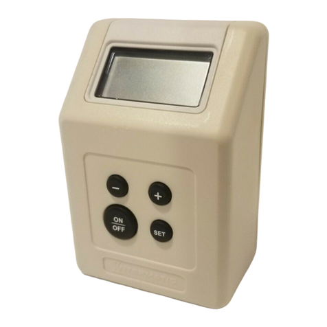
Seametrics PT32 User manual

PUB -19125-1000
Page 1 of 4
General Information
PT32 Single Pulse Timer
PT33 Dual Pulse Timer
Instructions
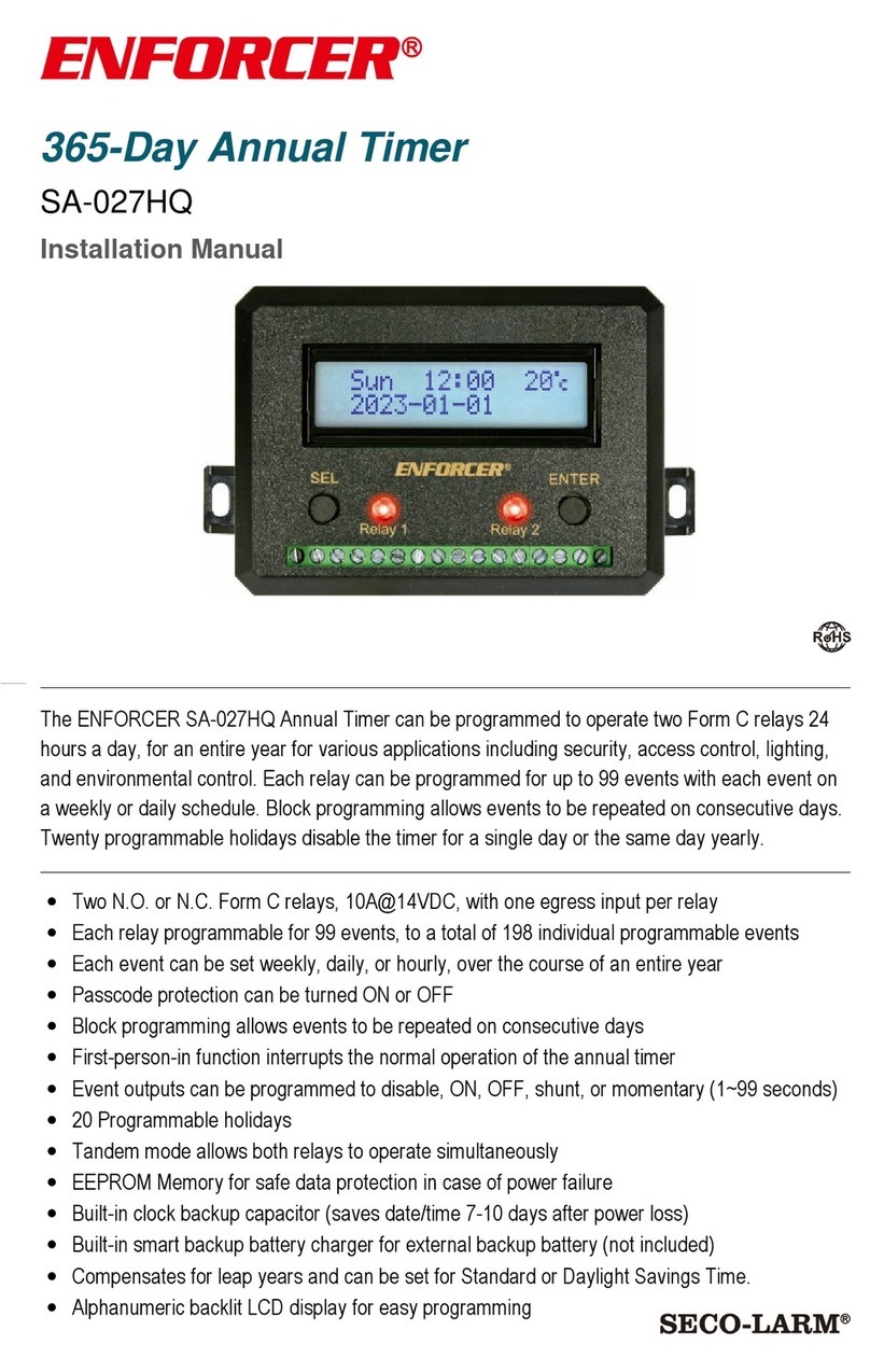
PT32 and PT33 pulse timers are designed for use with
SeaMetrics (or similar) meters and flow sensors which
produce a pulse signal. They can control metering
pumps or valves in a variety of cooling tower, boiler and
other water treatment applications. These units include
accumulators,whichcount pulsesfrom themeter. When
a preset number has been reached, output power turns
on for a set time and then the cycle repeats.
For applications requiring dual timers (typically one for
feed and one for bleed), the PT33 has two timers and
accumulatorsin oneenclosure. Inputisfrom onemeter,
but the accumulators and timers are set independently
of each other. A sequential feature locks one timer out
while the other is operating, to prevent bleed and feed
from occurring simultaneously.
A12VDC low-currentmeter loopisa standardfeature.
This can be used with brass pulse meters, as well as
most of the SeaMetrics line of insertion, turbine, and
low-flowmeters. Bothdry-contactreedswitchandsolid-
state Hall-effect sensor signals are accepted.
Specifications
Power 115 VAC
Accumulator Range 1 - 1270 counts
Timer Range 1 - 1270 seconds (21 min.)
Enclosure Glass-filled polycarbonate,
PT32 5" X 5"
PT33 5" X 7"
Max Input Frequency 500Hz (500 pulses/sec.)
Relay Contact Rating 5 A resistive at 115 VAC
Sensor Power 25 mA at 12 VDC nominal
OFF ON
TEST
INPUT
OUTPUT
PT32
ACCUMULATOR - TIMER
COUNTS
32
16
8
4
2
1Setting equals the
sum of the
switches turned "ON".
Output time equals
the sum of the
switches turned "ON".
64
32
16
8
4
2
1
SECONDS
64 This switch "ON"
multiplies by 10
This switch "ON"
multiplies by 10
OFF ON
T
I
M
E
R
A
C
C
U
M
Input and
Output Indicators
Output test and
Accumulator reset
button
Accumulator
setting switches
Timer setting
switches
Power switch
and indicator
Cover screws
and box mounting
screw holes
Three pin SeaMetrics connector
standard, strain relief optional
(order matching connector
with meter)
Power input cord
(6’ length)
Timer output
cord (7" length)
Internal 5 Amp
replaceable fuse
behind panel
PT32 Features
DISCONTINUED

Input Indicator
Separate Output test
and Accumulator
reset buttons
Accumulator #2
setting switches
Accumulator #1
setting switches
Timer #2 setting
switches
Timer #1 setting
switches
Power switch
and indicator
Cover screws
and box mounting
screw holes
Three pin SeaMetrics
connector standard-
strain relief optional
(order matching
connector with meter)
Power input cord
(6’ length)
Timer #1
output cord
(7" length)
Timer #2
output cord
(7" length)
Internal 10 Amp
replaceable fuse
OFF ON
TEST TEST
INPUT
TIMER 1 TIMER 2
PT33
DUAL
ACCUMULATOR
TIMER
OFF ON
OFF ON
Output time
(in seconds)
equals the sum
of the switches
turned "ON".
Output time
(in seconds)
equals the sum
of the switches
turned "ON".
This switch "ON"
multiplies by 10
T
I
M
E
R
1
64
32
16
8
4
2
1
This switch "ON"
multiplies by 10
32
64
16
8
4
2
1Setting equals
the sum of
the switches
turned "ON".
This switch "ON"
multiplies by 10
A
C
C
U
M
132
64
16
8
4
2
1Setting equals
the sum of
the switches
turned "ON".
This switch "ON"
multiplies by 10
A
C
C
U
M
2
T
I
M
E
R
2
Separate Output
Indicators
Mounting. Use a secure surface which will accept
screws. To gain access to the mounting screw holes,
remove the front clear cover. Mounting screw holes are
at the four corners, under the cover screws. Using the
box or enclosed template, mark centers of these holes
witha pencilanddrill. Finally,insert theenclosed screws
through the four corner holes and tighten.
Terminal Access. It is not normally necessary to ac-
cess terminals, since all connections can be made ex-
ternally. However, conduit connection requires the front
plate to be removed to reach the terminals. See Con-
nections diagram.
Connect the Meter. Standard units use a meter con-
nector. The mating half of this three-pin “SeaMetrics”
connector can be ordered preinstalled on the end of the
meter cable, or can be ordered as a separate item. See
diagram for pin numbers. Plug in the connector and
secure the threaded locking ring.
Connect Power. A power cord is provided standard.
Connect by plugging in to any grounded outlet. See
Connections diagram for conduit connection.
Connect the Load. On standard units, a short pigtail
cord with receptacle is provided for connection of a 115
VAC load. The unit can also be hard-wired if necessary.
See Connections diagram.
Pin Numbers for Connector - Field Installation
2
3
1
INPUT CONNECTOR
1 POWER GND
2 INPUT SIGNAL
3 POWER OUTPUT +12VDC
TO CONNECTOR PIN 1
TO CONNECTOR PIN 1
TO CONNECTOR PIN 2
TO CONNECTOR PIN 2
TO CONNECTOR PIN 3
BLACK
WHITE
RED
ME, IP, WT FLOW METER
MR METER (or other dry contact)
2 of 4
PT33 Features
Installation
DISCONTINUED

Setting
The DIP switches under the front clear cover are used
for accumulator and timer settings. As the front plate
states,thesetting isthe sumofthe numberedswitches
turned on. Any number from one to 127 can be set.
The multiply-by-ten switch must be used for numbers
from 130 to 1,270.
The easiest way to set a number is to begin with the
largest number which is less than the target, then add
smaller numbers until the target is reached. See illus-
tration at right.
Example 1: The desiredaccumulatorcountis 12.First
turn on the 8 switch, followed by the 4.
(8 + 4 = 12)
Example 2: The desired time is three minutes (180
seconds). Use 16 and 2 to set 18, then use the multi-
ply-by-ten switch to get 180.
COUNTS
32
16
8
4
2
1
64
32
16
8
4
2
1
SECONDS
64
OFF ON
T
I
M
E
R
A
C
C
U
M
12 counts
180 seconds
This switch "ON"
multiplies by 10
This switch "ON"
multiplies by 10
Example 1
Example 2
3 of 4
GND
SIGNAL
EXTERNALLY-PACED
METERING PUMP
DRY CONTACT
TYPE METER (MR,WPR)
GND
GND
SIGNAL
SIGNAL
+12 VDC
+12 VDC
PUMP+
SOLID STATE TYPE
METER (ME,IP,WT)
SOLID STATE TYPE
METER (ME,IP,WT)
PT32 CONNECTIONS DIAGRAM
Ground
Signal
Pump +
5 AMP AGC FUSE
110 VAC
INPUT
1
10
V
AC
OUTPUT
Hot Normally Closed
Hot Normally Open
Neutral
Ground + 12 VDC
Neutral
Ground
Hot
PT33 CONNECTIONS DIAGRAM
Hot
Neutral
Ground
High Flow Relay
NC NO N G NC NO N G
Hot Normally Closed
Hot Normally Open
Neutral
Ground
Ground
Neutral
Hot Normally Open
Hot Normally Closed
110 VAC Input
Low Flow Relay
JP1
For Sequential timer operation,
remove jumper and replace to
connect these two pins.
JP2
JP2
JP1
DISCONTINUED

Operation
Test for Proper Operation
·Turn the power switch to ON. The power indicator
should light.
·Set a short time. Then press the TEST button. The
TIMER indicator should light and stay on for the length
of time set.
·Whenthe meterisoperating,theINPUT indicatorshould
light periodically. Note that at low flow rates or low pulse
rates (such as 100 G/P) there may be a considerable
interval between inputs.
Changing Settings
When a time or count setting is changed, it is necessary
to reset to the new number. This can be done by press-
ing the test button, turning power off and back on, or by
simply waiting for a new count or time cycle to begin.
PT33 Timer Operation
Standard operation of PT33 timers is independent, and
if the accumulators are set to different numbers the
timers will operate at different times. However, if accu-
mulator settings are the same, the timers will operate
simultaneously. If this is undesirable, the unit can be
factory or field-set for sequential operation (see con-
nections diagram, p.3). This means that the two timers
will never come on at the same time. Timer #2 will wait
until timer #1 is finished before operating.This feature
is set by a jumper. It can also be field-set by removing
the front panel and moving a jumper into the appropri-
ate position.
Troubleshooting and Repair
If the unit fails to work properly, first check for power. If
power indicator fails to light when the power switch is
on, either there is no power to the unit or a fuse has
blown. Remove the front panel to change the fuse. For
the PT32, use a 3AG-5A-SB fuse. The PT33 requires a
3AG-10A-SB.
How to Determine Accumulator Setting(s):
20419 80th Ave. So., Kent WA. 98032 USA
Phone: 253-872-0284 Fax: 253-872-0285
www.seametrics.com 1-800-975-8153
4 of 4
If the meter pulses once every gallon,
set the accumulator for the number of gallons desired
betweentimercycles. For meterswith multiplepulses
per gallon, multiply the desired number of gallons by
the pulses per gallon. For meters with multiple gal-
lonsbetweenpulses, dividethe desired gallonsby the
gallons per pulse.
Example:
The goal is one timer output every 60 gallons. The
meter has a 5 gallons per pulse (G/P) output.
60 gallons
5 gallons/pulse = 12 (accumulator setting)
The other common problems are incorrect setting and
lack of meter input. Double check to be sure that the
desired number has been set, particularly the position
ofthe multiply-by-tenswitch. Meterinputcanbe checked
by watching for the INPUT indicator to light.
HowTo DetermineTimer Setting(s). The timer set-
ting is based on the desired amount of chemical to be
fed or water to be bled, and is specific to the pump,
valve, etc. being used. When calculating the time be
sure it isn’t more than the expected time between
cycles, to avoid overlapping. Check by calculating:
Cycle Size (Gallons)
Max. Flow Rate (GPM) = min. between cycles
x 60 = sec. between cycles
PT32 and PT33 timers are not designed for field repair.
Any circuit board work must be done at the factory.
Please obtain a returned material authorization (RMA)
number from the factory or your distributor before re-
turning your unit.
DISCONTINUED
This manual suits for next models
1
Other Seametrics Timer manuals
