Seametrics PT35 User manual

LT-10018-A
Page 1 of 4
PT34 Single PulseTimer
PT35 Dual PulseTimer
Instructions
General Information
The PT34 and PT35 digital counter-timers are designed
to be used with SeaMetrics (or similar) meters and flow
sensors which produce a pulse signal.They are typically
used in water treatment and chemical dosing applica-
tions, most often in cooling towers and boilers.The first
function of these units is the accumulator, which counts
pulses from the meter.When a preset number has been
reached, output power turns on for a set time, and then
the cycle repeats.
For applications requiring dual timers (typically, one
chemical feed and one water bleed) the PT35 has dual
accumulators and timers.Input is from a single meter or
flow sensor, but the accumulators and timers are set in-
dependently of each other.A sequential function can be
selected to lock one timer out while the other is operat-
ing.This prevents feed and bleed from occurring simul-
taneously.
A 12 VDC low-current meter loop is standard.This can
be used with dry contact meters, as well as contacting-
head meters with solid-state pickups (SeaMetrics ME
meters) or insertion flow sensors (SeaMetrics IP line).
Specifications
Power 115 VAC
Sensor Power 12 VDC
Enclosure 5" x 7" polycarbonate
Accumulator Range 1 - 9,999 pulses
Timer Range 1 - 9,999 seconds
Maximum Input Frequency 1000 Hz
Relay Contact Rating 5 A resistive @ 115
VAC, or 1/4 HP
Temperature 32º-130º F (0º-55º Cº)
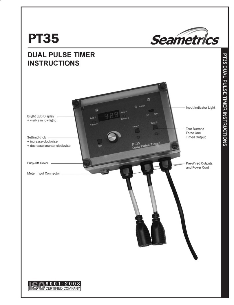
INPUT INDICATOR LIGHT
EASY-OFF COVER TEST BUTTONS
FORCE ONE
TIMED OUTPUT
PRE-WIRED OUTPUTS
AND POWER CORD
METER INPUT CONNECTOR
SETTING KNOB
+ increase clockwise
+ decrease counter-clockwise
BRIGHT LED DISPLAY
+ visible in low light
ARCHIVED

2
3
1
INPUT CONNECTOR
1 POWER GND
2 INPUT SIGNAL
3 POWER OUTPUT +12VDC
TO CONNECTOR PIN 1
TO CONNECTOR PIN 1
TO CONNECTOR PIN 2
TO CONNECTOR PIN 2
TO CONNECTOR PIN 3
BLACK
WHITE
RED
ME, IP, WT FLOW METER
MR METER (or other dry contact)
2 of 4
Installation
Mounting. Use a secure surface which will accept
screws. To gain access to the mounting screw holes,
removethefrontclear coverbyuseofthethumbscrews.
Mounting holes are at the four corners, under the cover.
Using the box as a template, mark the centers of the
holes with a pencil and drill. Insert screws through the
four corner holes and tighten.
Terminal Access. It is not normally necessary to ac-
cess the terminals, since the units come pre-wired for
external pigtail connection.However, terminals are pro-
vided internally for conduit connection. To reach these
terminals, remove the metal front plate after loosening
the four screws which hold it on.Terminals are behind
the plate.
Connect the Meter. Standardunitsprovidea metercon-
nector.The mating half of this "SeaMetrics connector"
can be ordered pre-installed on any SeaMetrics meter
orflowsensor, or a cablewith connector can be ordered
as a separate item, part no. 12050. If no connector is
immediately available, any wire ends can be connected
using the terminals inside (see "Terminal Access",
above).
Connect the Load. On standard units, a short pigtail
cord with receptacle is provided for connection of a 115
VAC load.The unit can be hard-wired if necessary, us-
ing the terminals inside.
Connect Power. A power cord is provided. connect by
plugginginto anystandardgroundedoutlet.(See "Con-
nections Diagram" for conduit connection.)
Setting
Using the thumb screws, remove the front cover. Press
the SET button. The green ACC (accumulator) light at
the upper left corner of the display will begin blinking,
indicating that the accumulator is ready to be set. Turn
the knob clockwise to increase or counter-clockwise to
decreaseuntilthe desirednumberisreached.Thenpress
SET again. The red TIMER indicator will light. Set the
desired time.For a PT 35, repeat the process to set ac-
cumulator 2 and timer 2.Press SET again to get the dis-
play "SEq" (sequential).Turning the knob in either direc-
tion will switch from "SEq" to "nSEq" (non-sequential).
Sequential operation prevents the timer 2 output from
operating while timer 1 is on, so that chemical feed does
not occur during bleed.Non-sequential operation allows
either timer to operate immediately when its count is
reached.
One more press of the SET button returns the unit to
normal operation.
Pin Numbers for Connector - Field Installation
HowTo Determine Accumulator Setting(s):
If the meter pulses once every gallon, set the
accumulator for the number of gallons desired
betweentimer cycles. Formeterswithmultiplepulses
per gallon, multiply the desired number of gallons by
the pulses per gallon. For meters with multiple
gallons between pulses, divide the desired gallons
by the gallons per pulse.
Example:
The goal is one timer output every 60 gallons. The
meter has a 5 gallons per pulse (G/P) output.
60 gallons
5 gallons/pulse = 12 (accumulator setting)
HowTo DetermineTimer Setting(s).
The timer setting is based on the desired amount of
chemical to be fed or water to be bled, and is
specific to the pump, valve, etc. being used. When
calculating the time be sure it isn’t more than the
expected time betweencycles,to avoidoverlapping.
Check by calculating:
Cycle Size (Gallons)
Max.Flow Rate (GPM) = min.between cycles
x 60 = sec. between cycles
ARCHIVED

3 of 4
Operation
Test forTimer Output.To test the timer (either timer in
the case of the PT35) press the "TEST 1" or "TEST 2"
button. The red output indicator should light, and re-
main on for the previously-set number of seconds.
Standard Operation. After setting (when the unit has
returned to normal operation, indicated by no blinking
indicators) any display can be selected at any time by
turning the knob.For the PT35, turning the knob clock-
wise causes clockwise rotation among the indicator
lights. Stop turning the knob after arriving at the de-
sired display. This is the display that will remain until
another display is selected.
PT34 CONNECTIONS DIAGRAM
PT35 CONNECTIONS DIAGRAM
GND
SIGNAL
EXTERNALLY-PACED
METERING PUMP
DRY CONTACT
TYPE METER (MR,WPR)
GND
GND
SIGNAL
SIGNAL
+12 VDC
+12 VDC
PUMP+
SOLID STATE TYPE
METER (ME,IP,WT)
SOLID STATE TYPE
METER (ME,IP,WT)
INPUT CONNECTIONS
NO NC N G
Ground
Neutral
Hot Normally Closed
Hot Normally Open
H V G
P
G
S
V
OUTPUT
Ground
Neutral
Hot
3AG-5A-SB Fuse
POWER
Ground
Neutral
Hot
NO NC N G NO NC N G
Hot Normally Open
Hot Normally Closed
Neutral
Ground
Ground
Neutral
Hot Normally Closed
Hot Normally Open
H V G
P
G
S
V
OUTPUT 1
OUTPUT 2
3AG-10A-SB Fuse
POWER
ARCHIVED

20419 80th Ave. So., Kent WA. 98032 USA
Phone: 253-872-0284 Fax: 253-872-0285
www.seametrics.com 1-800-975-8153
4 of 4
Troubleshooting and Repair
If the unit fails to work properly, first check for a display.
If the Off/On switch is fully in the On position and the
display is not lighted, the unit probably does not have
power. Check for power at the cord or outlet the unit is
plugged into.
If there is power, the switch is on, and there is no dis-
play, remove the front panel (after loosening the four
screws which hold it in place) and check the fuse.If the
fuse is blown, replace it with a 3AG-5A-SB fuse (PT34)
or a 3AG-10A-SB (PT35).
If there is power, the switch is on, there is no display,
and the fuse is good, the problem is at a component
level on the printed circuit board, and the unit will need
to be returned for repair. Contact your distributor, if
known,otherwisecontactthe factory at 1-800-975-8153.
Ifthedisplay is lighted buttheunitseemstobefunction-
ing abnormally, check the following:
1) Is there input from the meter? If so, the "Input" indica-
tor should light periodically when there is flow through
the meter.(Note that a meter can be set for a low pulse
rate, 100 gallons per pulse, for instance, and therefore
several minutes can pass between inputs.)
2) Is the unit set properly? Press the "Set" button to see
each setting.
3) Is the output properly connected to its load (pump or
valve for example)? Press the appropriate "Test" button
toforcean output and check.Each test buttonis located
directly above the output it forces.
If the unit appears to be functioning normally and the
test button causes the timer indicator to light, but the
appropriate output does not actually become powered,
the probable cause is a relay failure.Although rare, this
is possible, and the unit will need to be returned for
relay replacement.
ARCHIVED
This manual suits for next models
1
Other Seametrics Timer manuals
