Seametrics AO55 User manual
LT-10604-A
Page 1 of 4
AO55 Blind Analog
Transmitter Instructions
Features
0
9
8
7
6
5
4
3
2
1
0
9
8
7
6
5
4
3
2
1
0
9
8
7
6
5
4
3
2
1
0
9
8
7
6
5
4
3
2
1
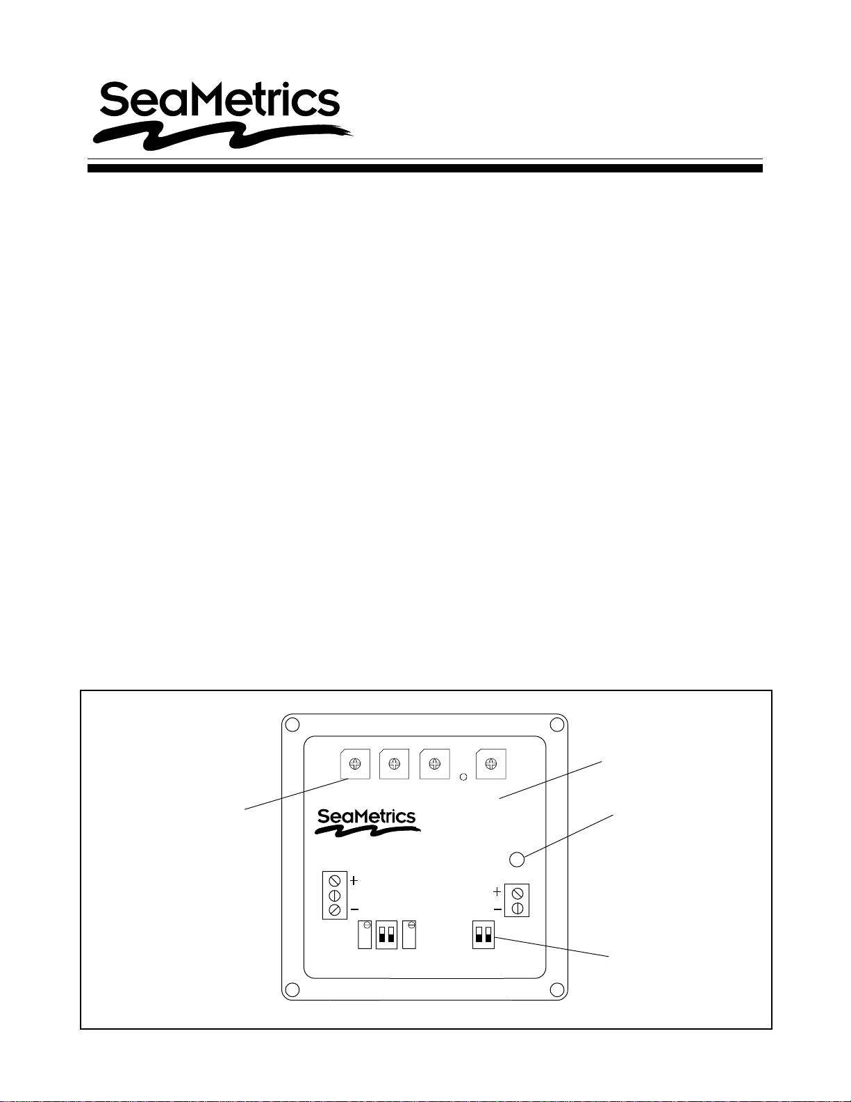
AO55
Frequency
Power
Sensor
4-20 mA
General Information
The SeaMetrics AO55 is a blind (non-indicating)
4-20 mA transmitter, designed for use with almost all
SeaMetrics flow sensors. It accepts a pulse frequency
input from the flow sensor, and converts this input into a
continuousanalogoutputsignal.Powerforthetransmitter
is taken from the current loop itself, so only two wires
arerequired.Thedigital design makesitpossibletospan
the unit in the field without tools.The frequency at which
20 mA is desired is entered on a set of rotary switches,
and an internal microcontroller automatically scales all
other values accordingly. An additional benefit of the
microcontroller is its ability to average inputs, for
smoothing of the output signal.The degree of averaging
can be selected in the field, from 2 to 16 seconds.
For maximum environmental protection, the electronic
components are encased in a special semi-flexible
urethane potting material. The housing is cast from
aluminum and fuse-coated. The clamshell housing is
connecteddirectly to theflowsensoror,inthe wallmount
version, provided with mounting feet.
The AO55 will operate on a relatively wide range of
current loop voltages, 12 to 36 VDC. However, lower
voltages limit the load that can be applied to the loop
without distortion of the signal. (See chart on page 4 if
there is a question regarding voltage vs.load.) A built-in
power regulator supplies the appropriate power to the
flow sensor.
Typical applications for this transmitter are telemetry (or
SCADA), distributed control systems, programmable
controllers, data logging, and chart recording.
Specifications
Power 12 - 36 VDC
Temperature 32°- 130°F (0°- 55°C)
Input open-collector solid-
state
Minimum Frequency 10 Hz (@20 mA)
Maximum Frequency 999.9 Hz
Output proportional 4-20 mA
Frequency Setting 4 rotary DIP switches
Input Averaging 2 - 16 seconds
(switch selectable)
ResponseTime 2-60 seconds
90% of full scale
(dependent on input
averaging)
Digital span setting Loop indicator light
Potted module for
moisture protection
Field-set
averaging time

= 154.42
Frequency Setting Example
An IP 81 with AO55M is installed in a 2" PVC line.
The maximum flow for this installation is estimated
to be about 150 GPM.To be on the safe side, a flow
rate of 170 GPM is selected as the full-scale
maximum, the flow at which the current loop will
register 20 mA.
The model/serial label on the SeaMetrics fitting
reads "k = 54.50"
2 of 4
Installation
Mounting.The wall mount style (AO55W) is the only
housing which needs to be mounted, since the meter
mount (AO55M) is already physically connected to the
flowsensor.The AO55W comeswithmounting feet and
requires four screws to attach it to any stable surface.
Connection. On either style of housing, the upper
portion must be removed to make connections.Use a
standard hex wrench (5/32" or 4 mm) to loosen the
screws, then remove the upper half.The connections
are made to terminal blocks in this upper half, which
contains the potted electronics.Note that the terminal
blocks are a removable style, and can be unplugged
and plugged back in for convenience.
Look at the connections diagram before connecting to
the current loop.The only connections required on an
AO55Marethe positiveandnegative loop connections.
On an AO55W, the sensor must also be connected,
since it is remote from the transmitter.Be careful to
follow the color coding of the three flow sensor wires in
order to establish the correct polarity.Incorrect polarity
can damage the sensor.
Settings
Setting Frequency.The AO55 converts a train of off/
on pulses from the flow sensor into a continuous
milliamp signal.This signal ranges from 4 milliamps at
zero flow to 20 milliamps at the desired maximum flow.
This desired maximum is determined by the user, and
then entered as a frequency.
Todetermine the frequency setting, follow these steps:
1) Decide what flow rate should represent the top of
thescale.This isordinarilythe maximumexpected flow
or a value just above it, in gallons per minute.
2) Determine the k-factor of the flow sensor.This will
be on the model/serial label of the fitting in the case of
anyTX or IP 80-series (81 or 82).For an IP or TX 100/
200 series (101, 201, 115, 215) it will be on a chart in
the instruction manual.For any S-series flow sensor
(SPX, SPT, SEB) it will be on the model/serial label.
The k-factor is simply the number of pulses the flow
sensor produces per gallon of flow.It is determined by
a flow test, except in the case of the 100/200 series,
which are adjustable for a wide range of pipe sizes.
3) Calculate frequency, using this formula:
K-FACTOR X TOP FLOW (GPM)
60
Enter this frequency,using the four rotary switches
marked frequency.Note the decimal point between the
third and fourth switches.
Example: 154.4
Turn rotary switch pointer to the desired digit.
0
9
8
7
6
5
4
3
2
1
0
9
8
7
6
5
4
3
2
1
0
9
8
7
6
5
4
3
2
1
0
9
8
7
6
5
4
3
2
1
AO55
Frequency
Power
Sensor
4-20 mA
154.4
Rounding to one decimal point, 154.4 is entered on
the rotary switches (154.4).
54.50 x 170
60

Connections
3 of 4
Setting AveragingTime
Setting Averaging Time. For most applications, this
step can be ignored. The unit comes with a setting
alreadyinplacewhichwillwork fineformostapplications.
However, for applications in which a particularly steady
output signal is desired, or in large pipe, a larger
averaging period may be desirable. Note however that
the averaging period requires a tradeoff, since a longer
averaging period implies a slower response time. If
steady signal is more important than fast response,
increasethe averaging time asdesired.Seethediagram
for the switch positions and their corresponding times.
Checking Calibration
Normally itshouldnot benecessaryto checkcalibration,
since the digital design of this unit virtually eliminates
drift. However, there are two types of calibration check
which can be performed. Look at the "Connections"
diagram to locate the 4 and 20 mA force switches. To
force the 4 mA output, put its switch in the up position.
Check the current output at the Power terminals, and if
necessarytrimto 4.00 mAusingthe appropriatetrimpot.
Return the switch to the down position, and repeat the
process with the 20 mA switch.
0
9
8
7
6
5
4
3
2
1
0
9
8
7
6
5
4
3
2
1
0
9
8
7
6
5
4
3
2
1
0
9
8
7
6
5
4
3
2
1
AO55
Frequency
Power
Sensor
4-20 mA
UP
DOWN
Seconds
2
4
8
16
S1
down
down
up
up
S2
down
up
down
up S2
S1
0
9
8
7
6
5
4
3
2
1
0
9
8
7
6
5
4
3
2
1
0
9
8
7
6
5
4
3
2
1
0
9
8
7
6
5
4
3
2
1
AO55
Frequency
Power
Sensor
4-20 mA
4mA Adjust
Force 4 mA
Force 20 mA
20 mA Adjust
Response time
-
+
Recording or
Control Device
12-36 VDC
Power Supply
(may be included
in control unit)
Sensor
Red
White
Black
-
Signal
+
-
+

20419 80th Ave. So., Kent WA. 98032 USA
Phone: 253-872-0284 Fax: 253-872-0285
www.seametrics.com 1-800-975-8153
4 of 4
Troubleshooting Guide
Problem Probable Cause Check First Further Test
No analog signal at
reading device Break in current loop
Dead power supply
Reversed polarity
Loop indicator light
on? Multimeter: check
voltage on power supply
Check polarity
Output stuck at 4 mA No frequency input
from flow sensor Flow sensor rotor turn
freely?
Flow sensor
connections good?
Flow sensor polarity
correct?
Terminal blocks firmly
plugged in?
With flow sensor
disconnected, use short
piece of wire to
repeatedly short
between sensor "sig" and
"-" terminals. Output mA
should rise.
mA signal doesn't
match flow rate Inadequate voltage
Wrong frequency
setting
Voltage vs. load chart
Review setting
procedure
Multimeter: check
voltage
Loop
Power
(VDC)
Load Resistance
400 600200 800 1000 1200
36
34
32
30
28
26
24
22
20
18
16
14
12
Load vs. Supply Voltage
Operating
Region
Other Seametrics Transmitter manuals


