Vega VEGABAR 86 User manual

Quick setup guide
Submersible pressure transmitter with
ceramic measuring cell
VEGABAR 86
4 … 20 mA/HART
With SIL qualication
Document ID: 46321

2
Contents
VEGABAR 86 • 4 … 20 mA/HART
46321-EN-220624
Contents
1 For your safety ......................................................................................................................... 3
1.1 Authorised personnel ....................................................................................................... 3
1.2 Appropriate use................................................................................................................ 3
1.3 Warning about incorrect use............................................................................................. 3
1.4 General safety instructions............................................................................................... 3
1.5 EU conformity................................................................................................................... 3
1.6 SILqualicationaccordingtoIEC61508.......................................................................... 4
2 Product description ................................................................................................................. 5
2.1 Conguration.................................................................................................................... 5
3 Mounting................................................................................................................................... 6
3.1 General instructions for use of the instrument .................................................................. 6
3.2 Ventilation and pressure compensation............................................................................ 6
4 Connecting to power supply................................................................................................... 8
4.1 Connecting....................................................................................................................... 8
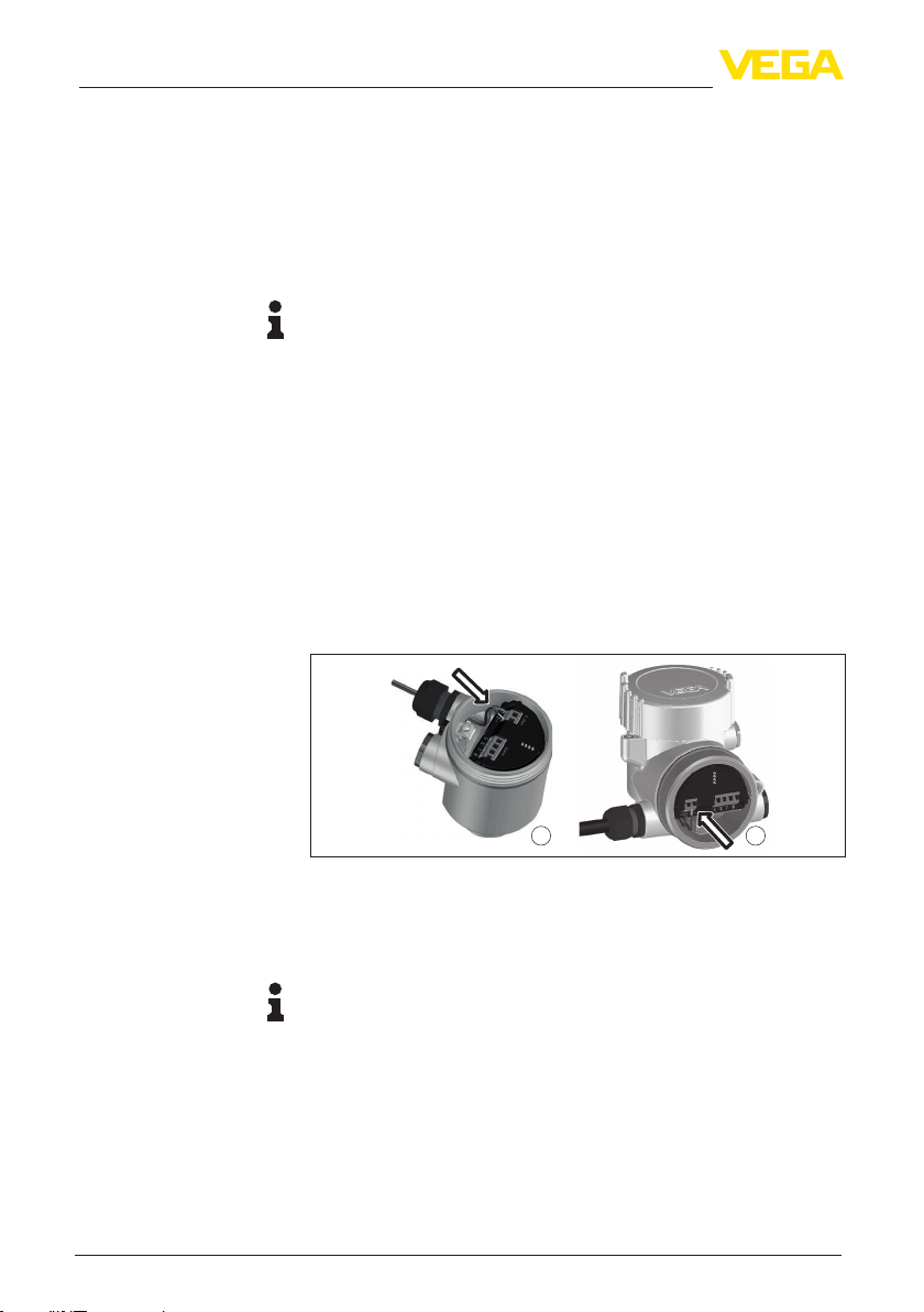
4.2 Single chamber housing................................................................................................... 9
4.3 Double chamber housing ................................................................................................. 9
5 Set up with the display and adjustment module ................................................................ 10
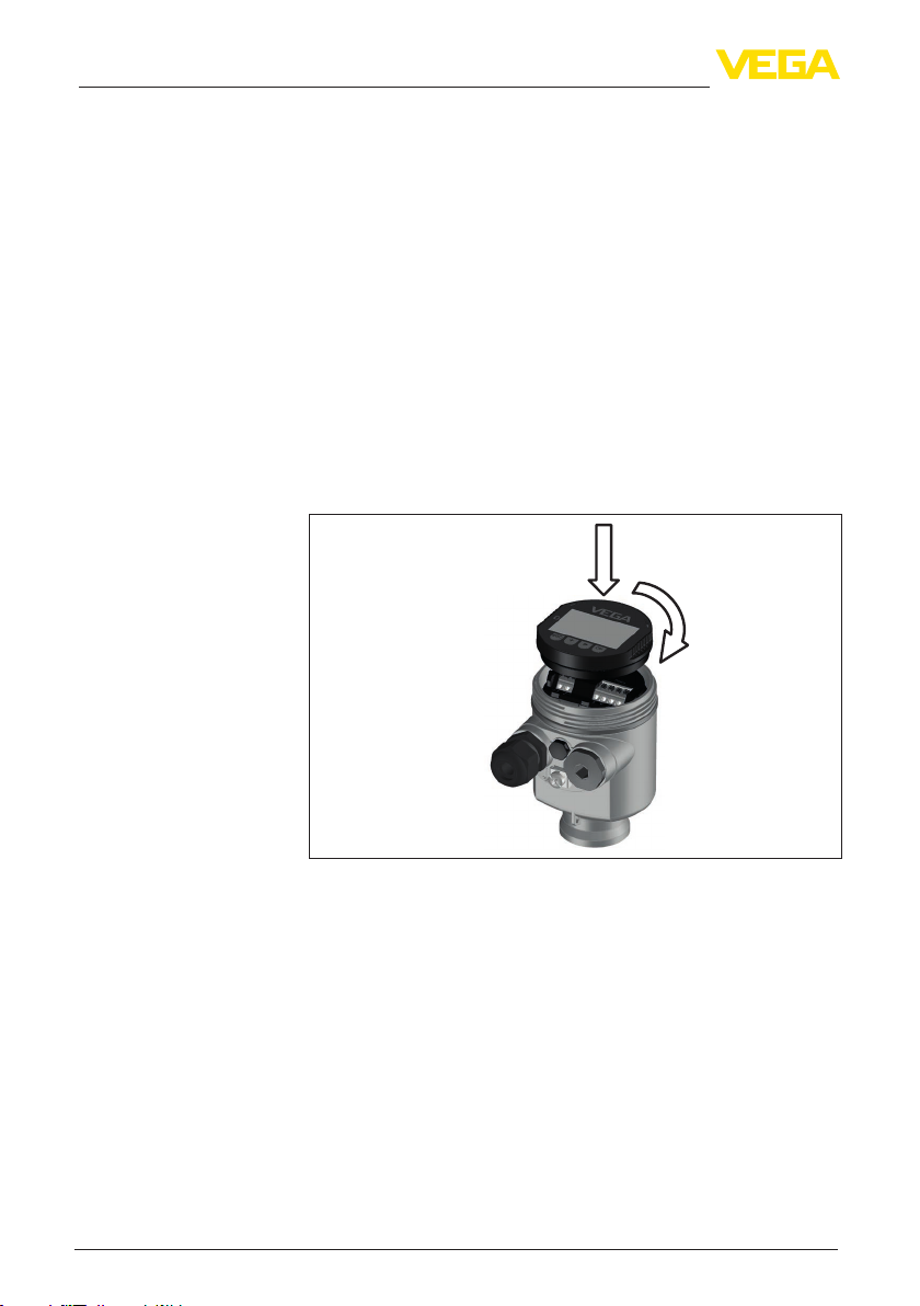
5.1 Insert display and adjustment module............................................................................ 10
5.2 Parameter adjustment .................................................................................................... 11
5.3 Menu overview ............................................................................................................... 14
6 Set up with smartphone/tablet, PC/notebook via Bluetooth ............................................. 16
6.1 Preparations................................................................................................................... 16
6.2 Connecting..................................................................................................................... 17
6.3 Sensor parameter adjustment........................................................................................ 17
7 Supplement ............................................................................................................................ 19
7.1 Technical data ................................................................................................................ 19
Information:
This quick setup guide enables quick setup and commissioning of
your instrument.
Youcanndsupplementaryinformationinthecorresponding,more
detailed Operating Instructions Manual as well as the Safety Manual
thatcomeswithinstrumentswithSILqualication.Thesemanualsare
available on our homepage.
Operating instructions VEGABAR 86 - 4 … 20 mA/HART:
Document-ID 45041
Safety Manual VEGABAR series 80 - Two-wire 4 … 20 mA/HART
with SIL qualication: Document-ID 48369
Editing status of the quick setup guide: 2022-04-20

3
1 For your safety
VEGABAR 86 • 4 … 20 mA/HART
46321-EN-220624
1 For your safety
1.1 Authorised personnel
All operations described in this documentation must be carried out
onlybytrained,qualiedpersonnelauthorisedbytheplantoperator.
Duringworkonandwiththedevice,therequiredpersonalprotective
equipment must always be worn.
1.2 Appropriate use
Model VEGABAR 86 is a pressure transmitter for level and gauge
measurement.
Youcannddetailedinformationabouttheareaofapplicationin
chapter " Product description".
Operational reliability is ensured only if the instrument is properly
usedaccordingtothespecicationsintheoperatinginstructions
manual as well as possible supplementary instructions.
1.3 Warning about incorrect use
Inappropriate or incorrect use of this product can give rise to applica-
tion-specichazards,e.g.vesseloverllthroughincorrectmounting
or adjustment. Damage to property and persons or environmental
contaminationcanresult.Also,theprotectivecharacteristicsofthe
instrument can be impaired.
1.4 General safety instructions
This is a state-of-the-art instrument complying with all prevailing
regulations and directives.The instrument must only be operated in a
technicallyawlessandreliablecondition.Theoperatorisresponsi-
ble for the trouble-free operation of the instrument. When measuring
aggressive or corrosive media that can cause a dangerous situation
iftheinstrumentmalfunctions,theoperatorhastoimplementsuitable
measures to make sure the instrument is functioning properly.
Thesafetyinstructionsinthisoperatinginstructionsmanual,thena-
tional installation standards as well as the valid safety regulations and
accident prevention rules must be observed by the user.
Forsafetyandwarrantyreasons,anyinvasiveworkonthedevice
beyond that described in the operating instructions manual may be
carried out only by personnel authorised by the manufacturer. Arbi-
traryconversionsormodicationsareexplicitlyforbidden.Forsafety
reasons,onlytheaccessoryspeciedbythemanufacturermustbe
used.
Toavoidanydanger,thesafetyapprovalmarkingsandsafetytipson
the device must also be observed.
1.5 EU conformity
ThedevicefullsthelegalrequirementsoftheapplicableEUdirec-
tives.ByaxingtheCEmarking,weconrmtheconformityofthe
instrument with these directives.

4
1 For your safety
VEGABAR 86 • 4 … 20 mA/HART
46321-EN-220624
The EU conformity declaration can be found on our homepage.
1.6 SIL qualication according to IEC 61508
The Safety Integrity Level (SIL) of an electronic system is used to as-
sess the reliability of integrated safety functions.
Fordetailedspecicationofthesafetyrequirements,multipleSIL
levelsarespeciedaccordingtosafetystandardIEC61508.Youcan
nddetailedinformationinchapter"Functional safety (SIL)" of the
operating instructions.
TheinstrumentmeetsthespecicationsofIEC61508:2010(Edi-
tion2).Itisqualiedforsingle-channeloperationuptoSIL2.The
instrument can be used homogeneously redundant up to SIL3 in
multi-channel architecture with HFT 1.

5
2 Product description
VEGABAR 86 • 4 … 20 mA/HART
46321-EN-220624
2 Product description
2.1 Conguration
Thetypelabelcontainsthemostimportantdataforidenticationand
use of the instrument:
7
8
6
4
5
2
3
1
Fig. 1: Layout of the type label (example)
1 Product code
2 Field for approvals
3 Technical data
4 Serial number of the instrument
5 QR code
6 Symbol of the device protection class
7 ID numbers, instrument documentation
8 SILidentication
The type label contains the serial number of the instrument. With it
youcanndthefollowinginstrumentdataonourhomepage:
• Product code (HTML)
• Delivery date (HTML)
• Order-specicinstrumentfeatures(HTML)
• Operatinginstructions,quicksetupguideandSafetyManualatthe
time of shipment (PDF)
• Testcerticate(PDF)-optional
Move to " www.vega.com"andenterinthesearcheldtheserial
number of your instrument.
Alternatively,youcanaccessthedataviayoursmartphone:
• Download the VEGA Tools app from the " Apple App Store" or the
" Google Play Store"
• ScantheDataMatrixcodeonthetypelabeloftheinstrumentor
• Enter the serial number manually in the app
Type label
Serial number - Instru-
ment search

6
3 Mounting
VEGABAR 86 • 4 … 20 mA/HART
46321-EN-220624
3 Mounting
3.1 General instructions for use of the instrument
Protect your instrument against moisture ingress through the following
measures:
• Use a suitable connection cable (see chapter " Connecting to
power supply")
• Tighten the cable gland or plug connector
• Lead the connection cable downward in front of the cable entry or
plug connector
Thisappliesmainlytooutdoorinstallations,inareaswherehigh
humidityisexpected(e.g.throughcleaningprocesses)andoncooled
or heated vessels.
Note:
Make sure that during installation or maintenance no moisture or dirt
can get inside the instrument.
Tomaintainthehousingprotection,makesurethatthehousinglidis
closedduringoperationandlocked,ifnecessary.
3.2 Ventilation and pressure compensation
1 2 3
6
6
6 6
6
5
4
Fig.2:Positionofthelterelement
1 Plastic, stainless steel single chamber (precision casting)
2 Aluminium - single chamber
3 Stainless steel single chamber (electropolished)
4 Plastic double chamber
5 Aluminium, stainless steel double chamber housing (precision casting)
6 Filter element
With the following instruments a blind plug is installed instead of the
lterelement:
Protection against mois-
ture
Filter element - Position

7
3 Mounting
VEGABAR 86 • 4 … 20 mA/HART
46321-EN-220624
• Instruments in protection IP66/IP68 (1 bar) - ventilation via capillar-
ies in non-detachable cable
• Instruments with absolute pressure

8
4 Connecting to power supply
VEGABAR 86 • 4 … 20 mA/HART
46321-EN-220624
4 Connecting to power supply
4.1 Connecting
The voltage supply and signal output are connected via the spring-
loaded terminals in the housing.
Connection to the display and adjustment module or to the interface
adapter is carried out via contact pins in the housing.
Information:
The terminal block is pluggable and can be removed from the
electronics.Todothis,lifttheterminalblockwithasmallscrewdriver
andpullitout.Whenreinsertingtheterminalblock,youshouldhearit
snap in.
Proceed as follows:
1. Unscrew the housing lid
2. Ifadisplayandadjustmentmoduleisinstalled,removeitbyturn-
ing it slightly to the left
3. Loosen compression nut of the cable gland and remove blind
plug
4. Removeapprox.10cm(4in)ofthecablemantle,stripapprox.
1 cm (0.4 in) of insulation from the ends of the individual wires
5. Insert the cable into the sensor through the cable entry
1 2
Fig. 3: Connection steps 5 and 6
1 Single chamber housing
2 Double chamber housing
6. Insert the wire ends into the terminals according to the wiring plan
Note:
Solidcoresaswellasexiblecoreswithwireendsleevesareinsert-
eddirectlyintotheterminalopenings.Incaseofexiblecoreswithout
endsleeves,presstheterminalfromabovewithasmallscrewdriver,
theterminalopeningisthenfree.Whenthescrewdriverisreleased,
the terminal closes again.
7. Check the hold of the wires in the terminals by lightly pulling on
them
8. Connecttheshieldingtotheinternalgroundterminal,connectthe
externalgroundterminaltopotentialequalisation
Connection technology
Connection procedure

9
4 Connecting to power supply
VEGABAR 86 • 4 … 20 mA/HART
46321-EN-220624
9. Tighten the compression nut of the cable entry gland. The seal
ring must completely encircle the cable
10. Reinsertthedisplayandadjustmentmodule,ifonewasinstalled
11. Screw the housing lid back on
Theelectricalconnectionisnished.
4.2 Single chamber housing
Thefollowingillustrationappliestothenon-Ex,Ex-iaandEx-dver-
sion.
5
12
+
( ) (-)
678
4...20mA
2
3
4
1
Fig. 4: Electronics and connection compartment - single chamber housing
1 Voltage supply, signal output
2 For display and adjustment module or interface adapter
3 For external display and adjustment unit or Secondary sensor
4 Ground terminal for connection of the cable screening
4.3 Double chamber housing
Thefollowingillustrationsapplytothenon-ExaswellastotheEx-ia
version.
5
12
+
( ) (-)
678
4...20mADisplay
2
3
4
1
Fig. 5: Connection compartment - double chamber housing
1 Voltage supply, signal output
2 For display and adjustment module or interface adapter
3 For external display and adjustment unit
4 Ground terminal for connection of the cable screening
Electronics and connec-
tion compartment
Connection compartment

10
5 Set up with the display and adjustment module
VEGABAR 86 • 4 … 20 mA/HART
46321-EN-220624
5 Set up with the display and adjustment
module
5.1 Insert display and adjustment module
The display and adjustment module can be inserted into the sensor
andremovedagainatanytime.Youcanchooseanyoneoffourdier-
ent positions - each displaced by 90°. It is not necessary to interrupt
the power supply.
Proceed as follows:
1. Unscrew the housing lid
2. Place the display and adjustment module on the electronics in the
desired position and turn it to the right until it snaps in.
3. Screw housing lid with inspection window tightly back on
Disassembly is carried out in reverse order.
Thedisplayandadjustmentmoduleispoweredbythesensor,anad-
ditional connection is not necessary.
Fig. 6: Installing the display and adjustment module in the electronics compart-
ment of the single chamber housing

11
5 Set up with the display and adjustment module
VEGABAR 86 • 4 … 20 mA/HART
46321-EN-220624
1 2
Fig. 7: Installing the display and adjustment module in the double chamber
housing
1 In the electronics compartment
2 In the connection compartment
Note:
Ifyouintendtoretrottheinstrumentwithadisplayandadjustment
moduleforcontinuousmeasuredvalueindication,ahigherlidwithan
inspection glass is required.
5.2 Parameter adjustment
AparameterchangewithSILqualiedinstrumentsmustalwaysbe
carried out as follows:
• Unlock adjustment
• Change parameters
• Lockadjustmentandverifymodiedparameters
Thisensuresthatallmodiedparametershavebeendeliberately
changed.
Unlock adjustment
The instrument is shipped in locked condition.
Topreventunintentionalorunauthorizedadjustment,theinstrument
is protected (locked) against all parameter changes while in normal
operating condition.
For each parameter change you have to enter the PIN of the instru-
ment.Indeliverystatus,thePINis"0000".
Change parameters
Youcanndadescriptionbelowtherespectiveparameter.
Operating sequence

12
5 Set up with the display and adjustment module
VEGABAR 86 • 4 … 20 mA/HART
46321-EN-220624
Lock adjustment and verify modied parameters
Youcanndadescriptionbelowtheparameter"Setup - Lock adjust-
ment".
1. Go to the menu " Setup" via the display and adjustment module.
2. In this menu item you activate/deactivate the slave sensor for
electronicdierentialpressureandselecttheapplication,e.g.
level
3. Select in the menu item " Units" the adjustment unit of the instru-
ment,e.g."bar".
4. Dependingontheapplication,carryouttheadjustmente.g.inthe
menu items " Min. adjustment" and " Max. adjustment".
VEGABAR 86 always measures pressure independently of the pro-
cess variable selected in the menu item " Application".To output the
selectedprocessvariablecorrectly,anallocationoftheoutputsignal
to 0 % and 100 % must be carried out (adjustment).
Duringadjustment,thepressureisenterede.g.forthelevelwithfull
andemptyvessel,seefollowingexample:
Change setup parameters
Parameterization example

13
5 Set up with the display and adjustment module
VEGABAR 86 • 4 … 20 mA/HART
46321-EN-220624
2
1
100%
0%
2 m
(78.74
")
Fig. 8: Parameter adjustment example Min./max. adjustment, level measure-
ment
1 Min. level = 0 % corresponds to 0.0 mbar
2 Max. level = 100 % corresponds to 196.2 mbar
Ifthesevaluesarenotknown,anadjustmentwithllinglevelsofe.g.
10%and90%isalsopossible.Bymeansofthesesettings,thereal
llingheightisthencalculated.
Theactualproductlevelduringthisadjustmentisnotimportant,
becausethemin./max.adjustmentisalwayscarriedoutwithout
changing the product level.These settings can be made ahead of
time without the instrument having to be installed.
With this menu item you safeguard the sensor parameters against
unauthorizedorunintentionalmodications.
Todetectparameterizationerrorsreliably,safety-relevantparameters
mustbeveriedbeforesavingthemintotheinstrument.
1. Enter PIN
Indeliverystatus,thePINis"0000".
2. Character string comparison
You then have to carry out the character string comparison. This is
used to check the character presentation.
3. Serial number acknowledgement
Afterwardsyouconrmthattheserialnumberofyourinstrumentwas
carried over correctly. This is used to check device communication.
4. Verify parameters
Conrmthemodiedvaluesoneaftertheother.
If the described process of parameter adjustment was run through
completelyandcorrectly,theinstrumentwillbelockedandhence
ready for operation.
Lock adjustment

14
5 Set up with the display and adjustment module
VEGABAR 86 • 4 … 20 mA/HART
46321-EN-220624
5.3 Menu overview
The following tables show the adjustment menu of the instrument.
Dependingontheinstrumentversionorapplication,allmenuitems
maynotbeavailableorsomemaybedierentlyassigned.
The safety-relevant menu items having to do with functional safety
according to IEC 61508 (Edition 2) are marked with " SIL".
Setup
Menu item Parameter Default value
Measurement loop name 19 alphanumeric characters/special
characters
Sensor
Application (SIL) Application Level
Secondarysensorforelectronicdieren-
tial pressure
Deactivated
Units Adjustmentunit(m,bar,Pa,psi…user-
dened)
mbar (with nominal measuring range
≤400mbar)
bar (with nominal measuring ranges
≥1bar)
Temperatureunit(°C,°F) °C
Position correction (SIL) 0.00 bar
Adjustment (SIL) Zero/Min. adjustment 0.00 bar
0.00 %
Span/Max.adjustment Nominal measuring range in bar
100.00 %
Damping (SIL) Integration time 1 s
Linearisation Linear,cylindricaltank,…user-dened Linear
Current output (SIL) Current output - Mode
Outputcharacteristics:4…20mA,
20 … 4 mA
4 … 20 mA
Failuremode:≤3.6mA,≥20mA,last
measured value
≤3.6mA
Currentoutput-Min./Max.
Min.current:3.8mA,4mA 3.8 mA
Max.current:20mA,20.5mA 20.5 mA
Lock adjustment (SIL) Blocked,released Last setting
Display
Menu item Default value
Menu language No reset
Displayed value 1 Pressure
Displayed value 2 Ceramic measuring cell: Measuring cell temperature in °C
Metallic measuring cell: Electronics temperature in °C

15
5 Set up with the display and adjustment module
VEGABAR 86 • 4 … 20 mA/HART
46321-EN-220624
Menu item Default value
Backlight Switchedo
Diagnostics
Menu item Parameter Default value
Device status No reset
Peak value Pressure Current pressure measured value
Pointer function temp. Temperature Actual measuring cell and electronic tem-
perature
Simulation Measured value Pressure
Simulations Not active
Proof test No reset
Additional adjustments
Menu item Parameter Default value
Date/Time No reset
Reset Deliverystatus,basicsettings No reset
Copy instrument settings Readfromsensor,writeintosensor No reset
Scaling Scalingsize Volume in l
Scaling format 0 % corresponds to 0 l
100 % corresponds to 0 l
Without decimal positions
Current output (SIL) Current output - Meas. variable Lin. percent - Level
Current output - Adjustment 0 … 100 % correspond to 4 … 20 mA
Current output 2 Current output - Meas. variable Measuring cell temperature
Current output - Adjustment 0 … 100 % correspond to 4 … 20 mA
HART mode HARTaddress,currentoutput Address00,analoguecurrentoutput
Special parameter (SIL) Service-Login No reset
Info
Menu item Parameter
Device name VEGABAR 86
Instrument version Hardware and software version
Factory calibration date Date
Sensor characteristics Order-speciccharacteristics

16
6Setupwithsmartphone/tablet,PC/notebookviaBluetooth
VEGABAR 86 • 4 … 20 mA/HART
46321-EN-220624
6 Set up with smartphone/tablet, PC/
notebook via Bluetooth
6.1 Preparations
Make sure that the Bluetooth function of the display and adjustment
moduleisactivated.Forthis,theswitchonthebottomsidemustbe
set to " On".
1
On
O
Fig. 9: Activate Bluetooth
1 Switch
On = Bluetooth active
O= Bluetoothnotactive
The security concept of Bluetooth operation absolutely requires that
the default setting of the sensor PIN be changed.This prevents unau-
thorizedaccesstothesensor.
The default setting of the sensor PIN is " 0000". First of all you have
tochangethesensorPINintheadjustmentmenuofthesensor,e.g.
to " 1111":
1. Gotosetupviatheextendedoperation
2. Lock operation by changing sensor PIN
3. Enable operation again by entering the sensor PIN once more
Activate Bluetooth
Change sensor PIN

17
6Setupwithsmartphone/tablet,PC/notebookviaBluetooth
VEGABAR 86 • 4 … 20 mA/HART
46321-EN-220624
Sensor adjustment via the display/adjustment module or PACTware/
DTM by means of VEGACONNECT is thus released again. For ac-
cess(authentication)withBluetooth,thechangedPINisstilleective.
Note:
Bluetooth access can only be established if the current sensor PIN
diersfromthedefaultsetting"0000". It is possible both when the
adjustment is unlocked and when it is locked.
6.2 Connecting
Smartphone/Tablet
Start the adjustment app and select the function "Setup". The smart-
phone/tablet searches automatically for Bluetooth-capable instru-
ments in the area.
PC/Notebook
Start PACTware and the VEGA project assistant. Select the device
search via Bluetooth and start the search function.The device auto-
matically searches for Bluetooth-capable devices in the vicinity.
The message " Instrument search running" is displayed. All devices
found are listed in the operating window. The search is automatically
continued continuously.
Select in the device list the requested device.The message " Con-
necting" is displayed.
Fortherstconnection,theoperatingdeviceandthesensormust
authenticateeachother.Aftersuccessfulauthentication,thenextcon-
nection functions without authentication.
Forauthentication,enterinthenextmenuwindowthe4-digitsensor
PIN.
6.3 Sensor parameter adjustment
Thesensorparameterizationiscarriedoutviatheadjustmentappon
the smartphone/tablet or the DTM on the PC/notebook.
Preparations
Connecting
Authenticate

18
6Setupwithsmartphone/tablet,PC/notebookviaBluetooth
VEGABAR 86 • 4 … 20 mA/HART
46321-EN-220624
Fig. 10: Example of an app view - Setup sensor adjustment
App view

19
7 Supplement
VEGABAR 86 • 4 … 20 mA/HART
46321-EN-220624
7 Supplement
7.1 Technical data
Note for approved instruments
The technical data in the respective safety instructions which are included in delivery are valid for
approvedinstruments(e.g.withExapproval).Thesedatacandierfromthedatalistedherein,for
exampleregardingtheprocessconditionsorthevoltagesupply.
All approval documents can be downloaded from our homepage.
Electromechanical data - version IP66/IP67 and IP66/IP68 (0.2 bar) 1)
Options of the cable entry
ƲCable entry M20x1.5;½NPT
ƲCable gland M20x1.5,½NPT(cableøseebelowtable)
ƲBlind plug M20x1.5;½NPT
ƲClosing cap ½NPT
Material cable gland/Seal insert Cable diameter
5 … 9 mm 6 … 12 mm 7 … 12 mm 10 … 14 mm
PA/NBR ● ● –●
Brass,nickel-plated/NBR ● ● – –
Stainless steel/NBR – – ●–
Wire cross-section (spring-loaded terminals)
Ʋ Massivewire,strandedwire 0.2 … 2.5 mm² (AWG 24 … 14)
ƲStranded wire with end sleeve 0.2 … 1.5 mm² (AWG 24 … 16)
Voltage supply
Operating voltage UB9.6 … 35 V DC
Operating voltage UBwith lighting
switched on
16 … 35 V DC
Reverse voltage protection Integrated
Permissible residual ripple
Ʋfor UN12 V DC (9.6 V < UB< 14 V) ≤0.7Ve(16…400Hz)
Ʋfor UN24 V DC (18 V < UB< 35 V) ≤1.0Ve(16…400Hz)
Load resistor
ƲCalculation (UB- Umin)/0.022 A
Ʋ Example-withUB= 24 V DC (24V-9.6V)/0.022A=655Ω
1) IP66/IP68(0.2bar),onlywithabsolutepressure.

Printing date:
VEGA Grieshaber KG
Am Hohenstein 113
77761 Schiltach
Germany
46321-EN-220624
All statements concerning scope of delivery, application, practical use and operat-
ing conditions of the sensors and processing systems correspond to the information
available at the time of printing.
Subject to change without prior notice
© VEGA Grieshaber KG, Schiltach/Germany 2022
Phone +49 7836 50-0
E-mail: [email protected]
www.vega.com
Other manuals for VEGABAR 86
14
Table of contents
Other Vega Transmitter manuals

Vega
Vega VEGABAR 83 User manual

Vega
Vega VEGABAR 67 User manual

Vega
Vega VEGABAR 80 Series Wiring diagram

Vega
Vega VEGABAR 53 User manual

Vega
Vega VEGADIF 65 User manual

Vega
Vega VEGADIF 85 User manual

Vega
Vega VEGABAR 82 User manual

Vega
Vega VEGABAR 82 User manual

Vega
Vega VEGABAR 83 User manual

Vega
Vega VEGABAR 54 User manual

Vega
Vega VEGABAR 81 User manual

Vega
Vega VEGABAR 19 User manual

Vega
Vega VEGABAR 14 User manual

Vega
Vega VEGABAR 66 User manual

Vega
Vega VEGAWELL S 51 User manual

Vega
Vega VEGABAR 83 User manual

Vega
Vega T-25 User manual

Vega
Vega VEGAWELL 52 User manual

Vega
Vega VEGABAR 81 User manual

Vega
Vega VEGABAR 81 User manual