sebaKMT COR C-300-RI User manual

Consultation with SebaKMT
1
User Manual
Correlator
COR C-300-RI
Issue: 0.9 (03/2017) - EN
Article number: 88888
Mess- und Ortungstechnik
Measuring and Locating Technologies
Elektrizitätsnetze
Power Networks
Kommunikationsnetze
Communication Networks
Rohrleitungsnetze
Water Networks
Abwassernetze
Sewer Systems
Leitungsortung
Line Locating

Consultation with SebaKMT
2

Consultation with SebaKMT
3
Consultation with SebaKMT
The present system manual has been designed as an operating guide and for
reference. It is meant to answer your questions and solve your problems in as fast and
easy a way as possible. Please start with referring to this manual should any trouble
occur.
In doing so, make use of the table of contents and read the relevant paragraph with
great attention. Furthermore, check all terminals and connections of the instruments
involved.
Should any question remain unanswered or should you need the help of an authorized
service station, please contact:
Seba Dynatronic
Mess- und Ortungstechnik GmbH
Hagenuk KMT
Kabelmesstechnik GmbH
Dr.-Herbert-Iann-Str. 6
D - 96148 Baunach
Phone: +49 / 9544 / 68 – 0
Fax: +49 / 9544 / 22 73
Röderaue 41
D - 01471 Radeburg / Dresden
Phone: +49 / 35208 / 84 – 0
Fax: +49 / 35208 / 84 249
E-Mail: sales@sebakmt.com
http://www.sebakmt.com
SebaKMT
All rights reserved. No part of this handbook may be copied by photographic or other means unless SebaKMT
have before-hand declared their consent in writing. The content of this handbook is subject to change without
notice. SebaKMT cannot be made liable for technical or printing errors or shortcomings of this handbook.
SebaKMT also disclaims all responsibility for damage resulting directly or indirectly from the delivery, supply,
or use of this matter.

Terms of Warranty
4
Terms of Warranty
SebaKMT accept responsibility for a claim under warranty brought forward by a
customer for a product sold by SebaKMT under the terms stated below.
SebaKMT warrant that at the time of delivery SebaKMT products are free from
manufacturing or material defects which might considerably reduce their value or
usability. This warranty does not apply to faults in the software supplied. During the
period of warranty, SebaKMT agree to repair faulty parts or replace them with new parts
or parts as new (with the same usability and life as new parts) according to their choice.
This warranty does not cover wear parts, lamps, fuses, batteries and accumulators.
SebaKMT reject all further claims under warranty, in particular those from consequential
damage. Each component and product replaced in accordance with this warranty
becomes the property of SebaKMT.
All warranty claims versus SebaKMT are hereby limited to a period of 12 months from
the date of delivery. Each component supplied by SebaKMT within the context of
warranty will also be covered by this warranty for the remaining period of time but for 90
days at least.
Each measure to remedy a claim under warranty shall exclusively be carried out by
SebaKMT or an authorized service station.
This warranty does not apply to any fault or damage caused by exposing a product to
conditions not in accordance with this specification, by storing, transporting, or using it
improperly, or having it serviced or installed by a workshop not authorized by SebaKMT.
All responsibility is disclaimed for damage due to wear, will of God, or connection to
foreign components.
For damage resulting from a violation of their duty to repair or re-supply items,
SebaKMT can be made liable only in case of severe negligence or intention. Any liability
for slight negligence is disclaimed.
Since some states do not allow the exclusion or limitation of an implied warranty or of
consequential damage, the limitations of liability described above perhaps may not
apply to you.

Terms of Warranty
5
Contents
Consultation with SebaKMT ...........................................................................................3
Terms of Warranty ...........................................................................................................4
1
Safety Instructions ...........................................................................................8
1.1
General Safety Instructions and Warnings.........................................................8
1.2
General Notes ....................................................................................................8
2
Technical description ....................................................................................10
2.1
Function............................................................................................................10
2.2
Features of the set ...........................................................................................11
2.3
Power supply....................................................................................................11
2.4
Scope of delivery..............................................................................................13
3
COR C-300-RI ..................................................................................................16
3.1
Function and design.........................................................................................16
3.2
Power supply....................................................................................................16
4
The Power transmitters .................................................................................17
4.1
Function and Design ........................................................................................17
4.2
Identification number (ID).................................................................................19
4.3
Power supply....................................................................................................19
4.4
Commissioning.................................................................................................20
4.5
Installation ........................................................................................................20
5
The Multi sensors...........................................................................................21
5.1
Design and function..........................................................................................21
5.2
Identification number (ID).................................................................................21
5.3
Power supply....................................................................................................22
5.4
Switching ON/OFF ...........................................................................................22
5.5
Installation ........................................................................................................23
5.6
Angle adapter ...................................................................................................23
6
CorreluxView Software ..................................................................................25
6.1
User interface ...................................................................................................25
6.2
Basic settings ...................................................................................................27
6.2.1
Storage location for application database........................................................27
6.2.2
GPS receiver port.............................................................................................27
6.2.3
System of units.................................................................................................27
6.2.4
Logarithmic or linear coherence display...........................................................28
6.3
Creating, renaming and deleting directories ....................................................28
6.4
Importing data ..................................................................................................29
6.5
Editing a map ...................................................................................................29

Terms of Warranty
6
6.6
Correlation........................................................................................................31
6.6.1
Perform and display a correlation ....................................................................31
6.6.2
Display and select audio blocks (Offline measurements only).........................32
6.6.3
Call up the correlation analysis menu ..............................................................33
6.6.4
Select a correlation method (Offline measurements only)...............................34

Terms of Warranty
7

Safety Instructions
8
1 Safety Instructions
1.1 General Safety Instructions and Warnings
•
Do not drop the device / the system’s components or subject it / them to
strong impacts or mechanical shocks.
•
The limits described under Technical Data may not be exceeded.
•
The device / system must be in a technically perfect condition for
measurement.
•
The indicated degree of protection can only be ensured if plugs or the
provided protection caps are put in all sockets of the device.
•
The plugs of the supplied connection cables are only compliant to the
indicated degree of protection as long as they are plugged in. Plugs
which are not connected or which are connected in a wrong way are not
protected from water and dust ingress.
•
If the O-ring seal of a socket is obviously damaged, it must be replaced
in order to ensure the total protection against water and dust ingress.
1.2 General Notes
This manual contains basic instructions for the commissioning and operation of the
device / system. For this reason, it is important to ensure that the manual is always
available to the authorised and trained operator. He needs to read the manual
thoroughly. The manufacturer is not liable for damage to material or humans due to non-
observance of the instructions and safety advices provided by this manual.
Locally applying regulations have to be observed!
The following signal words and symbols are used in this manual and on the product
itself:
Signal word /
symbol
Description
CAUTION Indicates a potential hazard which may result in moderate or minor injury
if not avoided.
NOTICE Indicates a potential hazard which may result in material damage if not
avoided.
Serves to highlight warnings and safety instructions.
As a warning label on the product it is used to draw attention to potential
hazards which have to be avoided by reading the manual.
Serves to highlight important information and useful tips on the operation
of the device/system. Failure to observe may lead to unusable
measurement results.
Check the contents of the package for completeness and visible damage right after
receipt. In the case of visible damage, the device must under no circumstances be taken
into operation. If something is missing or damaged, please contact your local sales
representative.
It is important to observe the generally applicable regulations of the country in which the
device will be operated, as well as the current national accident prevention regulations
and internal company directives (work, operating and safety regulations).
Safety precautions
Labelling of safety
instructions
Check contents
Working with products
from SebaKMT

Safety Instructions
9
Use genuine accessories to ensure system safety and reliable operation. The use of
other parts is not permitted and invalidates the warranty.
Repair and maintenance work has to be carried out by SebaKMT or authorised service
partners using original spare parts only. SebaKMT recommends having the system
tested and maintained at a SebaKMT service centre once a year.
SebaKMT also offers its customers on-site service. Please contact your service centre if
needed.
The lithium batteries of the device are dangerous goods. The transport of the batteries
itselves and of devices which contain such batteries is subject to regulations based on
the UN Model Regulations “Transport of Dangerous Goods” (ST/SG/AC.10-1).
Please inform yourself about the transportation requirements and follow them when
shipping the device.
This device is designed for industrial use. When used at home it could cause
interference to other equipment, such as the radio or television.
The interference level from the line complies with the limit curve B (living area), the
radiation level complies with the limit curve A (industrial area) according to EN 55011.
Given that living areas are sufficiently far away from the planned area of operation
(industrial area), equipment in living areas will not be impaired.
For FCC:
User Information gem. FCC 15.2:
Changes or modifications not expressly approved by the party responsible for
compliance could void the user’s authority to operate the equipment
Part 15 Statement gem. FCC 15.19/RSS Gen Issue 4 Sect. 8.4
This device complies with Part 15 of the FCC Rules. Operation is subject to the following
two conditions: (1) this device may not cause harmful interference, and (2) this device
must accept any interference received, including interference that may cause undesired
operation.
Repair and
maintenance
Special transportation
requirements
Electromagnetic
radiation

Technical description
10
2 Technical description
2.1 Function
The Correlux C-300-RI is a digital correlation system to locate leaks in drinking water
pipes.
Pressurized water at the leak location creates a noise which travels out in all directions
of the pipe. This noise is recorded, amplified and sent wirelessly to the correlation
system by two sensors (piezo microphone, hydrophone) which are attached to the pipe
(e.g. valve, hydrants).
The PC software compares both signals (correlation) and calculates the exact distance
to the leakage on the basis of the delay time of the signals, the sensor spacing and the
sound velocity in the pipe.
The Correlux C-300-RI is suitable for both immediate measurement
("Online measurement") as well as time-delayed measurement ("Offline measurement").
Online measurement
In a so-called Online measurement, the noise recording and the correlation of the data
take place at the same time.
Step
Description
1 Installing the Power transmitters "A" and "B" at two measuring points.
2 Noise recording, at the same time data transfer and live data correlation on the
Correlator.
Offline measurement
In a so-called Offline measurement, the correlation of the measured data takes place
only after the noise recording has been terminated.
Step
Description
1 Programming the sensors (Multi sensors and Power transmitters)
2 Installing the Power transmitters and/or Multi sensors at up to 8 measuring points.
3 Noise recording, immediately or at a preset time (e.g. at night).
4 Collecting the sensors.
5 Reading and analyzing the measured data using the Correlator.
Pinpointing
To determine the exact location of the leak after the correlation, a pinpoint search can
be performed using the Multi sensors or the ground microphone connected to the
Correlator.
Technical description
11
2.2 Features of the set
The Correlux C-300-RI set mainly comprises the following components:
•
CorreluxView-3 Software for PC/laptop
•
C-300-RI radio interface for USB connection
•
2 Power transmitters with microphone (Transmitter A / Transmitter B)
for recording the leak noise at two measuring points and sending the recorded data
to the Correlator
The set can be extended by the following components:
•
up to 8 multi sensors
for recording the leak noise of up to 8 measuring points at the same time followed
by an "Offline-correlation"
•
hydrophones
for recording the leak noise directly at the water column
The Transport case offers space for the C-300-RI, 2 Power transmitters and
3 Multi sensors. The case is not only for storage and transportation purposes, but also
functions as a charging station for the devices.
2.3 Power supply
The COR C-300-RI is supplied by USB.
The Power transmitters and the Multi sensors come with internal rechargeable Li-Ion
batteries.
The storage places of the individual devices in the transport case function as charging
stations. As soon as a device is placed in/on its station in the case, the device is
automatically charged, provided the case is connected to the mains.
The case can be connected via the connection socket and the supplied connection
cable to either a 12 V connector of a vehicle or to the mains

Technical description
12
NOTE
When connected to the electrical system of a car, the transport case is
powered by the vehicle's battery, even while the vehicle is not in
operation. This could result in the complete discharge of the vehicle
battery.
When you park the car, disconnect the Correlux transport case from the
vehicle power supply.
You can find more information in the chapters which describe the individual devices.

Technical description
13
2.4 Scope of delivery
The basic set comprises the following devices and accessories:
Accessory Description Art.no.
COR C-300-RI USB interface 1008480
COR PT-3A Power transmitter A 1004779
COR PT-3B Power transmitter B 1004780
PAM CORR-2 2 x active universal microphone for PT-3 820019615
LG C-3 Charging unit for CPK 3/CMK 3 1006646
LK 13 Car charging adaptor, 3.5m 810000006
KR 22-5 Stereo headphones 810002087
VST T-1 2 x extension rod for PAM CORR-2 810000103
2 x nylon cord 3mm blue, 2m 304035025
CSW CorreluxView PC software 1006584
The following devices and accessories are available to extend the basic set.
Accessory Description Art.no.
COR MS-3 Multi sensor 1004815
CMK 3-8-MS Case for 8 Multi sensors COR MS-3 2005301
LOG TP Trivet adaptor for Sebalog Corr 128309877
LOG MWA Magnetic angled adaptor 118303355
Mounting set for COR MWA
(Screws for angled adapters) 2007393
Set of labels COR MS-3 (1 - 8) 2007321
Correlux C-300-RI is specified by the following parameters:
dimensions 170 x 110 x 60 mm (without antenna)
Weight 0.6 kg
Connector / Supply USB
Parameter Value
Sensor Piezo sensor with active amplifier (standard) /
hydrophone (optional)
Indicators I/O LED (device On/Off)
Radio LED (radio module On/Off))
Row of LEDs (battery status or measured noise level)
Operation On/Off pushbutton
Power supply Internal rechargeable Li-Ion battery,
inductive charging
Standard accessory
Additional accessory
Technical data
Power transmitter
COR PT-3A/B

Technical description
14
Parameter Value
Operating time min. 12 h
Connections Sensor (microphone/hydrophone),
Radio antenna
Dimensions (without
handle)
Ø 125 x 111 mm
Weight (without sensor) 0.9 kg
Degree of protection IP 65

Technical description
15
Parameter Value
Type Piezo sensor with magnetic adaptor
(to be connected to Power transmitter or Correlator)
Active amplification yes
Dimensions Ø 38 x 78 mm
Weight 0.4 kg
Degree of protection IP 68
Parameter Value
Sensor Integrated piezo sensor with active amplifier
Adapter Magnetic adaptor
Indicators Status LED
Operation On/Off magnetic switch
Power supply Internal rechargeable Li-Ion battery,
inductive charging
Operating time min. 16 h
Dimensions Ø 45 x 115 mm
Weight 0.4 kg
Degree of protection IP 68
Sensor
PAM CORR-2
Multi sensor
COR MS-3

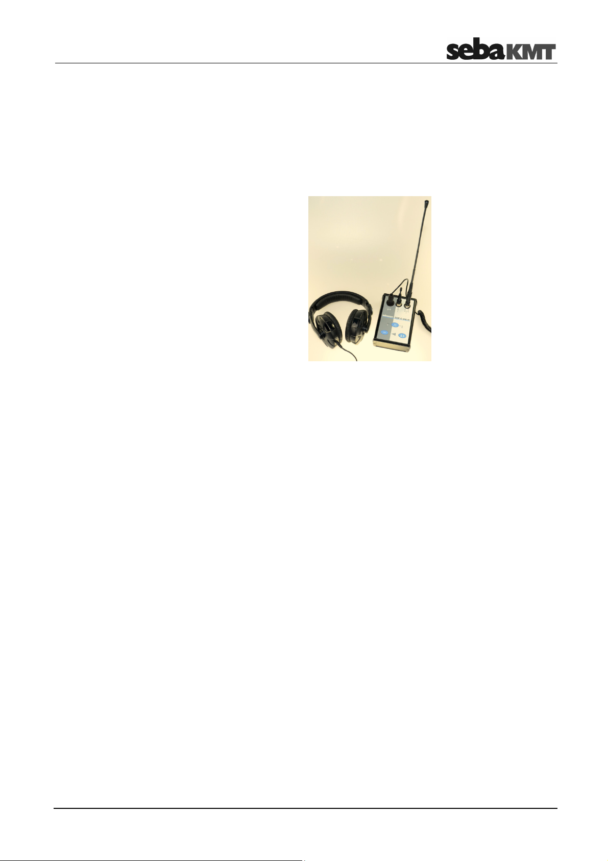
COR C-300-RI
16
3 COR C-300-RI
3.1 Function and design
The COR C-300-RI is a portable device, acting as a radio interface between a PC or
laptop and the sensor devices of the COR C-3 system. With the C-300-RI it is possible
to program/configure the Multisensors (COR MS-3) and receive the analog signal of the
Power-Transmitters (COR PT-3).
The C-300-RI has two external connectors to connect two different antennas - one for
digital communication and one for long range analog communication.
Element
Description
Headset connector
Digital antenna socket
Analog antenna socket
Audio channel switch button
A/B, A mono, B mono
Volume up/down button
3.2 Power supply
The USB connector is used for data transfer and power supply
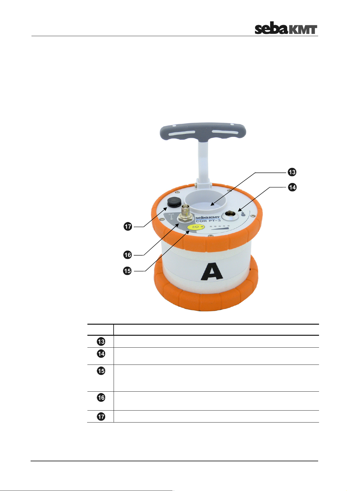
The Power transmitters
17
4 The Power transmitters
4.1 Function and Design
Each Power transmitter has an active amplifier for the microphone signal, a data
memory, a rechargeable Li-Ion battery, a digital radio module and an analogue radio
module with antenna inside.
The sensors have the following external characteristics:
Element
Description
Microphone storage place
Sensor socket
for connecting the microphone / hydrophone
I/O pushbutton
short pressing ...
switches the device on
long pressing ...
Switches the device off
Antenna socket
Antenna socket for connecting the analogue radio antenna
Ventilation/venting membrane

The Power transmitters
18
The Power transmitters have the following lights (LEDs):
Element
Description
LED bar
lit green ...
represents the current battery level
lit red ...
represents the noise level
I/O LED
lit green ...
the transmitter is switched on
flashing ...
the device is charging
not lit ...
the transmitter is switched off
Radio LED
lit red ...
the transmitter is in "Active" mode,
noise measurement in progress,
measurement data is being sent to the Correlator
not lit ...
the transmitter is in "Stand-by" mode,
no measurement in progress,
no radio traffic
Indicator lights

The Power transmitters
19
4.2 Identification number (ID)
Each Power transmitter has its own six-digit identification number (short: ID). Using this
ID the device can be managed and clearly identified in the Correlator, computer and
within the SebaKMT-Cloud.
The ID is deduced from the last six digits of the device's serial number (short: SN). You
find the serial number on the nameplate of the device.
When entering an ID on the Correlator or computer, the preceding zero digits can be
omitted.
4.3 Power supply
The Power transmitters are fitted with internal rechargeable Li-Ion batteries This can
power the device for approximately 12 hours.
In the Start menu of the Correlator two battery icons indicate the current battery status
of the Power transmitters.
On the Power transmitters, the current battery status is indicated by the LED bar
when it is green. If only one of five LEDs is lit, the device should be charged. Otherwise,
it switches itself off automatically.
Red light represents the recorded noise during the measurement and not the battery
status.
The Power transmitters are charged wirelessly in the transport case. The case must be
connected to a power supply. As soon as the Power transmitters are situated at their
storage places in the case, they are recharged inductively.
Charging takes approximately 12 hours. The I/O LED flashes when loading. The
LED bar indicates the progress of charging The I/O LED turns back to permanent
light as soon as the battery is full.
CAUTION
No objects must be put into empty charging stations.
Risk of fire!
The charging stations are for transport and charging of the devices only.
NOTE
Any repairs must be carried out by SebaKMT or an authorized service
partner.
Otherwise, the devices' resistance against water and dirt cannot be
guaranteed.
Do not open the device yourself. If you have problems with the battery,
please contact your SebaKMT service partner.
Battery level
Charging

The Power transmitters
20
4.4 Commissioning
To turn on, briefly press the I/O pushbutton . The I/O LED is lit green when the
device is turned on. To turn the device off, press the button until the LED goes out.
The microphone's storage place is fitted with a magnetic switch. As a result, the
Power transmitter "knows" whether the microphone is currently in use or not.
As long as the microphone rests in its storage place, the Power transmitter remains in
"Stand-by" mode. The internal analogue radio module stays off as no measuring data
needs to be transferred to the Correlator. This saves battery power.
As soon as the microphone is taken from the storage place, the Power transmitter
switches from "Stand-by" to "Active" mode. The radio module is activated. From now on,
the recorded data are directly sent to the Correlator. The row of LEDs switches from
green to red and represents the recorded noise level.
4.5 Installation
The sensors should be installed directly on the pipe but, however, you can also attach
them to valve rods or hydrants, for example, or any other position along the pipeline that
is easily accessible.
There must be the best possible contact between the sensor foot or the mounted
adapter (see below) and the pipe. If need be, clean the contact point thoroughly
(preferably with a wire brush).
In some situations it might be helpful to use one of the supplied magnetic angle
adapters.
Switching ON/OFF
Stand-by
Table of contents
Other sebaKMT Measuring Instrument manuals


