sebaKMT UDM-300 User manual

Edition: 01 (03/2015) - EN
Art.No.: 84568
Mess- und Ortungstechnik
Measuring and Locating Technologies
Elektrizitätsnetze
Power Networks
Kommunikationsnetze
Communication Networks
Rohrleitungsnetze
Water Networks
Abwassernetze
Sewer Systems
Leitungsortung
Line Locating
User Manual
Ultrasonic Flow Measurement Device
UDM-300


Consultation with SebaKMT
The present system manual has been designed as an operating guide and for reference. It is meant to
answer your questions and solve your problems in as fast and easy a way as possible. Please start with
referring to this manual should any trouble occur.
In doing so, make use of the table of contents and read the relevant paragraph with great attention.
Furthermore, check all terminals and connections of the instruments involved.
Should any question remain unanswered, please contact:
Seba Dynatronic
Mess- und Ortungstechnik GmbH
Hagenuk KMT
Kabelmesstechnik GmbH
Dr.-Herbert-Iann-Str. 6
D - 96148 Baunach
Phone: +49 / 9544 / 68 – 0
Fax: +49 / 9544 / 22 73
Röderaue 41
D - 01471 Radeburg / Dresden
Phone: +49 / 35208 / 84 – 0
Fax: +49 / 35208 / 84 249
E-Mail: sales@SebaKMT.com
http://www.SebaKMT.com
SebaKMT
All rights reserved. No part of this handbook may be copied by photographic or other means unless SebaKMT have before-hand declared
their consent in writing. The content of this handbook is subject to change without notice. SebaKMT cannot be made liable for technical or
printing errors or shortcomings of this handbook. SebaKMT also disclaim all responsibility for damage resulting directly or indirectly from
the delivery, supply, or use of this matter.

Terms of Warranty
SebaKMT accept responsibility for a claim under warranty brought forward by a customer for a product sold by
SebaKMT under the terms stated below.
SebaKMT warrant that at the time of delivery SebaKMT products are free from manufacturing or material
defects which might considerably reduce their value or usability. This warranty does not apply to faults in the
software supplied. During the period of warranty, SebaKMT agree to repair faulty parts or replace them with
new parts or parts as new (with the same usability and life as new parts) according to their choice.
This warranty does not cover wear parts, lamps, fuses, batteries and accumulators.
SebaKMT reject all further claims under warranty, in particular those from consequential damage. Each
component and product replaced in accordance with this warranty becomes the property of SebaKMT.
All warranty claims versus SebaKMT are hereby limited to a period of 12 months from the date of delivery.
Each component supplied by SebaKMT within the context of warranty will also be covered by this warranty for
the remaining period of time but for 90 days at least.
Each measure to remedy a claim under warranty shall exclusively be carried out by SebaKMT or an authorized
service station.
This warranty does not apply to any fault or damage caused by exposing a product to conditions not in
accordance with this specification, by storing, transporting, or using it improperly, or having it serviced or
installed by a workshop not authorized by SebaKMT. All responsibility is disclaimed for damage due to wear,
will of God, or connection to foreign components.
For damage resulting from a violation of their duty to repair or re-supply items, SebaKMT can be made liable
only in case of severe negligence or intention. Any liability for slight negligence is disclaimed.
Since some states do not allow the exclusion or limitation of an implied warranty or of consequential damage,
the limitations of liability described above perhaps may not apply to you.

Имеется возможность выбора языка информации, отображаемой на экране преобразователя
(смотри подраздел 8.5).
De transmitter kan worden gebruikt in de taal van uw keuze (zie paragraaf 8.5).
El caudalímetro puede ser manejado en el idioma de su elección (ver sección 8.5).
Il est possible de sélectionner la langue utilisée par le transmetteur à l'écran (voir section 8.5).
The transmitter can be operated in the language of your choice (see section 8.5).
Die Sprache, in der die Anzeigen auf dem Messumformer erscheinen, kann eingestellt werden (siehe Ab-
schnitt 8.5).


Table of Contents
1INTRODUCTION 9
1.1
Regarding this User Manual 9
1.2
Safety Instructions 9
1.3
Warranty 9
2HANDLING 10
2.1
First Inspection 10
2.2
General Precautions 10
2.3
Cleaning 10
2.4
Storage 10
3GENERAL PRINCIPLES 11
3.1
Measurement System 11
3.2
Measurement Principle 11
3.2.1
Terms 11
3.2.2
Measurement of the Flow Velocity 12
3.3
MeasurementArrangements 14
3.3.1
Terms and Definitions 14
3.3.2
Examples 15
4DESCRIPTION OF THE TRANSMITTER 16
4.1
Construction 16
4.2
State Indication 17
4.3
Keyboard 17
5SELECTION OF THE MEASURING POINT 18
5.1
AcousticPenetration 18
5.2
Undisturbed Flow Profile 20
5.3
Selection of the Measurement Arrangement Taking onto Account the Measuring
Range and the
Measuring Conditions 22
5.4
Selection of the Sound Beam Plane Near an Elbow 23
6INSTALLATION OF UDM 300 24
6.1
Location 24
6.2
Connection of the Transducers 24
6.3
Power Supply 24
6.3.1
Power Supply with the Battery 24
6.3.2
Power Supply with the Power Supply Unit 24
6.4
Connection of the Outputs 25
Output adapter (Option) 26
6.5
Connection of the Serial Interface RS232 26
7INSTALLATION OF THE TRANSDUCERS 27
7.1
Preparation of the Pipe 27
7.2
Orientation of the Transducers and Transducer Distance 27
7.3
Mounting of the Transducers with Transducer Clamping Fixture and Ladder Chains 27
7.4
Mounting of the Transducers with Transducer Shoe and Ball Chains 28
8START-UP OF THE TRANSMITTER 29
8.1
Switching on 29
8.2
Initialization 29
8.3
Display 29
8.3.1
Main Menu 29
8.3.2
Program Branches 30
8.3.3
Navigation 31
8.4
HotCodes 31
8.5
LanguageSelection 32
9BASIC MEASUREMENT 33
9.1
Input of the Pipe Parameters 33
9.1.1
Outer Pipe Diameter/Pipe Circumference 33
9.1.2
Pipe Wall Thickness 33
9.1.3
Pipe Material 33

9.1.4
Pipe Lining 34
9.1.5
Pipe Roughness 34
9.2
Input of the Medium Parameters 34
9.2.1
Medium Temperature 34
9.3
TransducerSelection 34
9.4
Defining the Measuring Point Number 35
9.5
Defining the Number of Sound Paths 35
9.6
TransducerDistance 35
9.6.1
Fine Adjustment of the Transducer Distance 35
9.6.2
Consistency Check 36
9.6.3
Value of the Sound Speed 36
9.7
Start of the Measurement 36
9.8
Detection of the Flow Direction 37
9.9
Interruption of the Measurement 37
10 DISPLAYING THE MEASURED VALUES 38
10.1
Selection of the Physical Quantity and of the Unit of Measurement 38
10.2
Adjustment of the Display 38
10.3
Status Line 39
10.4
TransducerDistance 40
11 ADVANCED MEASURING FUNCTIONS 41
11.1
Command Execution during Measurement 41
11.2
Damping Factor 41
11.3
Totalizers 41
11.4
Upper Limit of the Flow Velocity 42
11.5
Cut-off Flow 43
11.6
Uncorrected Flow Velocity 43
11.7
Program Code 44
11.7.1
Defining a Program Code 44
11.7.2
Intervention in the Measurement 44
11.7.3
Deactivation of the Program Code 44
12 DATA LOGGER AND TRANSMISSION OF DATA 45
12.1
Data Logger 45
12.1.1
Activation/Deactivation of the Data Logger 45
12.1.2
Setting the Storage Rate 45
12.1.3
Settings of the Data Logger 45
12.1.4
Measurement with Activated Data Logger 47
12.1.5
Deleting the Measured Values 47
12.1.6
Available Data Logger Memory 47
12.2
Transmission of Data 48
12.2.1
Online Transmission of Data 48
12.2.3
Formatting of the Measurement Data 48
12.2.4
Transmission Parameters 49
12.2.5
Online Transmission of Data to a Terminal Program 49
12.2.6
Offline Transmission of Data to a Terminal Program 50
12.2.7
Offline Transmission of Data with the Program FluxData 50
12.2.8
Structure of the Data 52
13 SETTINGS 53
13.1
Time and Date 53
13.1.1
Time 53
13.1.2
Date 53
13.2
Dialogs and Menus 53
13.2.1
Pipe Circumference 53
13.2.2
Measuring Point Number 54
13.2.3
Transducer Distance 54
13.2.4
Error Value Delay 54
13.2.5
Alarm State Indication 54
13.2.6
Units of Measurement 54
13.2.7
Setting for the Medium Pressure 55
13.3
Measurement Settings 55
13.4
Setting the Contrast 56
13.5
InstrumentInformation 56

14 SUPERUSER MODE 57
14.1
Activation/Deactivation 57
14.2
Defining the Flow Parameters 57
14.2.1
Profile Bounds 57
14.2.2
Correction of the Flow Velocity 58
14.3
Limit of the Signal Amplification 59
14.4
Upper Limit of the Sound Speed 59
14.5
Detection of Long Measurement Failures 59
14.6
Number of Decimal Places of the Totalizers 60
14.7
Manual Reset of the Totalizers 60
14.8
Display of the Sum of the Totalizers 61
14.9
Display of the Last Valid Measured Value 61
14.10
Display During the Measurement 61
15 OUTPUTS 62
15.1
Installation of an Output 62
15.1.1
Output Range 63
15.1.2
Error Output 63
15.1.3
Function Test 65
15.2
Error Value Delay 65
15.3
Activation of an Analog Output 65
15.3.1
Measuring Range of the Analog Output 66
15.3.2
Function Test 66
15.4
Activation of a Binary Output as a Pulse Output 66
15.5
Activation of a Binary Output as an Alarm Output 67
15.5.1
Alarm Properties 67
15.5.2
Setting the Limits 68
15.5.3
Defining the Hysteresis 69
15.6
Behavior of the Alarm Output 69
15.6.1
Apparent Switching Delay 69
15.6.2
Reset and Initialization of the Alarms 69
15.6.3
Alarm Outputs During Transducer Positioning 69
15.6.4
Alarm Output During the Measurement 70
15.6.5
Indication of the Alarm State 70
15.6.6
Deactivation of the Output 71
16 TROUBLESHOOTING 72
16.2
Selection of the Measuring Point 73
16.3
Maximum Acoustic Contact 73
16.4
Application Specific Problems 73
16.5
Large Deviations of the Measured Values 73
16.6
Problems with the Totalizers 74
16.7
Data Transmission 74
17 MENU STRUCTURE 75
18 TECHNICAL DATA 83
18.1
Flow Transmitter 83
18.2
Transducers 84
19 UNITS OF MEASUREMENT 85
20 REFERENCE 90
20.1
Sound Speed of Selected Pipe and Lining Materials at 20 °C (68 °F) 90
20.2
Typiacal Roughnesses of Pipes 91
20.3
Properties of Water at 1 bar and at Saturation Pressure 92


9
1 Introduction
1.1
Regarding this User Manual
This user manual has been written for the personnel operating the ultrasonic flowmeter UDM 300. It contains important in-
formation about the measuring instrument, how to handle it correctly, and how to avoid damages.
Read the safety instructions carefully. Make sure you have read and understood this user manual before using the mea-
suring instrument.
All reasonable effort has been made to ensure the correctness of the content of this user manual. However, If you find any
erroneous information, please inform us. We will be grateful for any suggestions and comments regarding the concept and
your experience working with the measuring instrument.
This will ensure that we can further develop our products for the benefit of our customers and in the interest of technologi-
cal progress. If you have any suggestions about improving the documentation and particularly this user manual, please let
us know so that we can consider your comments for future reprints.
The contents of this user manual are subject to changes without prior notice. All rights reserved. No part of this user man-
ual may be reproduced in any form without SEBAKMT's written permission.
1.2
Safety Instructions
The user manual contains instructions that are marked as follows:
Observe these safety instructions!
1.3
Warranty
The UDM 300 measuring instrument is guaranteed for the term and to the conditions specified in the sales contract provid-
ed the equipment has been used for the purpose for which it has been designed and operated according to the instruc-
tions given in this User Manual. Misuse of the UDM 300 will immediately revoke any warranty given or implied.
This includes:
•replacement of a component of UDM 300 with a component that was not approved by SEBAKMT
•unsuitable or insufficient maintenance
•repair of UDM 300 by unauthorized personnel
SEBAKMT assumes no responsibility for injury to the customer or third persons proximately caused by the material owing
to
defects in the product which were not predictable or for any indirect damages.
The UDM 300 is a very reliable instrument. It is manufactured under strict quality control using modern production
techniques. If installed as recommended in an appropriate location, used cautiously and taken care of conscientiously,
no troubles should appear.
In case of a problem which cannot be solved with the help of this user manual (see chapter 16), contact our sales office
giving a precise description of the problem. Specify the type, serial number and firmware version of the measuring instru-
ment.
Attention!
This text contains important instructions which should be observed to avoid damage or destruction of
the measuring instrument. Proceed with special caution!
Note! This text contains important information about the use of the measuring instrument.

10
2 Handling
2.1
First Inspection
The measuring instrument has already been tested thoroughly at the factory. At delivery, proceed to a visual control to
make sure that no damage has occurred during transportation.
Check that the specifications of the measuring instrument delivered correspond to the specifications given on the pur-
chase order.
The type and the serial number of the transmitter are shown on the nameplate. The transducer type is printed on the trans-
ducers.
2.2
General Precautions
The UDM 300 is a precision measuring instrument and has to be handled with care. To obtain good measurement results
and not damage the measuring instrument, it is important that great attention is paid to the instructions given in this user
man- ual, particularly to the following points:
•Protect the transmitter from shocks.
•Keep the transducers clean. Manipulate the transducer cables with caution. Avoid excessive cable bend.
•Make sure to work under correct ambient and operating temperatures. The ambient temperature has to be within the op-
erating temperature range of the transmitter and the transducers (see annex B).
•Observe the degree of protection (see annex B).
2.3
Cleaning
•Clean the transmitter with a soft cloth. Do not use detergents.
•Remove traces of the coupling compound from the transducers with a soft paper towel.
2.4
Storage
•Wipe the transducers clean of traces of the coupling compound.
•After the measurement, always put the transmitter and its accessories into the corresponding compartments of the trans-
port case.
•Avoid excessive cable bends, especially when closing the cover of the transport case.
•Observe the notes on the storage of the battery (see Storage of the battery in section 6.3.1).

11
3 General Principles
For the ultrasonic measurement of the flow rate, the flow velocity of the medium flowing in a pipe is determined. Further
physical quantities (e.g., volumetric flow rate, mass flow rate) are derived from the flow velocity and from additional physi-
cal quantities, if necessary.
3.1
Measurement System
The measurement system consists of a transmitter, the ultrasonic transducers with the transducer cables and the pipe on
which the measurement is conducted.
The ultrasonic transducers are mounted on the outside of the pipe. Ultrasonic signals are sent through the medium and re-
ceived by the transducers. The transmitter controls the measuring cycle, eliminates the disturbance signals and analyzes
the useful signals. The measured values can be displayed, used for calculations and transmitted.
transmitter
Fig. 3.1: Example of a measurement setup
3.2
Measurement Principle
The flow velocity of the medium is measured using the transit time difference correlation principle (see section 3.2.2).
3.2.1
Terms
Flow profile
Distribution of the flow velocities over the cross-sectional pipe area. For an optimal measurement, the flow profile has to
be fully developed and axisymmetrical. The shape of the flow profile depends on whether the flow is laminar or turbulent
and is influenced by the conditions in the supply line of the measuring point (see chapter 5).
Reynolds number Re
Coefficient describing the turbulence behavior of a medium in the pipe. The Reynolds number Re is calculated from the
flow velocity, the kinematic viscosity of the medium and the inner pipe diameter.
If the Reynolds number exceeds a critical value (usually approx. 2 300, if the medium flows in a pipe), a transition from a
laminar flow to a turbulent flow takes place.
Laminar flow
A flow without any turbulence. There is no disruption between the parallel flowing layers of the medium.
Turbulent flow
A flow in which turbulence (swirling of the medium) occurs. In technical applications, the flow in the pipe is mostly turbu-
lent.
Transition range
The flow is partly laminar and partly turbulent.
Transit time difference ∆t
Difference of the transit times of the signals in and against the flow direction. The flow velocity of the medium in the pipe is
determined from the transit time difference (see Fig. 3.2, Fig. 3.3 and Fig. 3.4).
Sound speed c
Speed of the propagating sound. The sound speed depends on the mechanical properties of the medium or the pipe ma-
terial. In pipe materials and other solid materials, a distinction is made between the longitudinal and transversal sound
speed. For the sound speed of some media and materials see annex D.1.
transducers
pipe

12
V
Re a
Flow velocity v
average value of the flow velocities over the cross-sectional pipe area.
Acoustic calibration factor ka
cα
------------
sinα
The acoustic calibration factor ka is a parameter of the transducer which results from the sound speed c within the trans-
ducer and the angle of incidence (see Fig. 3.2). According to Snell's law of refraction, the angle of propagation in the ad-
joining medium or pipe material is:
cα
------------
cβ
------------
cγ
-----------
ka = sinα = sinβ = sinγ ·
Volumetric Flow Rate V
·
V = v · A
The volume of the medium that passes through the pipe per unit time. The volumetric flow rate is calculated from the prod-
uct of the flow velocity v and the cross-sectional pipe area A.
Fluid mechanics correction factor kRe
With the fluid mechanics correction factor kRe, the measured value of the flow velocity in the area of the sound beam is
converted into the value of the flow velocity across the whole cross-sectional pipe area. In case of a fully developed flow
profile, the fluid mechanics correction factor only depends on the Reynolds number and the roughness of the inner pipe
wall. The fluid mechanics correction factor is recalculated by the transmitter for each new measurement.
Mass flow rate m
·
·
m
· = V · ρ
The mass of the medium that passes through the pipe per unit time. The mass flow rate is calculated from the product of
the volumetric flow rate · and the density ρ.
3.2.2
Measurement of the Flow Velocity
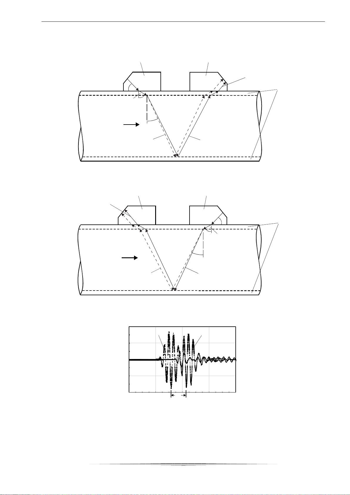
The signals are emitted and received by two transducers alternatively in and against the flow direction. If the medium
moves, the signals propagating in the medium are displaced with the flow. This displacement causes a reduction in dis-
tance for the signal in the flow direction and an increase in distance for the signal against the flow direction in the wedge of
the receiving transducer (see Fig. 3.2 and Fig. 3.3). This causes a change in the transit times. The transit time of the signal
in the flow direction is shorter than the transit time against the flow direction. This transit time difference is proportional to
the average flow velocity.
The flow velocity of the medium is calculated as follows:
∆t
v = k · k · ------------
2 ⋅ t
fl
with
v – flow velocity of the medium
kRe –fluid mechanics correction factor
ka –acoustic calibration factor
∆t – transit time difference
tfl –transit time in the medium
ka =
13
transducer (emitter) transducer (receiver)
c
α
c
α
α
c
β
β
γ
reduction in distance
in the transducer
pipe wall
flow direction cγ
of the medium
sound path without flow sound path with flow
Fig. 3.2: Sound path of the signal in the flow direction
transducer (receiver) transducer (emitter)
increase in distance
in the transducer
c
α
cα
α
cβ
β
pipe wall
γ
flow direction cγ
of the medium
sound path without flow sound path with flow
Fig. 3.3: Sound path of the signal against the flow direction
Fig. 3.4: Transit time difference ∆t
signal in th
flow directio
e
n
nal
against
flow direction
sig
the
∆t

14
transducer distance
3.3
Measurement Arrangements
3.3.1
Terms and Definitions
Diagonal arrangement
The transducers are mounted on the opposite sides of the pipe (see Fig. 3.5).
Reflection arrangement
The transducers are mounted on the same side of the pipe (see Fig. 3.6).
Fig. 3.5: Diagonal arrangement Fig. 3.6: Reflection arrangement
Sound path
The distance covered by the ultrasonic signal after crossing the pipe once. The number of the sound paths is:
•odd if the measurement is conducted in the diagonal arrangement (see Fig. 3.5)
•even if the measurement is conducted in the reflection arrangement (see Fig. 3.6).
Transducer distance
Distance between the transducers. It is measured between the inner edges of the transducers.
reflection arrangement
diagonal arrangement
(positive transducer distance)
diagonal arrangement
(negative transducer distance)
transducer distance
transducer distance

16
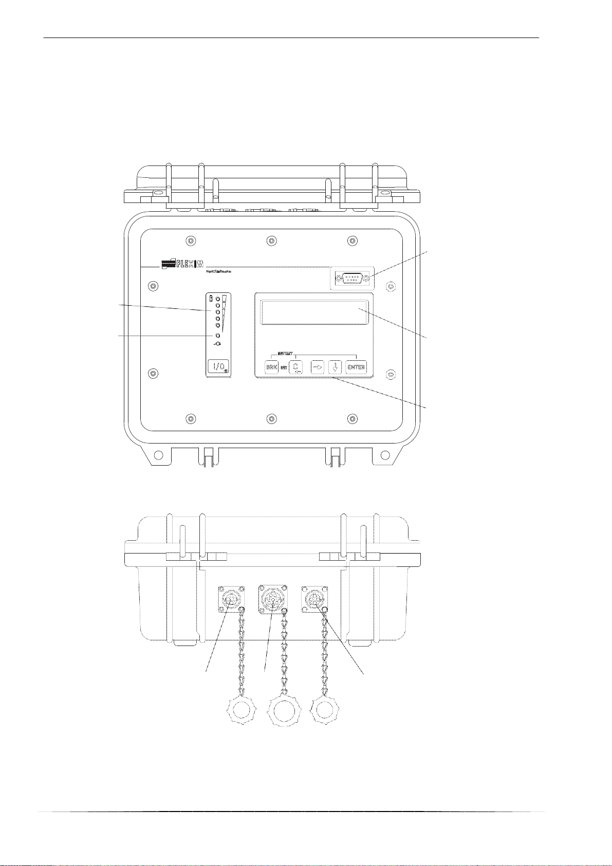
4 Description of the Transmitter
4.1
Construction
The cover has to be opened to access the command panel.
RS232 interface
state indicator
"charge state"
state indicator
"power supply"
2 x 16-digit LCD display,
backlift
keyboard
Fig. 4.1: Command panel of UDM 300
Fig. 4.2: Connections of UDM 300
output
transducer
power supply unit/
battery charging unit

17
4.2
State Indication
The state indicators light only when the transmitter is switched on and the backlight is activated.
Tab. 4.1: State indicator "power supply"
LED flashes green
transmitter is connected to the power supply; battery is charging
LED light green
transmitter is connected to the power supply; battery is charged
LED flashes red
battery is almost empty
Tab. 4.2: State indicator "charge state" (red LEDs)
4.3
Keyboard
The keyboard consists of 5 keys.
Tab. 4.3: General functions
I/O
switching the transmitter on/off
switching the backlight on/off
To switch off the transmitter press the I/O key for 3 seconds.
ENTER
confirmation of selection or entered value
BRK + C
INIT: When switching on the transmitter press these two keys simultaneously to execute the
initialization (see section 8.2).
BRK + C + ENTER
RESET: Press these three keys simultaneously to correct a malfunction. The reset has the
same effect as restarting the transmitter. Stored data are not affected.
BRK
interruption of the measurement and selection of the main menu
Be careful not to stop a current measurement by inadvertently pressing key BRK!
Tab. 4.4: Navigation
scroll to the right or up through a scroll list
scroll to the left or down through a scroll list
Tab. 4.5: Input of digits
move the cursor to the right
scroll through the digits above the cursor
C
Move the cursor to the left. If the cursor is on the left margin:
•an already edited value will be reset to the value which was stored previously
•an unedited value will be deleted.
If the entered value is not valid, an error message will be displayed. Press ENTER and enter a
correct value.
Tab. 4.6: Input of text
move the cursor to the right
scroll through the characters above the cursor
C
reset all characters to the last stored entry
LEDs light number of LED lights displays the charge state of the battery

18
5 Selection of the Measuring Point
The correct selection of the measuring point is crucial for achieving reliable measurement results and a high measurement
accuracy.
A measurement on a pipe is possible if
•the ultrasound propagates with a sufficiently high amplitude (see section 5.1)
•the flow profile is fully developed (see section 5.2)
The correct selection of the measuring point and thus, the correct transducer positioning guarantees that the sound signal
will be received under optimum conditions and evaluated correctly.
Due to the variety of applications and the different factors that influence the measurement, there is no standard solution for
the transducer positioning. The correct position of the transducers is influenced by the following factors:
•diameter, material, lining, wall thickness and shape of the pipe
•medium
•gas bubbles in the medium
Avoid measuring points in the vicinity of deformations and defects of the pipe and in the vicinity of welds.
Avoid locations with deposit formation in the pipe.
The ambient temperature at the measuring point has to be within the operating temperature range of the transducers (see
annex B).
Select the location of the transmitter within cable reach of the measuring point.
The ambient temperature at the location has to be within the operating temperature range of the transmitter (see
annex B).
5.1
Acoustic Penetration
The pipe has to be acoustically penetrable at the measuring point. The acoustic penetration is reached when pipe and me-
dium do not attenuate the sound signal so strongly that it is completely absorbed before reaching the second transducer.
The attenuation in the pipe and in the medium depends on:
•kinematic viscosity of the medium
•proportion of gas bubbles and solids in the medium
•deposits on the inner pipe wall
•pipe material
The following requirements have to be met at the measuring point:
•the pipe is always filled completely
•no material deposits in the pipe
•no bubbles accumulate
Observe the notes in the following table.
Note!
Even bubble-free media can form gas bubbles when the medium expands, e.g., before pumps and
after great cross-section extensions.
Table of contents
Other sebaKMT Measuring Instrument manuals


