Secabo C30III User manual

OPERATING INSTRUCTIONS
for vinyl cutters
Secabo C30III, C60III and C120III
Congratulations on purchasing a Secabo vinyl cutter!
Please read these operating instructions thoroughly to ensure that you can start
production with your vinyl cutter without problems.
Reproduction of these operating instructions in any form requires written approval of
Secabo GmbH. e reserve all rights to change technical data and product features
without prior notice. Not liable for printing errors.
Secabo GmbH does not assume any liability for direct or indirect damage or injury
resulting from use of this product.
Version 1.7 (09.06.2010)

Table of Contents
Table of ContentsTable of Contents
Table of Contents
1
11
1
Safety Precautions
Safety PrecautionsSafety Precautions
Safety Precautions ................................
................................................................
................................................................
................................................................
...................................................
......................................
................... 2
22
2
2
22
2
Items Included
Items IncludedItems Included
Items Included ................................
................................................................
................................................................
................................................................
........................................................
................................................
........................ 3
33
3
3
33
3
Layout of Stand
Layout of StandLayout of Stand
Layout of Stand-
--
-Up
UpUp
Up-
--
-Base
BaseBase
Base................................
................................................................
................................................................
................................................................
..........................................
....................
.......... 4
44
4
4
44
4
Unit Description
Unit DescriptionUnit Description
Unit Description ................................
................................................................
................................................................
................................................................
......................................................
............................................
...................... 5
55
5
4.1
Unit Parts and Their Function.................................................................5
4.2
Side Views ...........................................................................................5
4.3
Control Panel.......................................................................................6
5
55
5
Starting Up Appliance and Software
Starting Up Appliance and SoftwareStarting Up Appliance and Software
Starting Up Appliance and Software ................................
................................................................
..........................................................
....................................................
.......................... 7
77
7
5.1
Starting Up Appliance...........................................................................7
5.2
Start-up of the device and software ........................................................7
5.3
Installation SignCut Productivity Pro .......................................................7
5.3.1
Installation of the device driver.........................................................8
5.3.2
Installation of the Secabo cutting plotter in SignCut Productivity Pro.....8
5.4
Installation of the Illustrator Export Plugins for CS2, CS3 and CS4............8
5.4.1
Import of an .eps file into SignCut Productivity Pro .............................9
5.5
Installing and Adjusting the Blade ..........................................................9
5.6
Inserting the Blade Holder...................................................................10
5.7
Inserting cutting vinyl ..........................................................................10
5.8
Cutting Test .......................................................................................11
6
66
6
Settings and Operation
Settings and OperationSettings and Operation
Settings and Operation ................................
................................................................
................................................................
................................................................
..........................................
....................
.......... 12
1212
12
6.1
Online/Offline ...................................................................................12
6.2
Moving the Cutting Head....................................................................12
6.3
Setting the Zero Point .........................................................................12
6.4
Changing ..........................................................................................13
6.5
Repeat Function .................................................................................13
6.6
Other Settings....................................................................................14
6.7
Limit Switches.....................................................................................14
7
77
7
Drag knifes
Drag knifesDrag knifes
Drag knifes ................................
................................................................
................................................................
................................................................
...........................................................
......................................................
........................... 15
1515
15
8
88
8
Technical Data
Technical DataTechnical Data
Technical Data................................
................................................................
................................................................
................................................................
......................................................
............................................
...................... 16
1616
16
9
99
9
Troubleshooting
TroubleshootingTroubleshooting
Troubleshooting ................................
................................................................
................................................................
................................................................
....................................................
........................................
.................... 17
1717
17

2
1Safety Precautions
Please read these instructions and safety precautions carefully before using your
vinyl cutter for the first time!
•Do not place any magnetic objects in the vicinity of the cutting head;
otherwise uniform contact pressure is not ensured.
•Do not remove the connection cable to the computer while plotting is in
progress.
•Relieve the pressure on the pressure rollers when not in use by moving the
pressure lever up.
•Do not reach into the unit with your hands when the power is connected.
•Never open the housing or attempt to modify the unit yourself.
•Ensure that liquids and metal objects do not get into the inside of the plotter.
•Ensure that the wall socket used is grounded and protected with a ground
fault switch.
•Ensure that the connected voltage (220V) does not deviate by more than
±10%. Otherwise install a voltage stabilizer.
•Disconnect the power cord when the unit is not used for a longer period of
time.
•Never reach into the unit in the vicinity of the blade holder during the cutting
operation!
•Discontinue any printing jobs in progress before readjusting the blade holder!
•Always ensure that the vinyl cutter is out of reach of children during operation
and never leave the unit or individual parts of it switched on without
supervision.
•Do not touch the tip of the sliding blade to avoid injury.
•Always place the unit on a stable base to prevent it from falling down.
•Do not operate the unit during thunderstorms; it can be damaged or
destroyed by lightning.

3
2Items Included
Before starting work, please check whether the following items are all present:
Item Quantit
Power cable 1
Serial connection
cable 1
USB connection
cable 1
Bladeholder 1
Penholder 1
45° drag knife 3
Pens 2
Secabo FlexiStarter 1
Stand-up-base
(not with C30III)
1

4
3Layout of Stand-Up-Base
Tools required: Phillips screwdriver, 13 mm wrench,
The stand-up base for your Secabo vinyl cutter can be assembled simply using the
parts supplied as shown in the exploded drawing above.

5
4Unit Description
4.1 Unit Parts and T eir Function
4.2 Side Views
USB-port, serial port
Power supply, fuse, switch
Blade Holder
Grid rollers
Control panel
Cutting head
Base

6
4.3 Control Panel
a) Online-/Offline button
b) Test button (blade test)
c) LCD display
d) Arrow keys for control of cutting head and for pulling in foil
e) Zero point button
f) Pause button (to interrupt plotting operation)
g) Repeat button for repeating a job
h) Menu button for appliance settings
d
c
b
a
h
g
f
e

7
5Starting Up Appliance and Software
5.1 Starting Up Appliance
Ensure that sufficient space is present for the foil transport in front of and in back of
the unit. The vinyl cutter should be operated only in clean and dry surroundings.
•Connect the plotter to a 220 V wall socket with the power cable provided.
•Then switch the plotter on. Caution! After switching on, the cutting head
initially moves to the right.
5.2 Start-up of t e device and software
Attention!
Attention! Attention!
Attention! Please consider that smooth installation and full configuration requires
Please consider that smooth installation and full configuration requires Please consider that smooth installation and full configuration requires
Please consider that smooth installation and full configuration requires
the prior installation of SignCut Productivity Pro.
the prior installation of SignCut Productivity Pro. the prior installation of SignCut Productivity Pro.
the prior installation of SignCut Productivity Pro.
5.3 Installation SignCut Productivity Pro
Your Secabo cutting plotter is delivered along with the cutting plotter software
SignCut Productivity Pro with Bundle Registration Code. Please sign in on
http://www.signcutpro.com/ under „Register Bundle“ to install SignCut Productivity
Pro. After entry of the Bundle Registration Code the licence number is created and
displayed subsequently. Please state the licence number to activate the licence;
SignCut Productivity Pro is then subsequently active for 12 months. Directly after
licence activation you can also set the device beforehand, but it can only be
controlled after the device driver has been installed. Basic requirement for the
production with Signcut is common graphics software like for example Adobe
Illustrator or Corel Draw. A simple creation of vector graphics is also possible with
the Open Source Software Inkscape.

8
5.3.1 Installation of t e device driver
•Insert the Secabo CIII Driver CD into your CD drive.
•Select the driver necessary for your Mac OSX Version (Intel or power PC) in
the folder Mac OSX/Drivers.
•Activate the .dmg file by clicking on it, and click on the FTDIUSBSerialDriver
file several times.
•Follow the installation steps by entering your user password.
•You are asked to restart your computer, subsequently the device driver is fully
installed.
5.3.2 Installation of t e Secabo cutting plotter in SignCut Productivity Pro
•Open SignCut Productivity Pro, and select the button „Plotter“.
•Select the manufacturer, device type, and the device like the illustrated notice
/dev/cu.usbserial-ftE2MSR0 and click on OK.
5.4 Installation of t e Illustrator Export Plugins for CS2, CS3 and CS4
•Insert the included Secabo CIII Driver CD into your CD- drive.
•Select the file Signcut.aip in the folder MacOSX/Illustrator Export Plugin .
•Copy it into Adobe Illustrator CS3/Additional modules/Tools for example
Adobe Illustrator CS3 .
•Created vector graphics can then be exported directly to SignCut with this
command.

9
•Subsequently the Plugin is active under the menu file/Send to Signcut (see
illustration below).
5.4.1 Import of an .eps file into SignCut Productivity Pro
•Using the menu command Open File you load a vector graphic in .eps
format into SignCut
5.5 Installing and Adjusting t e Blade
•Take one of the cutting blades supplied and place it in the blade holder so
that the sharp side extends at the front. The blade is held by a magnet in the
blade holder.
•Adjust the cutting depths by turning the front cap.
•The depth is initially set correctly when you can carefully move your fingertip
across the blade and feel only a light scratching. Since the depth adjustment
for the blade depends on the material, it may be necessary to change it later
(as a rule 0.05 mm to 0.1 mm).

10
•Press the pin on the rear of the blade holder to remove and replace the blade
at any time. Caution – Injury hazard!
The various material thicknesses require different blade settings or even special
blades; it may therefore be necessary to repeat the adjustment described above.
5.6 Inserting t e Blade Holder
•First turn the clamping screw for the blade holder on the cutting head until it
is open wide enough.
•Then insert the blade holder from the top and press down against the stop in
the hole on the right side and retighten the clamping screw
5.7 Inserting cutting vinyl
•Always insert the material to be printed into the unit from the rear.
•Pull the foil up to the cutting bar in order to correctly set the zero point.
Details on setting the zero point are given under Point 6.3 in these
instructions.
•If you use a roll of foil instead of foil sheets, the foil can be rolled off cleanly
with the aid of the roll holder supplied.
•hen inserting, ensure that the foil is inserted straight to prevent it from
distorting during transport. hen the foil is inserted at an angle of only a few
millimeters, this can lead to the foil running highly off center during long
plotting jobs.
Blade holder
Knurled screw

11
•You can insert the foil into the plotter at any desired point as long as the
pressure rollers are located in the areas of the yellow arrows on the cross-
member.
•Fixieren Sie die beiden Anpressrollen durch Umklappen der Spannhebel an
den Außenkanten der Folie (ca. 2cm eingerückt), damit die Folie gerade
transportiert wird und ein maximaler Schneidebereich gewährleistet ist.
5.8 Cutting Test
•To perform the cutting test in the offline mode, press the Test button; the
plotter then cuts a rectangle in the inserted foil at the currently stored zero
point.
•You can check the adjustment of the blade holder as well as the contact
pressure with this cutting test. The material inserted should be cut cleanly and
straight during the cutting test; the backing material should not be damaged.
•If the backing material has been cut through, either the contact pressure is set
too high or the blade or blade holder is adjusted incorrectly. Change these
adjustments and perform the cutting test again.
•Also readjust if the foil was cut imprecisely or to an insufficient depth.

12
6Settings and Operation
6.1 Online/Offline
After switching on the unit a reset is performed and the unit switches to the online
mode. You can switch back and forth between the online and offline mode by
pressing the Online button on the control panel. During the cutting operation, the
vinyl cutter must generally be in the online mode, to change the configuration
settings, the unit must be offline.
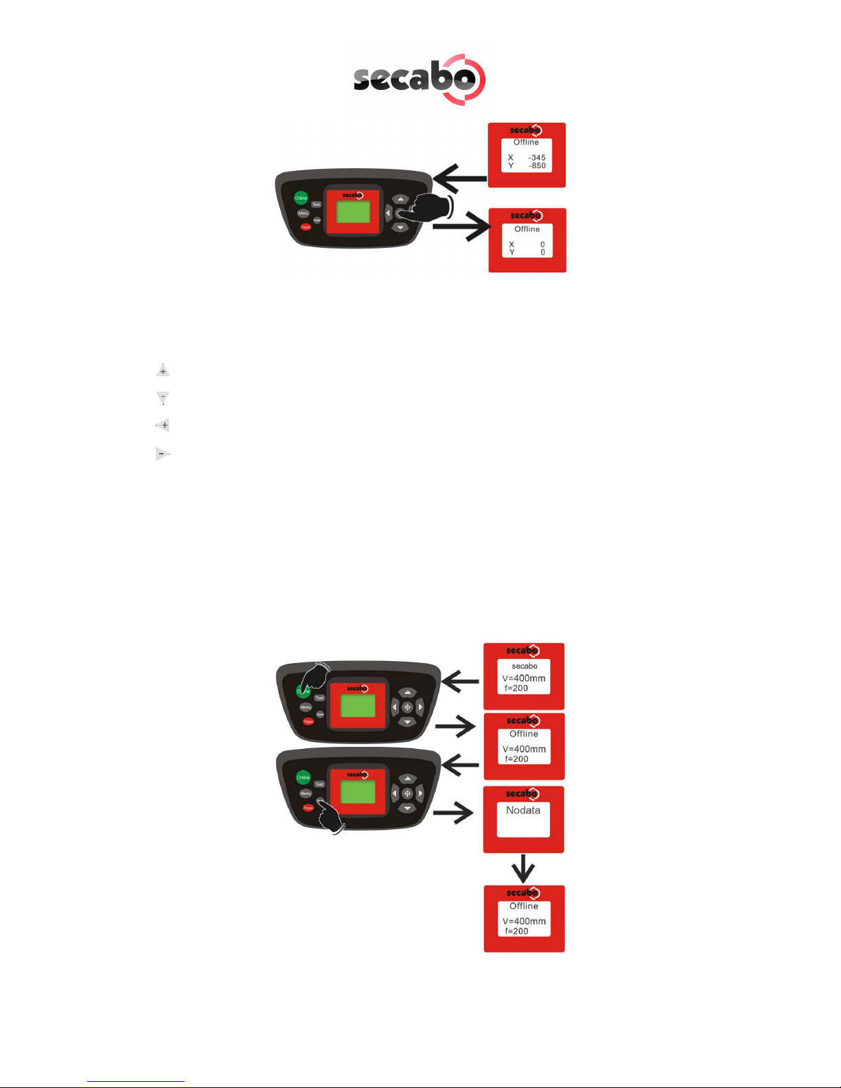
6.2 Moving t e Cutting Head
In the offline mode, the cutting head can be moved to the right and left by pressing
the arrow keys and the foil can be moved forwards and backwards. The
corresponding X and Y coordinates are shown on the display.
6.3 Setting t e Zero Point
Move the cutting head and foil so that the blade is at the front right corner of the
foil to set the correct starting point for plotting. Then confirm this zero point by
pressing the crosshair symbol in the middle of the control panel.
Online
OnlineOnline
Online-Status
Offline
OfflineOffline
Offline-Status
13
6.4 C anging
You can make the following changes in the online mode by pressing the
corresponding buttons:
Increase speed
Reduce speed
Increase pressure
Reduce pressure
The cutting speed and contact pressure cannot be changed while a plotting job is in
progress.
6.5 Repeat Function
After conclusion of a job it can be repeated without having to transfer the data from
the computer again. For this purpose ensure that the vinyl cutter is in the offline
mode and press the Repeat key.

14
6.6 Ot er Settings
It is possible to scroll through other configuration menus in the offline mode by
pressing the menu key a number of times.
In the settings menu it is possible to adjust the idle speed of the cutting head (Ur), as
well as the Baud rate (Br). The Baud rate set must be identical with the Baud rate set
on the computer. This value must be set to 38400.
The vinyl cutter can be calibrated correctly in the scaling menu (Set Per). Correction
may be required here due to wear to the mechanical parts. The X and Y scaling of
the data can be changed by changing the Xp and Yp values. If, for example, an
object entered with a length of 100 cm on the computer is cut on the vinyl cutter to
a length of only 98cm, it is necessary to correct the corresponding scaling value on
the plotter.
Otherwise, these values should not be changed.
6.7 Limit Switc es
If a plotting job is sent to the vinyl cutter accidentally which is larger than the
maximum cutting width of the plotter, the cutting head is stopped automatically by a
sensor at the left and right sides. In this case, the vinyl cutter is reset and it is
necessary to transfer the job to the plotter again.
38400

15
7Drag knifes
Drag knifes are sensitive, sharp and dangerous precision tools.
•Always keep the blades away from children!
•Exercise care when handling blades to prevent injuries.
•Treat the cutting blades carefully and always store them with the associated
protective cap when not in use. If the tip of a blade hits against a hard
material such as glass or stone, tiny chips can be broken out of the tip
rendering the blade unusable.
Please observe the following notes to prevent unnecessar wear to our blades and
achieve the maximum possible service life.
•Always avoid cutting into the backing material on the foil. The wear to the
blades is increased when it is necessary for them to cut deeper into the
material used.
•Adjust the cutting depth of the blade so that the material is just cut through
cleanly. Further extension of the blade reduces its service life and does not
improve the cutting results at all
•Use specially designed blades for thicker material (e.g. flock blades for flock).
•Ragged edges after cutting the foil indicate that the blade is dull. Always
replace dull blades immediately!

16
8Tec nical Data
Model C30III C60III C120III
Type Desktop unit Unit including
stand-up base
Unit including stand-
up base
Max. medium width 415mm 720mm 1300mm
Max. cutting width 305mm 610mm 1220mm
Connections RS232C, USB
Display Back-lighted, 4-line LCD display
Plotter languages HP-GL, DMPL
Memory Unit has 1MB internal memory
Max. speed 600mm/s
Max. medium thickness 1mm
Contact pressure 50g – 500g
Mechanical resolution 0.025mm
Repetition accuracy < ± 0.1mm
Power supply 90V AC – 240V AC/ 50Hz – 60Hz
Ambient conditions + 5C - +35C / 30% - 70% humidity
eight without packing 9kg 12kg 18kg
eight with packing 11kg 16kg 39kg
Dimensions ( x H x D)
585mm x 265mm x
270mm
890mm x 265mm x
270mm
1465mm x 265mm
x 270mm

17
9Troubles ooting
Vin l cutter terminates job with Pause on displa and does not react when buttons
are pressed.
In this case, it is necessary to restart the vinyl cutter to eliminate the error.
Possible causes:
Possible causes:Possible causes:
Possible causes:
•Job transferred in wrong format (too large).
•Settings changed during transfer operation.
•Plotter set to pause during plotting operation to change contact pressure or
speed.
Jobs are alwa s output too large:
Possible causes:
Possible causes:Possible causes:
Possible causes:
•Resolution incorrectly adjusted (increments in mm)
•Output size greater than 100%.
An imported job (EPS) is plotted a number of times at the same position.
Possible causes:
Possible causes:Possible causes:
Possible causes:
File may be corrupted and should be checked.
Straight lines are cut zigzag
Possib
PossibPossib
Possible causes:
le causes:le causes:
le causes:
Blade adjustment and/or contact pressure incorrect and should be checked.
Curves are not cut properla
P
PP
Possible causes:
ossible causes: ossible causes:
ossible causes:
The curve quality setting in the job standard settings in the production manager
is not set to high.

18
Konformitätserklärung
Statement of Conformity
Hiermit erklären wir in alleiniger Verantwortung, dass das unter „9. Technische
Daten“ genannte Produkt mit den Bestimmungen der folgenden EG-Richtlinien und
Normen übereinstimmt:
e herewith declare under sole responsibility that the under „9. technical data“
mentioned product meet the provisions of the following EC Directives and
Harmonized Standards:
EG-Richtlinien / EC Directives:
2006/95/EG Niederspannungsrichtlinie
2006/95/EC Low Volatge Directive
98/37/EG Maschinenrichtlinie (2006/42/EG ab 29.12.2009)
98/37/EC Directive on machinery (from 2009-12-29: 2006/42/EC)
Norm / Standard:
EN 60204-1:2006
Technische Dokumente bei / Technical documents at:
Secabo GmbH, Hochstatt 6-8, 85283 olnzach, Germany
Dipl. Ing. Fabian Franke Dipl. Ing.(FH) Bernhard Schmidt
Secabo GmbH, www.secabo.com, Hochstatt 6-8, 85283 olnzach, Germany
Other manuals for C30III
1
This manual suits for next models
2
Table of contents
Other Secabo Cutter manuals


Popular Cutter manuals by other brands

Formech
Formech FLB1000 Installation, operating and service manual

Dolmar
Dolmar PC-6114 Operator's and safety manual

Huskie Tools
Huskie Tools PRO LINE REC-MK730Y Operator's manual

Martor
Martor SECUNORM 590 instructions

Wolfcraft
Wolfcraft 5018000 instruction manual

Silhouette
Silhouette Portrait Specifications


