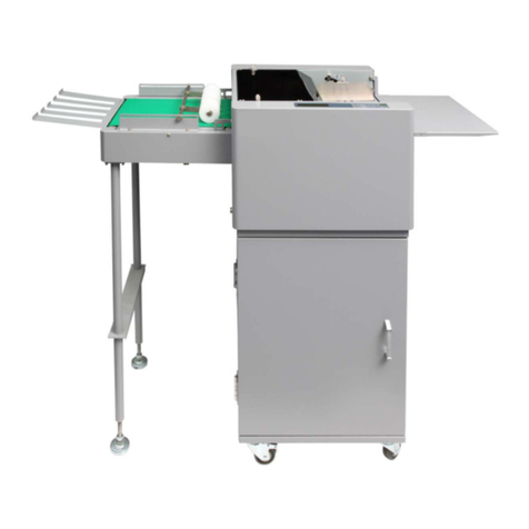
Formax Cut-True 29A User manual

Cut-True 29A & 29H
Guillotine Cutters
OPERATOR MANUAL
11/2016

3
1. GENERAL INFORMATION
This operator manual was written to enable safe operation of machine and
comfortable usage.
Please read information carefully before operating the cutter, with special notes
for safety precautions.
The operator manual must always be available to the person operating the
machine!
The cutter should be operated by one person only!
2. TRANSPORT AND STORING
2.1.Delivery conditions
The cutter will be delivered by manufacturer:
with disassembled base and optional side tables,
assemble according to drawings 1b and 1c
drawing1a. Cutter without side tables

4
drawing 1b. Assembly of side tables
1. side table left + screw M8x25 (4 pcs) + washer 8 (4 pcs)
2. side table right + screw M8x25 (4 pcs) + washer 8 (4 pcs)
3. safety curtain left + screw M8x25 (4 pcs) + washer 8 (4 pcs)+ nut M8 (4 pcs)
4. safety curtain right + screw M8x25 (4 pcs) + washer 8 (4 pcs)+ nut M8 (4 pcs)

5
drawing 1c. Machine base assembly
1. Right leg 1 pcs
2. Left leg 1 pcs
3. Bracket 1 pcs
4. Shelf 1 pcs.
5. Screw M 8x50 8 pcs
6. Screw M 5x16 4 pcs
drawing 1d. Assembled base

6
drawing 1e.
drawing 1f. Placing the cutter on the base

7
1. Transport holder 2 pcs
2. Screw M12x30 4 pcs
3. Guillotine
4. Base
5. Screw M10x16 4 pcs
The machine should be carried and placed on the base by 4 strong
persons.
Danger!
Protect power cable from damage by sharp tools, high temperature and
oil.
2.2. Cutter positioning
drawing 2. Leg adjustment
The machine doesn't need to be fixed to the ground. Correct and safe machine
positioning can be reached by the leg 1 adjustment as shown on the drawing 2.

8
Danger!
The cutter cannot be used without safety curtain!

9
3. TECHNICAL PROFILE
3.1. Intended use
The machine can be used for cutting paper, cardboard and other materials:
plastic, foil, laminate, rubber etc - mainly in printing houses, bookbinding workshops
and offices.
CAUTION! Staples or other hard materials can damage the knife blade!
3.2. Basic data
3.2.1. Technical data
chart 1.
PARAMETER Cut-True 29A / 29H
Maximum pile width (mm) 520
Maximum pile height (mm) 80
Functional depth of back part of pile (mm) 530
Narrow cut (mm)
With false clamp 40
Without
false clamp
25
Power of knife motor drive (kW) 1.5
Power of clamp motor drive (kW) 0.37
Power of backgauge motor drive (kW) 0.18
Power supply 230V
Frequency 60Hz
Power 2 kW
Fuse protection 20A
Noise level (dB) 63.9dB
Net weight(kg) 310

10
3.2.2 Exterior dimensions
Drawings 3a,3b and chart 2 show dimensions of different versions of machines.
drawing 3a. Dimensions of cutter without side tables.

11
drawing 3b. Dimensions of cutter with side tables.
chart 2.
DIMENSION
VALUE
(mm)
A
12
4
5
B 900
C
1
215
D
7
8
0
D1 876
F 400
G
1215
H 1480
H1
15
76

12
4. SAFETY SYSTEMS
4.1 Safety systems installed in the machine:
• Simultaneous two-hand cutting buttons – blade is engaged / released by
pressing two buttons simultaneously
• LED Safety Curtain – photoelectric protective safety barrier
• Cam device – controlling knife upper position.
4.2. Safety Elements
1
3
2
5
54
6
7
7
8
9
drawing 4. Location of protective covers and elements

13
chart 2. Safety Features
Dangerous areas and/or
factors Safety equipment
Identification
Position Drawing
I
ME
CHANICAL
1. Worm gear, lever system of
clamping beam - fixed cover 1,3,4
GM2.2402
GM1.2383-1
2. Motor, belt transmission of
clamping beam drive - fixed cover 3,4 GM1.2383-1
3. Belt gear box of the back gauge
drive mechanism
- fixed cover
- front table
3,4
2
GM1.2383-1
GM2.2409-1
4. Motor, lever system of the blade
drive mechanism
- fixed cover
- front table
3,4
1
2
GM1.2383-1
GM2.2402
GM2.2409-1
5. Movement of the clamping beam
- fixed cover
- LED curtain
1
7
GM2.2402
GM2.2640-0
6. Movement of the back gauge - fixed cover 6 GM2.2640-0
7. Cutting zone
- both hands protecting
device
- LED curtain
- cam mechanism,
controlling the blade stop
in the top position
5
7
9
GM2.2640-0
8. Blade change process
- transport carrier
- special protective
package

14
9. Sharp edges and corners of the
guillotine elements - dulls and rounding
10.
Rough, unequal surfaces
-
precise processing of
details
-varnish coat
II
ELECTRICAL
1. Direct touching of electrical
elements
-basic protection
-electric equipment in
housing
3,4 GM1.2383-1
2. Indirect touching
- additional protection
- continuity of protecting
wire
4.3. Work safety rules
1. Operator training :
• user must be made aware of potential dangers
• clearly identify the operator's duties, and restrict use to only those
who have been trained and authorized
2. Do not use cutter if:
• machine is used contrary to the use or/and cutting dimensions set in manual
guide are exceeded
• the machine is broken
• at least one of the shields has been removed
3. Operators must:
Check the functionality of protective devices:
• two-hand simultaneous cutting buttons (any time before operating the
machine)
• LED safety curtain (any time before operating the machine)
• conduct maintenance and repairs only when the power supply is off

15
5. OPERATION
5.1. Control panel
drawing 5. Controls
1. main power switch
2. safety stop button
3. button locking control system
4. button turning on control system
5. Rotary knife change button, two-position (in some software versions this
button is only on touch screen)
- position 0- working cycle (cutting)
- position 1 - knife change mode active
6. Cutting buttons (simultaneous two-hand operation system)
7. Clamp only button
8. Signaling diodes.

16
- red - control system off
- green - control system on
9. LCD control panel
10. LED safety curtain
5.2 Electric equipment (drawing 6)
Danger!
Turn off power supply with main switch before opening covers!
1. Hinged cover of electric board
2. keylock
1
2
drawing 6. Electric board location

17
6. Power supply
Drawing 7 Nameplate location
Data on the nameplate:
- power supply 230V
- frequency 60 Hz
- power installed kW
- fuse protection 20 A
The data presented on the plate must correspond to the voltage of power
supply network!
Cutter must be grounded!

18
7. PREPARATION FOR USE
Be sure to assemble and place the cutter and stand in a location which will not cause
a safety hazard due to location, power cables or an ungrounded power source.
7.1 Using the cutter
7.1.1 Start-up.
drawing 8. Elements used to power on the cutter.

19
1. Turn the main switch 1 into position on "1"
2. Press green button (2) to the ON position
– LED 3 lights green
- LED 4 lights green
- LED 4 lights red (obstacle inside the protective area of curtain A;
remove obstacle –LED 4 lights green)
7.1.2 Emergency stop of the machine
1. Press button 5
7.1.3 Starting up after emergency stop
1. Unlock button 5 (turn)
2. Press green button 2 „I”
7.2 Backgauge positioning
Danger!
Do not put your hands in the cutting area when the back gauge is
moving!
Back gauge can be positioned by program module 1 or manual crank 2 (drawing 9)
Detailed description of settings can be found in separate Programming Manual
7.2.1 Positioning by manual crank 2
1. press crank 2
2. By rotating the crank move gauge forwards or backwards- the dimension value
changes on the touch panel.

20
diagram 9. Elements controlling back gauge
7.3 Clamping
Danger!
Do not put your hands in the cutting area when clamping!
7.3.1 Pressing the material (before cutting)
1. Press simultaneously cut buttons 1 (drawing 10)
- material is clamped automatically
7.3.2 Pressing the material without cutting
1. Press left cut button 1 and clamp button 2 (drawing 10)
7.3.3 Pressing and keeping the material pressed.
1. Press simultaneously left cut button 1 and clamp button 2
(drawing.10)
2. release button 2

21
3. release button 1 – clamp bar returns to upper position
.
drawing 10. Elements used during clamping.
7.3.4 Clamp force adjustment
The clamp force can be adjusted on the touch panel 3 (drawing 10)
Detailed description of settings can be found in separate Programming Manual
7.3.5 Rules of clamp force adjustment
Clamp force is determined by the type, width and the height of the material to be cut.
Basic rules to follow:
• the taller the pile, the bigger the clamping force
• the wider the cutting width, the bigger the clamping force
• the hardness of a material, the bigger clamping force
Other manuals for Cut-True 29A
2
This manual suits for next models
1
Table of contents
Other Formax Cutter manuals

Formax
Formax Cut-True 29A Owner's manual

Formax
Formax Cut-True 31H User manual

Formax
Formax Cut-True 31H User manual

Formax
Formax FD 125 User manual

Formax
Formax FD 120 User manual

Formax
Formax FD 125 User manual

Formax
Formax Cut-True 29H User manual

Formax
Formax FD 574 User manual
Formax
Formax FD 574 User manual
Popular Cutter manuals by other brands

Alpha Professional Tools
Alpha Professional Tools WBCKIT instruction manual

Land Pride
Land Pride RCFM4014 Operator's manual

Nothern Industrial tools
Nothern Industrial tools 1555811 owner's manual

Powermatic
Powermatic SLR12-700 instruction sheet

Makita
Makita CP100DZ instruction manual

Makita
Makita DCO140 instruction manual