SECO-LARM Electromagnetic Gate Lock with Door Cord
SECO-LARM U.S.A., Inc. 3
Installation (Continued)
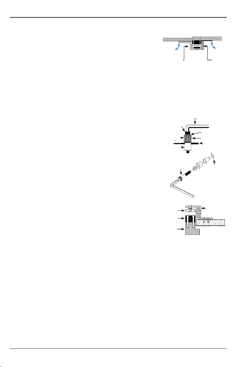
c. Double-swing gate (Fig. 3) – Two gates swing in the same direction
when activated. The electromagnet is fixed to one gate's free end,
and the armature is fixed to the other's free end via a Z-bracket.
IMPORTANT
A cover piece should be added to the Z-bracket as shown in
Fig. 3 to help prevent unauthorized users from prying the armature and the electromagnet apart.
It is important to coordinate the gates' swing to prevent the electromagnet from catching on the
cover piece. The gate with the armature should open before the gate with the electromagnet.
2. Mount the electromagnet. Usually, the electromagnet's position will determine the location of the armature
plate. Make sure there is space to run the cable.
NOTE: For hollow door headers or gate posts, use blind nuts (see Fig. 4)
a. Tape the template to the appropriate location.
b. Drill four 3/8" (9.5mm) holes, one per hex screw.
IMPORTANT: The holes must be precisely 3/8" (9.5mm).
c. Insert a blind nut in one of the 3/8" (9.5mm) holes.
d. Put the washer on the M6x30 hex screw, put the hex tool on the
screw, and turn the screw by hand into the blind nut.
e. Use a wrench or vice-grip to tightly hold the hex tool while using the
included hex key to slowly tighten the hex screw until it does not
turn any further. This compresses the blind nut so that it remains
permanently fixed in the hole. Remove the hex screw and hex tool.
f. Repeat steps c through e for the other blind nuts.
g. Push hex screws into each of the screw holes in the electromagnet.
Use the hex wrench to tighten the screws into the blind nuts.
3. Mount the armature (see Fig. 5). The correct position depends on the
electromagnet's mounted position. Use the appropriate L-bracket or
Z-bracket to position the armature so it lays against the electromagnet
when activated. However, leave a slight gap so the armature does not
slam against the electromagnet when the gate is closed.
a. Put one rubber washer between two steel washers and place them over the armature screw between
the armature and the bracket. This allows the armature to pivot slightly around the armature screw in
order to compensate for gate misalignment.
b. Ensure the guide pins are inserted into guide holes to prevent the armature from spinning.
c. Tighten the sexnut enough so the armature can withstand the force of someone attempting to pry the
gate open while the electromagnet is engaged.
d. Do not tighten the armature against the bracket. The armature must be able to pivot around the
armature screw.
4. Cover the installation. Use a steel box to make the installation more attractive as well as prevent
unauthorized users from prying the armature and electromagnet apart when engaged.
5. Run the wires. The goal is to keep as little of the wires exposed as possible. Use the armored cable
between the electromagnet and the out-of-sight location to protect them from being cut.
6. Open the terminal housing and connect the wires as shown in Wiring Diagram on pg. 4 and test the unit.
7. After all is final, insert the tamper caps into the mounting screw access holes of the electromagnet. This
should be the last step, since, once the tamper caps are in place, they are difficult to remove.
Fig. 3
Fig. 5
(fixed or
adjustable
Fig. 4
3/8" (9.5mm)
hole
(precise size)
Hex screw
(M6x30)
be firmly seated)
(M6x30)