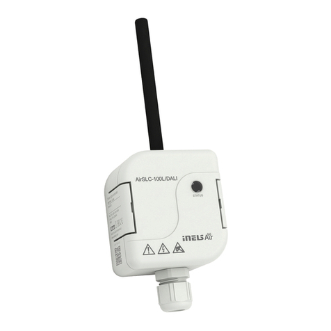
Elko AirSLC-100L/NEMA User manual

1 / 5
AirSLC-100L/NEMA
02-37/2019 Rev.: 0
6
7
4
1
2
8
3
59
1
2
3 4
ELKO EP, s.r.o.
Palackého 493
769 01 Holešov, Všetuly
Czech Republic
Tel.: +420 573 514 211
e-mail: [email protected]
www.elkoep.com
Characteristics
Description
EN
General instrucions
Made in Czech Republic
Cloud app assignment
It is done in your Smartphone application. Enter the relevant information on the product
cover into the application.
Function
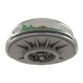
1. Cover
2. Base
3. 0(1)-10 V (+) / DALI (+) *
4. L - phase (LINE)
5. Not connected
6. 0(1)-10 V (-) / DALI (-) *
7. N - neutral (NEUT)
8. V - switched output (LOAD)
9. Not connected
* by module type (analog / DALI)
Underside view
• Used for remote control of the luminaire: ON / OFF / DIMM.
•
Measures current ow - fault detection (ballast fault, light source, connecting
wires ...)
• Communicates over the wireless LPWAN network (LoRa).
• Output signal 0 (1) -10V or DALI for direct control of ballast in luminaire.
• Internal light intensity sensor, range 5 - 100,000Lx.
• Internal temperature sensor in the range -30 ... 70 ° C.
• Power supply: 100-230 V AC, Power 3.5 VA.
• The IP66, UV-resistant, is designed for outdoor mounting in the NEMA socket.
• Update using the RFAF / USB Service Key.
• Connection standard: Standard ANSI C136.41 Dimming Receptacle.
Internet of Things (IoT)
• The IOT wireless communications category describes the Low Power Wide Area
(LPWA). This technology is designed to provide full-range coverage both inside and
outside buildings, energy-saving and low-cost operation of individual devices. The
LoRa network is available to use this standard.
LoRa network information
• The network is bidirectional and its communication uses free frequency band.
• 865 - 867 MHz India
• 867 - 869 MHz Europe
• 902 - 928 MHz North America, Japan, Korea
• The advantage of this network is the possibility of freely deploying individual stations
in local locations, thus strengthening their signal. It can therefore be used eciently in
company premises or, for example, in local parts of cities.
• For more information on this technology, please visit www.lora-alliance.org.
Caution for proper operation:
• Products are installed according to the wiring diagram given for each product.
• For proper device functionality, it is necessary to have sucient coverage of the selec-
ted network at the installation site.
• At the same time, the device must be registered in the network. Successful device re-
gistration on a given network requires a charge for trac.
• Each network oers dierent tari options - it always depends on the number of me-
ssages you want to send from your device. Information on these taris can be found in
the current version of the ELKO EP pricelist.
Street light controller - NEMA socket
When the power is connected, the device sends the initial message containing the meas-
ured temperature and light intensity.
Sensor senses temperature and intensity of lighting every 2 minutes. After that, it sends a
data message of measured values every 15 minutes.
Function setting (message from server):
• Function AUTOMAT:
- the on / o is controlled according to the intensity measured by the light sensor
• Function SEMI-AUTOMAT:
- Switching on / off, the brightness is set according to the set schedule (the schedule
can be set by a message from the server)
- Outside the schedule is set to Auto
• Function MANUAL:
- Messages from the server can be turned on / off, adjust brightness and interval for
sending data messages.
2 / 5
130°
230 V AC L
N
2. 1.
3. 4.
N
L
V
+ 0(1)-10V
- 0(1)-10V
L
N
DALI (+)
DALI (-)
L
N
230 V AC L
N
2. 1.
3. 4.
N
L
V
DALI
Analog
12
Example connection
Assembly
Placement recommendations
Connection 0 (1) -10V (analog)
Connection DALI
Connection
ballast
light source
ballast
light source
1. Remove the protective
layer from the seal and
glue it to the underside of
the AirSLC-100 / NEMA.
2. Place the AirSLC-100/
NEMA into the prepared
socket and turn it clockwi-
se (see LUMAWISE Endu-
rance N, NEMA7 manual
(ANSI C136.41-2013) for
mounting the socket).
• The outdoor lighting control module is designed for
mounting into a ready-made base for public lighting.
• Before mounting, check the range and location of the
product and the antenna. Ensure the correct location -
see Warning.
• The recommended working position is vertical, connec-
tors down.
• Ensure the correct location - see Warning.
• The sensor is suitable for outdoor use. Operating condi-
tions are consistent with conventional chemically non-
aggressive environments.
Connections by TE Connectivity Connector Type:
LUMAWISE Endurance N, NEMA7 (ANSI C136.41-2013)
• For proper functionality, the cover guide should be kept clean and uncovered (occa-
sional cleaning of the cover without the use of chemicals).
Inappropriate location
• Places where distortion may occur (the cover must not be illuminated by direct light)
- below the lamp, where there is a sudden change in lighting intensity (e.g. ashing
advertising), etc.
• Very dusty environment.
• In the case of light pipe installation, the weather may be distorted due to bad weather
(heavy rain / snow).
Description of wiring contacts:
1. 0(1) - 10 V (-)
2. 0(1)-10 V (+)
3. not connected
4. not connected
L (LINE)- phase
N (NEUT) - neutral
V (LOAD) - switched output
Description of wiring contacts:
1. DALI -
2. DALI +
3. not connected
4. not connected
L (LINE)- phase
N (NEUT) - neutral
V (LOAD) - switched output
For the management of DALI BUS there is not an exact cable type recommended, but it is
important to keep some installation conditions. For DALI BUS lines up to 100 m the recommended
min. conductor cross section is 0.5 mm2. For management between 100 m -150 m a cross section
of 0.75 mm2and more than 150 m the recommended min is 1.5 mm2. Management of more than
300 m is not recommended. The voltage drop at the end of the installation may not be greater
than 2 V.

UPLINK
Message Port Byte 0 1 2 3 456789101112
Notication 1Actual
output
level
Actual ballast
status*
Actual
function
status
Heartbeat 2Tempera-
ture[0]
Tempera-
ture[1]
Illumi-
nance[0]
Illumi-
nance[1]
Illumi-
nance[2]
Illumi-
nance[3]
Actual downlink
counter
Power on 3 Version FW Subversion
FW
Version FW
LoRaWAN
Subversion
FW LoRaWAN Actual downlink counter
Conguration conrm 5 0x01
Multicast
conguration conrm 50 Multicast
address [0]
Multicast
address [1]
Multicast
address [2]
Multicast
address [3]
Note
Actual output level 0 - 100 [%]
Actual ballast status*
Bit 0 = 1 ballast not responding
Bit 1 = 1 ballast fault
Bit 2 = 1 lamp fault
Bit 3 = 1 high temperature DALI switching element
Actual function status
Bit 0 = 1 Unknown actual time
Bit 1 = 1 Function MANUAL - timeout overlapped
Bit 5 - 4
Function:
„01“ - AUTOMAT
„10“ - SEMI-AUTOMAT
„11“ - MANUAL
Temperature[0 - 1] x [°C * 10]
Illuminance[0 - 3] 0 - 188000 [lx]
Multicast address [0 - 3] Actual multicast address
* DALI only
DOWNLINK
Message Port Byte 0
Control
1 Requested output level
51 (multicast) Requested output level
Note
Actual output level 0 - 100 [%]
Message Port Byte 0
Status get 2 0xC0
Message Port Byte 0 1 2 3 4 5 6 7 8 9
Conguration 5 Function Heartbeat
period
Initial
output level Ramp Threshold100 Threshold0 Auto Dim Manual
timeout
Manual timeout
value
Manual
timeout status
Note
Function
0x01 Function AUTOMAT
0x02 Function SEMI-AUTOMAT
0x03 Function MANUAL
Heartbeat period
0 - 127 x [min]
129 - 255 x - 128 [h]
Initial output level 0 - 100 [%]
Ramp 0 - 10 [s]
Threshold100 0 - 255 [lx / 10]
Threshold100 < Threshold0
Threshold0 0 - 255 [lx / 10]
Auto Dim
0x00 without diming
0x01 smooth diming
Manual Timeout 1 - 255 x * heartbeat period
Manual Timeout hodnota 0 - 100 [%]
Manual timeout status
0x00 output from Manual timeout value
0x01 output from AUTOMAT
Měření osvětlení
[lx]
Average illumination
value in 20s
Threshold0 Threshold100 0 Lx
Output = 0% „Auto Dim“ == 1
-->
Output = 1 - 99%
Output = 100%
Function AUTOMAT
Checking the current
time
Output controlled by
AUTOMATIC function
Output controlled by
saved plan
• Timestamp (after 10 minutes)
• Day
• Output brightness
< 100% -> change
> 100% -> unchanged
Function SEMI-AUTOMAT
Watching„Manual
Timeout“
Output brightness is
controlled manually by
LoRa messages
OK
Reset timeoutu
„Manual Timeout
Status“
Output controlled by
AUTOMATIC function
Timeout
exceeded
Output =„Manual
Timeout Value“
„0“
„1“
Function MANUAL

Note
Time[0 - 1] 0 - 1439 [min] e.g. 18:20 = 18*60 + 20 = 1100
Day
0x00 Sunday
0x01 Monday
0x02 Tuesday
0x03 Wednesday
0x04 Thursday
0x05 Friday
0x06 Saturday
Note
Time[0 - 1] 0 - 1439 [min] 10 min,
e.g. 18:20 = 18*60 + 20 = 1100
Day (mask)
Bit 0 = 1 Sunday
Bit 1 = 1 Monday
Bit 2 = 1 Tuesday
Bit 3 = 1 Wednesday
Bit 4 = 1 Thursday
Bit 5 = 1 Friday
Bit 6 = 1 Saturday
Requested
output level 0 - 100 [%]
Message 0 1
Device reset 100 0xE1
Message Port Byte 0 - 3 4 - 7 8 - 11
Counters set 101 Uplink counter[3 - 0] Downlink counter[3 - 0] Multicast downlink counter[3 - 0]
Message Port Byte 0 1 2
Actual time set
6 Time[0] [min] Time[1] [min] Day
56 (multicast) Time[0] [min] Time[1] [min] Day
Message Port Byte 0 1 2 3
Time mark set
7 Time[0] [min] Time[1] [min] Day (mask) Requested output level
57 (multicast) Time[0] [min] Time[1] [min] Day (mask) Requested output level
Message Port Byte 0
Time table clear
8 0x00
58 (multicast) 0x00
Message Port Byte 0 1 2 3 45678...
Mutlicast address set 50
0x01 Multicast
address [0]
Multicast
address [1]
Multicast
address [2]
Multicast
address [3] NwksKey[0] AppsKey[0] NwksKey[1] AppsKey[2] ...
0x00 - multicast
cancel
Note
Multicast address [0 - 3] multicast address
NwksKey [0 - 15] NwksKey
AppsKey [0 - 15] AppsKey
CRC[0 - 1] Sum of all bytes + 0x0A0A
Little-Endian
Message Port Byte 0
Multicast address get 51 0x00
Example
Multicast address set
Multicast address 01234567
NwksKey 00112233445566778899AABBCCDDEEFF
AppsKey A0A1A2A3A4A5A6A7A8A9AAABACADAEAF
Final message 50 010123456700A011A122A233A344A455A566A677A-
788A899A9AAAABBABCCACDDADEEAEFFAF1C7A
Cancel multicast address
Final message 50 00
Heartbeat period Time between periodical messages on port 2
Manual timeout Time without receiving the message by the device.
The manual timeout is set in multiples of the heartbeat period.
Heartbeat = 5 min
Manual timeout = 2 Manual timeout = 10 minut
Threshold100 / Threshold0 Enter in lux / 10
100% at 20 lux Threshold100 = 2
0% at 300 lux Threhsold0 = 30

5 / 5
AirSLC-100L/NEMA/
DALI
AirSLC-100L/NEMA/
0-10
WarningTechnical parameters
Read the operating instructions before installing the device and putting it into opera-
tion. Instruction manual is designated for mounting and also for user of the device. It is
always a part of its packing. Installation and connection can be carried out only by a per-
son with adequate professional qualication upon understanding this instruction man-
ual and functions of the device, and while observing all valid regulations. Trouble-free
function of the device also depends on transportation, storing and handling. In case you
notice any sign of damage, deformation, malfunction or missing part, do not install this
device and return it to its seller. It is necessary to treat this product and its parts as elec-
tronic waste after its lifetime is terminated. Before starting installation, make sure that all
wires, connected parts or terminals are de-energized. While mounting and servicing ob-
serve safety regulations, norms, directives and professional, and export regulations for
working with electrical devices. Do not touch parts of the device that are energized – life
threat. To ensure the transmission of the radio signal, make sure that the devices in the
building where the installation is installed are correctly located. Unless otherwise stated,
the devices are not intended for installation in outdoor and damp areas, they must not
be installed in metal switchboards or in plastic cabinets with metal doors - this prevents
transmission of the radio frequency signal. iNELS Air is not recommended for control-
ling life-saving instruments or for controlling hazardous devices such as pumps, heaters
without thermostat, lifts, hoists, etc. - radio frequency transmission may be overshad-
owed by obstruction, interference, transmitter battery may be discharged etc., thereby
disabling the remote control.
Supply voltage::
Power:
Supply voltage tolerance:
Standby consumption:
Consumption max.:
Temperature sensor
Range:
Accuracy:
Light sensor
Scanned Range:
Detection angle:
Indication
- blue LED:
- green LED:
- red LED:
Inputs
Communication Interface:
Relay
Power outputs L, N, V:
Number of contacts:
Current rating:
Breaking capacity:
Switching voltage:
Mechanical life:
Electrical life:
Communication
Protocol:
Transmitter frequency:
Range in open space:
Transmission power (max.):
Protocol:
Transmitter frequency:
Range in open space:
Other parameters
Working temperature:
Storage temperature:
Operation position:
Mounting:
Protection degree:
Overvoltage category:
Pollution degree:
Dimension:
Weight:
AC 100 - 230 V AC
3.5 VA
-10 /+15 %
0.5 W
at 2 W communication
Measurement of instrument internal temperature
-30 .. 70°C
±1°C in the range -10°C .. 70°C
±3°C in the range -30°C .. -10°C
5 - 100 000 Lx
130°
module power supply
STATUS module
LPWAN communications
DALI Analog
p o l a r i z e d - a c t i v e ( 2 0 m A ) 0 ( 1) -10 V ( 2 0 m A )
Load max. 10 A
1x NO AgSnO2
10 A
2500 VA / 300 W
250 V AC1 / 30 V DC
1x 10⁷
1x 10⁵
LoRa
868 MHz
Approx. 10 km*
25 mW / 14 dBm
iNELS RF Control
866 MHz, 868 MHz, 916 MHz
up to 20 m
-30 .. +50 °C
-30 .. +70 °C
See manual
in socket
IP66
III.
2
Ø 84 x 75 mm
150 g
The company ELKO EP, as the manufacturer, is entitled to make technical modications to the
product, in the technical specication and product manual, without prior notication.
* Depending on network coverage
This manual suits for next models
3
Table of contents
Other Elko Controllers manuals

Elko
Elko LIC-1 User manual

Elko
Elko RFWB-20/G User manual

Elko
Elko RFSA-61B User manual

Elko
Elko iNels SA3-022M User manual

Elko
Elko iNELS AirSLC-100NB/NEMA/DALI User manual

Elko
Elko RFDEL-76M User manual

Elko
Elko RFSA-61B User manual

Elko
Elko iNELS RFGB-20 User manual

Elko
Elko inels RFSTI-11B User manual

Elko
Elko iNels RFSAI-161B User manual

Elko
Elko iNels BPS3-02M User manual

Elko
Elko RFDAC-71B User manual

Elko
Elko COS-1 User manual

Elko
Elko Inels AirSLC-100NB/LWES User manual

Elko
Elko RFJA-12B/230V User manual

Elko
Elko RFDAC-71B User manual

Elko
Elko iNELS GSB3-40 User manual

Elko
Elko LIC-2 User manual

Elko
Elko iNels LBC3-02M User manual

Elko
Elko LIC-2 User manual