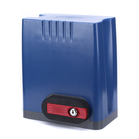
Seco VINCO 600 User manual

Sliding Gate Opener
VINCO
600 - 800 - 1000 - 1500 - 2000 - 2500
MANUAL
Rwww.seco.gr
Tel. 0030 210 9846222
Fax 0030 210 9822276
Agiou Dimitriou 263, TK. 17342, Athens, Greece
ENG GR

Safety Protection and Precautions
THIS SERIES OF DOOR OPENERS MUST BE INSTALLED BY
PROFESSIONALS.
1. ATTENTION! Please operate the machine carefully in strict compliance with
instructions of this Manual. It is very important to personal safety . Incorrect
installation or improper use of the machine may cause serious damage to the person
and/or property.
2. Read this Manual carefully before installation.
3. The installation must comply with relevant national codes and specifications and the
mechanical parts used must meet with national standards.
4. The power supply should have a voltage meeting the requirements of the machine,
be reliably grounded, and have both leakage protection and short circuit protection.
5. Before system overhaul, cut off the power and check if the grounding system is
correct and reliable.
6. The machine must be equipped with safety devices (such as infrared intrusion
protector) (optional) and should be inspected on a frequent basis for normal
operation.
7. We will accept no responsibility for any consequences resulting from inappropriate
use of the machine or from use beyond the specified purposes.
8. We will accept no responsibility for any problem incurred due to neglect of the
process requirements of precision components or due to deformation of such
components during the installation.
9. The product was designed and manufactured in strict compliance with the operating
instructions given in this Manual. Any use or operation against these instructions
may damage the product or bring a hazard.
10. We will accept no responsibility for any safety problem or operation failure caused by
the use of any component not produced by us.
11. Don’t make any change to the components of the system.
12. The installer must explain in detail to the user the operating rules of the machine and
relevant regulations in case of an emergency, and provide the user with the Manual.
13. Keep children and other unauthorized persons away from the installation site and
make sure there is no risk factor existing in the vicinity of the installation site.
14. Clean off any obstacle from the motion route of the door before the electric control
system is put into operation, and stop the flow of vehicles and pedestrians when the
door is in motion.
15. The main control box should be installed in such a position and to such a height that
should be appropriate, ventilated, and properly protected from rain, sunshine,
playing kids, and the operation of remote control and control panel switch by
mistake.
16. An external housing may be added if necessary. In doing so, the shielding effect of
the external housing (usually made of metal) against the receiving of remote control
signals should be taken into account since it may affect the product’s functionality
and bring inconvenience to the user.
17. Keep the remote control out of the reach of children. Failure to do so may incur
accident to children.
18. Don’t try to repair or adjust the system by yourself. Contact professionals instead.
19. Keep the Manual properly for future use.
R
VINCO
Sliding Gate Opener
2

Main Technical Specifications:
Working Principle and Main Components and Functions
The door opener mainly consists of a high-strength aluminum alloy box, a high-quality
single-phase motor, a frictional overrun clutch, a worm-gear reducer, a gear clutch and
an output gear. During the operation, the motor spindle drives both the reducer and
output gear by means of the frictional overrun clutch, and the output gear then push
racks mounted on the sliding door to move the door horizontally so that the door can be
opened and closed in the energized state.
When the special key is turned clockwise, the gear clutch is engaged and the motor
power transmitted by the worm gear drives the output gear to rotate via the gear clutch
so as to drive the rack mounted on the door, pushing the door to move (or to open and
close) horizontally. Meanwhile because of the reverse self-locking feature of the worm
gear mechanism, the door is locked as well, keeping closed against an external force.
When the special key is turned counterclockwise, the left and right parts of the gear
clutch are disengaged from each other and the output gear is freed from the influence of
the motor, allowing the door to be opened and closed manually.
Install the Metal Base
The door opener should be mounted on a metal base with bolts. As for how to install the
metal base, see Fig. 1.
MODEL VINCO 600
Supply Voltage(V)
Motor Power(W)
Torque
Maximum Weight Of Gate
Motor Rotation Speed(Rated)
Gate Speed
Limit Switch
Noise
Operating Environment Temperature
Certicates
MODEL
Supply Voltage(V)
Motor Power(W)
Torque
Maximum Weight Of Gate
Motor Rotation Speed(Rated)
Gate Speed
Limit Switch
Noise
Operating Environment Temperature
Certicates
AC230/120V
280W
20Nm
600kg
1400r/min
12M/Minute
Spring switch/magnetic switch
≤56dB
-45oC - 65oC
CCC, CE
AC230/120V
370W
20Nm
800kg
1400r/min
12M/Minute
Spring switch/magnetic switch
≤56dB
-45oC - 65oC
CCC, CE
AC230/120V
550W
20Nm
1000kg
1400r/min
12M/Minute
Spring switch/magnetic switch
≤56dB
-45oC - 65oC
CCC, CE
AC230/120V
750W
20Nm
1500kg
1400r/min
12M/Minute
Spring switch/magnetic switch
≤56dB
-45oC - 65oC
CCC, CE
AC230/120V
1200W
20Nm
2000kg
1400r/min
12M/Minute
Spring switch/magnetic switch
≤56dB
-45oC - 65oC
CCC, CE
AC230/120V
1500W
20Nm
2500kg
1400r/min
12M/Minute
Spring switch/magnetic switch
≤56dB
-45oC - 65oC
CCC, CE
VINCO 800 VINCO 1000
VINCO 1500 VINCO 2000 VINCO 2500
3
www.seco.gr
Tel. 0030 210 9846222
Fax 0030 210 9822276
Agiou Dimitriou 263, TK. 17342, Athens, Greece

Mount the Rack
The easiest way to install a rack is to place it on the gear teeth of the door opener first,
disengage the door opener, and then push the door slowly to move the tack bit by bit to
the desired position. In this way, you can make sure that the teeth of the rack are
perfectly engaged with the teeth of the gear. When doing so, don’t forget to mark each
mounting point. (See Fig. 2.) Be noted not to lay the entire weight of the door onto the
gear.
Door Opener Release Device (Open the door manually)
The door opener is designed with a lockable release device which enables you to open
the door manually in case of blackout. For the release device and its operations, see
Fig.3 and Fig. 4.
Install the Limit Switch
Install the switch bracket onto the rack by reckoning the final travel position. (See Fig. 5).
For a spring switch, adjust until to an inclination that the spring comes into contact with
the switch flapper. For a magnetic switch, the magnet should point to the motor and be
located according to the position of the magnetic limit switch inside the housing.
SC - SDCB102
Control Panel for Sliding Gate Motors
R
4

For wiring, see Fig. 6
For control panel wiring, see Control Panel Manual.
Energizing & Trial Run
1. Before use, check the power supply voltage, frequency and other data carefully and
make sure they are in line with the requirements, and check if the ground wire is in
good condition and the electrical wiring is correct.
2. A special key is provided along with the shipment of the door opener. Turn the key
counterclockwise (to disengage the clutch), push the sliding door and let the door
opener to operate without load. If the door opener works properly, then turn the key
clockwise (to engage the clutch).
3. Turn on the power, start the door opener, and observe the sliding operation of the
sliding door.
4. Adjust the magnet’s position until the door is able to open and close in positions to
your satisfaction.
Care and Maintenance
1. Apply some antirust grease to the end of the worm gear spindle located inside the
hole of the special key.
2. Check frequently if the electrical grounding is in good condition.
3. Check frequently if all parts and components are in good condition.
4. The device uses advanced lubricant that requires no replacement or replenishment.
www.seco.gr
Tel. 0030 210 9846222
Fax 0030 210 9822276
Agiou Dimitriou 263, TK. 17342, Athens, Greece
5

Possible Faults and Trouble shooting
No. Fault Possible Causes Troubleshooting
1 Motor cannot be started.
No power supply. Check the power supply.
Fuse is blown. Replace the fuse.
Capacitor breaks down. Replace the capacitor.
Overloaded. Check for any obstruction on
the door rail.
Thermal protector is activated. Restart in 20 minutes
Sensor switch is damaged. Replace the sensor switch.
Cable becomes broken, loose
or detached. Connect up the cable.
2
The door can be opened
(closed) but cannot be
closed (opened)
Sensor switch is damaged. Replace the sensor switch.
A/COM/C line is incorrectly
wired.
Connect the line as per the
wiring diagram.
Check controller and motor Check if the line is open.
3 Limit operation fails.
Sensor switch is far apart. Adjust the position
Sensor switch is incorrectly
located.
Magnetic steel become
detached and incorrectly
located.
Sensor switch is damaged Replace the sensor switch.
W, V, or COM line is
incorrectly wired
Connect the line as per the
wiring diagram
4 Manual clutch fails. Clutch lever is damaged. Replace the clutch lever.
Rotation direction is wrong. Rotate in the direction as
indicated.
Clutch gets stuck. Turn left and right to output
R
6

the gear.
5
Press “OPEN” button but
“CLOSE” operation is
activated.
W and V lines are incorrectly
wired.
Connect the line as per the
wiring diagram.
6Motor rotates but the
device doesn't work.
Clutch compression spring
fails or lacks of elasticity. Check, adjust or replace
Clutch is in the disengaged
position. Engage the clutch correctly.
The compression spring of the
friction clutch fails or becomes
loose.
Replace or adjust the spring
pressure.
www.seco.gr
Tel. 0030 210 9846222
Fax 0030 210 9822276
Agiou Dimitriou 263, TK. 17342, Athens, Greece
7

R
Agiou Dimitriou 263, TK. 17342, Athens, Greece
Tel. 0030 210 9846222
Fax 0030 210 9822276
www.seco.gr
This manual suits for next models
5
Table of contents
Other Seco Gate Opener manuals
Popular Gate Opener manuals by other brands

SOMFY
SOMFY MASTER PRO 180 Operating and installation guide

DITEC
DITEC 0DT872 Installation manual, maintenance, use
FAAC
FAAC 415 Series manual
CAME
CAME F7000 instruction manual
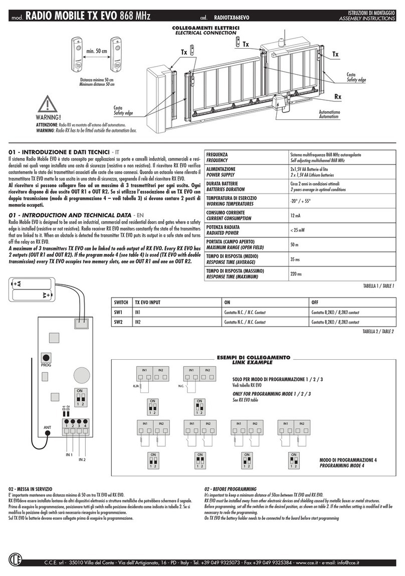
C.C.E.
C.C.E. RADIO MOBILE TX EVO Assembly instructions

La Toulousaine
La Toulousaine Intellidrive 400 Installation & programming manual
GFA
GFA ELEKTROMAT SE 6.80 FU-25,40 installation instructions
GTO
GTO E-Z GATE installation manual
Dea
Dea GULLIVER operating instructions

SOMFY
SOMFY MONOGRAM Motorised Roller/Roman quick start guide
Pro-Line System
Pro-Line System CS300 operating instructions

Chamberlain
Chamberlain MEGA SLIDE-X owner's manual
