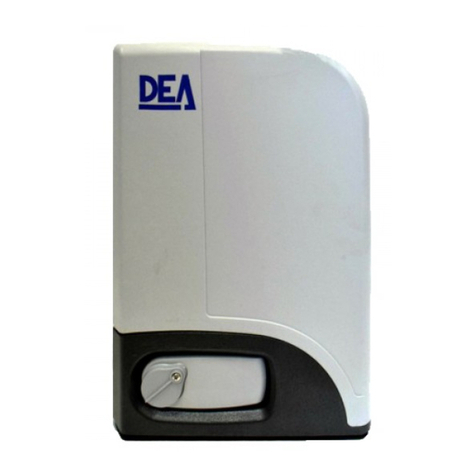
Dea GULLIVER User manual

Operatore elettromeccanico per cancelli scorrevoli industriali
Istruzioni d’uso ed avvertenze
Electromechanical operators for industrial sliding gates
Operating instructions and warnings
Opérateurs électromécaniques pour portails coulissants industriels
Notice d’emploi et avertissements
Elektromechanischer Antrieb für industrielle Schiebetore
Bedienungsanleitung und Hinweise
Operador electromecánico para cancelas correderas industriales
Instrucciones de uso y advertencias
Operador electromecânico para portões de correr industriais
Instruções para utilização e advertências
Napęd elektromechaniczny do przemysłowych bram przesuwnych
Instrukcja montażu i użytkowania
Электромеханические операторы для промышленных раздвижных ворот
Инструкция по эксплуатации и предупреждения
I6130XX Rev. 15 14/12/17


EN-1
GULLIVER
Electromechanical operators for industrial
sliding gates
Operating instructions and warnings
Index
1Warnings Summary EN-1 6Start-up EN-7
2Product Description EN-3 6.1 Installation Test EN-7
3Technical data EN-3 6.2 Unlocking and manual operation EN-7
4Installation and Assembly EN-4 7Maintenance EN-7
5Electrical Connections EN-5 8Product Disposal EN-8
1 WARNINGS SUMMARY
WARNING! ImpoRtANt sAfety INstRuctIoNs. cARefully ReAd ANd folloW All WARNINGs ANd INstRuc
-
tIoNs thAt AccompANy the pRoduct sINce INcoRRect INstAllAtIoN could cAuse hARm to people, ANImAls
oR thINGs. WARNINGs ANd INstRuctIoNs pRovIde ImpoRtANt INfoRmAtIoN ReGARdING sAfety, INstAllAtIoN,
use ANd mAINteNANce. Keep the INstRuctIoNs toGetheR the techNIcAl documeNtAtIoN ANd foR futuRe
RefeReNce.
WARNING The device may be used by children of less than 8 years of age, people with
reduced physical, mental or sensory impairment, or generally anyone without experience
or, in any case, the required experience provided the device is used under surveillance or
that users have received proper training on safe use of the device and are aware of the
dangers related to its use.
WARNING Do not allow children to play with the device, the xed commands or the ra-
dio controls of the system.
WARNING Product use in abnormal conditions not foreseen by the manufacturer may
generate hazardous situations; meet the conditions indicated in these instructions.
WARNING DEA System reminds all users that the selection, positioning and installa-
tion of all materials and devices which make up the complete automation system, must
comply with the European Directives 2006/42/CE (Machinery Directive), 2014/53/UE
(RED Directive). In order to ensure a suitable level of safety, besides complying with local
regulations, it is advisable to comply also with the above mentioned Directives in all extra
European countries.
WARNING Under no circumstances use the device in an explosive atmosphere or in
areas that may be corrosive or could damage product parts. Check that the temperatures
at the installation site are suitable and comply with the temperatures declared on the
product label.
WARNING When working with the “dead man” switch, make sure that there are no pe-
ople in the area where the automatism is being used.
WARNING Check that there is a switch or an omni polar magneto-thermal circuit bre-
aker that enables complete disconnection in case of over voltage category III conditions
installed upstream from the power system.

EN-2
WARNING To ensure an appropriate level of electrical safety always keep the 230V
power supply cables apart (minimum 4mm in the open or 1 mm through insulation) from
low voltage cables (motors power supply, controls, electric locks, aerial and auxiliary
circuits power supply), and fasten the latter with appropriate clamps near the terminal
boards.
WARNING If the power cable is damaged, it must be replaced by the manufacturer or
its technical assistance service or, in any case, by a person with similar qualications to
prevent any risk.
WARNING All installation, maintenance, cleaning or repair operations on any part of
the system must be performed exclusively by qualied personnel with the power supply
disconnected working in strict compliance with the electrical standards and regulations
in force in the nation of installation.
Cleaning and maintenance destined to be performed by the user must not be performed
by unsupervised children.
WARNING Using spare parts not indicated by DEA System and/or incorrect re-assem-
bly can create risk to people, animals and property and also damage the product. For this
reason, always use only the parts indicated by DEA System and scrupulously follow all
assembly instructions.
WARNING Changing the closing intensity could lead to dangerous situations. Therefore,
qualied personnel should only perform increases to the closing force. After adjustment,
compliance with regulatory limits values should be detected with a force impact-mea-
suring instrument. The sensitivity of the obstacle detection may be adjusted gradually
to the door (see programming instructions). The anti-crushing device operation must be
checked after each manual adjustment. Manual modication of the force can only be
done by qualied personnel by performing the measurement test according to EN 12445.
Modications to the force adjustment must be documented in the machine manual.
WARNING The compliance of the internal sensing obstacles device to requirements
of EN12453 is guaranteed only if used in conjunction with motors tted with encoders.
WARNING Any external security devices used for compliance with the limits of impact
forces must be conform to standard EN12978.
WARNING In compliance with EU Directive 2012/19/EU on waste electrical and elec-
tronic equipment (WEEE), this electrical product should not be treated as municipal
mixed waste. Please dispose of the product and bring it to the collection for an appropri-
ate local municipal recycling.
eveRythING thAt Is Not expRessly pRovIded foR IN the INstAllAtIoN mANuAl Is Not AlloWed. coRRect op
-
eRAtoR opeRAtIoN Is oNly eNsued WheN the RepoRted dAtA Is Respected. the compANy does Not RespoNd
foR dAmAGe cAused by fAIluRe to comply WIth the INstRuctIoNs coNtAINed IN thIs mANuAl. WIthout Af
-
fectING the esseNtIAl feAtuRes of the pRoduct, the compANy ReseRves the RIGht to mAKe ANy chANGes
deemed AppRopRIAte ANd At ANy tIme IN oRdeR to techNIcAlly, stRuctuRAlly ANd commeRcIAlly ImpRove
the pRoduct WIthout beING RequIRed to updAte thIs documeNt.

EN-3
2 PRODUCT DESCRIPTION
Models and contents of the package
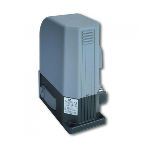
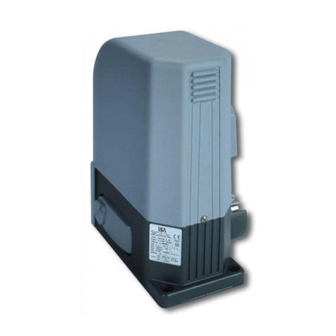
The name GULLIVER identies a series of electromechanical operators for industrial sliding gates with different features as to motor
and control board power supply voltage, capacity, mechanical adjustment of force and built-in limit switch.
GULLIVER is completed by a set of accessories listed in the “PRODUCT ACCESSORIES” table (page I-6). This operator is composed of
a mechanical gear motor which rotates the driving gear; This gear, coupled to the rack properly installed on the gate, converts the circular
motion of the gear motor into rectilinear motion thus allowing the movement of the gate on its own guide.
Inspect the “Contents of the Package” (Pic. 1) and compare it with your product for useful consultation during assembly.
Transport
GULLIVER is always delivered packed in boxes that provide adequate protection to the product, however, pay attention to all informa-
tion that may be provided on the same box for storage and handling.
3 TECHNICAL DATA
18NET - 18NET/M - 18/IB - 1503E 25RRT - 25RRTF - 25RRT/M - 25/IB
Motor power supply voltage (V) 230 V ~ ±10% (50/60 Hz) 400 V ~ ±10% (50/60 Hz)
Absorbed power (W) 560 1200
Max Thrust (N) 1300 1650
Duty cycle (cycles/hour) 15 (leaf L=12m) 17 (leaf L=14m)
Maximum n° of operations in 24 hour 240 280
Built-in capacitor (µF) 30 -
Operating temperature range (°C) -20 ÷ 50 °C
Motor thermal protection (°C) 140 °C -
Opening speed (m/min) 10 10
Weight of product with package (Kg) 30
Sound pressure emitted (dBA) < 70
Protection degree IPX4
NET230N
Power supply (V) 230 V ~ ±10% (50/60 Hz)
Fuse F2 (A) 5A
Fuse F1 (A) 160mA
230V operators outputs 2 x 600W
Auxiliaries power supply output 24 V ~ (24V_AUX + 24V_ST = max 200mA)
Safety devices power supply output 24V
“Warning” output 230 V ~ max 150W
Electric lock output max 1 art. 110 or 24V output max 5W congurable
230V Flashing light output 230 V ~ max 40W
24V Flashing light output 24 V max 100mA (for led ashing light) art. LED24AI or
open gate warning light/courtesy light
Operating temperature range (°C) -20÷50 °C
Receiver frequency 433,92 MHz
Transmitters type of coding HCS x-code - HCS rolling code - Dip-switch
Max remote controllers managed 100
OPERATOR
CONTROL BOARD

EN-4
4 INSTALLATION AND ASSEMBLY
4.1 For a satisfactory installation of the product is important to:
• Ensure that the facility complies with current regulations and then dene the full project of the automatic opening;
• Ensure that throughout the course of the gate, while opening and closing, there are no friction points;
• Ensure that there is no danger of derailment and that there are not risks that it goes out of the guides;
• Make sure the gate is in equilibrium: it must not move if it stays in any position;
• Ensure that the mounting area of the motor allows the release and a manual operation easier and safer;
• Ensure that the mounting positions of the various devices are protected from impacts and the surfaces are sufciently robust;
• Do not allow the automation parts are immersed in water or other liquids.
4.2 Dened and satised these prerequisites, proceed to the assembly:
If the supporting plane is already available, the xing of the motor must be done directly on the surface using, for example screw
anchors or chemical means.
Alternatively, proceed as follows:
• Make a hole appropriate to the type of land by using as a reference the measurements shown in Fig 3;
• Provide an adequate number of channels for the passage of electrical cables;
• Place the base of the foundation;
• Start casting of concrete and, before you start taking, bringing the base plate to the dimensions shown in Figure 4, making sure that
is parallel to the gate wing and perfectly level. Wait for the complete setting of the concrete;
If the rack is already present, place the pinion at a distance of 1-2 mm in order to avoid that the weight of the wing could burden
on the gear motor (Fig. 5). To do this, adjust the height of GULLIVER shimming the base in an appropriate manner and then tighten the
locking screws in a robust way (Fig. 6).
Alternatively, proceed as follows:
• Unlock the motor and fully open the door;
• Place the rst section of the rack on the wing, making sure that the start of the rack corresponds to the top of the wing. Then attach
the rack to the leaf keeping a game of 1-2 mm from the pinion (Fig. 5);
• Cut off the excess part of the rack;
• Finally, move the door manually several times and verify that the alignment and the distance of 1-2 mm between the rack and pinion
is respected throughout the length;
• Tighten the locking screws of GULLIVER in a robust way (Fig. 6) and cover with plastic caps.
4.3 How to unlock the operator
Once you open the lock on the handle (protected by a plastic cover), the lever must be turned in the direction shown in Fig. 7, at this
point the operator is unlocked and the gate, in the absence of other obstacles is free in his movements. The reverse process, turn the
lever until it stops and closing of the lock (remember to protect the lock with the proper cover), keeps GULLIVER in working condition.
4.4 Limit-switches
Adjustment of the limit-switches
Some GULLIVER models provides a limit-switch whose intervention must be adjusted for each installation. DEA System provides two limit
switches cams (Fig. 8) that are installed on the rack of the gate and subsequently regulated in such a way as to ensure the functionality
and safety distances in opening and closing of the gate.
Keep in mind that when the limit switches trigger, the door will move to another 2-3 cm, and it’s therefore suggested to x the end of
stroke brackets at a sufcient distance from the mechanical stops.
Adjustment of the magnetic limit switch
Attach the mounting brackets to the magnets as shown in Figure 10, making sure to mount the LIGHT BLUE magnet at the closing limit
switch, the GREEN magnet at the end of the opening limit switch (Fig. 11). Connect the cable of the magnetic sensor which is colored
BROWN at the FCC 1 input (Closing Limit Switch 1) and the BLACK one at FCA 1 input (Opening Limit Switch 1) (Fig. 12);
WARNING Refer to control board instructions to correctly identify the limit switch inputs.
WARNING Incorrect installation of the magnets can be dangerous to people or things; observe the conditions prescribed in these
instructions.
Mount the magnetic sensor as shown in Fig. 9. The sensor must protrude from the bracket for supporting at least 35mm, in this way will
avoid any interference.
Adjust the magnets support brackets so as to maintain a distance from the sensor between 10 and 20mm;
WARNING Opening and closing magnets positions are referred to a standard installation (operator placed on the left of the gate). In
case of use of the parameter P063 (NET control boards only) for an inverted installation (operator on the right), the position of the
magnets must not be changed.
In case of combination with the control panel art. 400RR, and only if you have to reverse the direction of travel of the geared motor,
you will have to manually reverse the limit switch cables.
EN-5
WARNING The electrical connections in this manual refer exclusively to the NET series control boards. If you are using GULLIVER
with control board 212E or 400RR, please refer to the user manual of those control boards for all the wiring needed to startup the
motor.
5 ELECTRICAL CONNECTIONS
Run the motor connections following the wiring diagrams.
WARNING For adequate electrical safety, keep low safety voltage wires (controls, electro-locks, antenna, auxiliary power) clearly separate
from 230V ~ power wires (minimum 4 mm in air or 1 mm via supplementary insulation) placing them in plastic raceways and securing
them with adequate clamps near terminal boards.
WARNING For connection to the mains, use a multipolar cable having a minimum section 3x1,5 mm² and complying with the current
regulations. For connecting the motors, use a minimum cross section 1,5 mm² cable and complying with the current regulations. As
an example, if the cable is out side (outdoor), must be at least equal to H05RN-F, whereas if it (in a raceway), must be at least equal to
H05VV-F.
WARNING All wires must be striped and unsheathed in the immediate vicinity of terminals. Keep wires slightly longer to subsequently
eliminate any excess.
WARNING Maintain the ground conductor at a major length respect the active conductors so that, if the cable exit from its xing housing,
the active conductors tighten up as rst.
WARNING To connect the encoder to the control panel, use only a dedicated cable 3x0,75mm2.
Program the control board to complete all adjustments. It is now possible to supply a complete installation in compliance with all stan-
dards required for gate automation. See the instructions provided with the control panel to be connected.
Finally, verify that all adjustments operations have been correctly performed and that safety devices and unlocking device properly
work.

EN-6
2
1
9 10 11 12 13 14 15 16
17
18
19
20
21
22
23
24
25
26
27
28
30 2932 31
3 4 5 6 7 8
WARNING LOCK
F2F1
FLASH
230V
MOT 1 MOT 2
34 33
WL/FL24V
2 x 0,5 mm2
To terminal 31/32 for normal connection
To terminal 33/34 for controlled safety devices
N.O.
N.O.
PED
N.C.
FCA1
N.C.
RG58
N.C.
START
FCC1
TX RX
PHOTO 1
2 x 1 mm2
2 x 0,5 mm2
2 x 0,5 mm2
2 x 0,5 mm2
2 x 0,5 mm2
2 x 0,5 mm2
2 x 0,5 mm2
2 x 0,5 mm2
ENC
M1
F
N
F
N
LED230AI
max 40W
FLASH
230V
3 x 0,22 mm
2
4 x 1,5 mm2
3 x 1,5 mm2
COM
N.C.
N.O.
2 x 0,5 mm2
INTERNAL WIRING SET BY THE FACTORY
EXTERNAL WIRING SET BY THE INSTALLER
OPEN GATE WARNING LIGHT
230V max 150W
BROWN
BLACK
GRAY
OMNIPOLAR CIRCUIT BRAKER
POWER SUPPLY
230V~ 50Hz ±10%
SAFETY (Only if needed)
Brown
Blue
Black
Blue
COM
IN_1
COM
IN_2
COM
IN_3
COM
IN_4
COM
IN_5
COM
IN_6

EN-7
6 START-UP
The start-up phase is very important to ensure maximum security and compliance to regulations, including all the requirements of EN
12445 standard which establishes the test methods for testing the automation for gates.
DEA System reminds that all installation, maintenance, cleaning or repair operations on any part of the system must be performed
exclusively by qualied personnel who must be responsible of all texts requie by the eventual risk;
6.1 Installation test
The testing operation is essential in order to verify the correct installation of the system. DEA System wants to summarize the proper
testing of all the automation in 4 easy steps:
• Make sure that you comply strictly as described in paragraph 2 “WARNINGS SUMMARY”;
• Test the opening and closing making sure that the movement of the leaf match as expected. We suggest in this regard to perform
various tests to assess the smoothness of the gate and defects in assembly or adjustment;
• Ensure that all safety devices connected work properly;
• Perform the measurement of impact forces in accordance with the standard 12445 to nd the setting that ensures compliance with
the limits set by the standard EN12453.
WARNING Using spare parts not indicated by DEA System and/or incorrect re-assembly can create a risk to people, animals and
property and also damage the product. For this reason, always use only the parts indicated by DEA System and scrupulously follow all
assembly instructions.
6.2 Unlocking and Manual operation
In the event of malfunctions or simple power failure, release the motor (Pic. 7) and perform the operation manually.
The knowledge of the unlocking operation is very important, because in times of emergency the lack of timeliness in acting on such
a device can be dangerous.
WARNING The efcancy and safety of manual operation of the automation is guaranteed by DEA System only if the installation has
been installed correctly and with original accessories.
7 MAINTENANCE
Good preventive maintenance and regular inspection ensure
long working life. In the table below you will nd a listo f inspections/
maintenance operations to be programmed and executed periodi-
cally.
Consult the TROUBLE-SHOOTING” table whenever anomalies are
observed in order to nd the solution to the problem and contact
DEA System directly whenever the solution required is not provided.
INTERVENTION TYPE PERIODICITY
cleaning of external surfaces 6 months
checking of screw tightening 6 months
checking of release mechanism operation 6 months
electric brake cleaning 6 months
TROUBLE-SHOOTING
Description Possible solutions
When the opening or closing command is activated the
gate leaf fails to move and the operator’s electric motor
fails to start.
The operator is not receiving correct power supply. Check all connections, fuses, and the
power supply cable conditions and replace or repair if necessary. If the gate does not close
check the correct functioning of photocells.
When the opening command is activated, the motor starts
but the gate leafs fail to move.
Check that the unlocking system is closed (see Pic. 7).
Check the electronic force adjustment device and the mechanical clutch.
Make sure that the motor does not push in the opposite direction, the limit switch electrical
connections might be reversed.
The gate moves by ts and starts, it is noisy, it stops at half
run or it does not start.
Make sure that nothing hinders the gate wheels movement and the slide in which they roll.
There always must be backlash between rack and pinion; make sure the rack is accurately
positioned.
The power of the gearmotor may be insufcient for the characteristics of the gate’s wing;
check the choice of model whenever requiredh.
If the operator attachment to the gate bends or is badly fastened, repair and/or buttress it.

EN-8
8 PRODUCT DISPOSAL
GULLIVER consists of materials of various types, some of which can be recycled (electrical cables, plastic, aluminum, etc. ..) while
others must be disposed of (electronic boards and components).
Proceed as follows:
1. Disconnect the power supply;
2. Disconnect and disassemble all the accessories connected. Follow the instructions in reverse to that described in the section “Installa-
tion”;
3. Remove the electronic components;
4. Sorting and disposing of the materials exactly as per the regulations in the country of sale.
WARNING In line with EU Directive 2012/19/EU for waste electrical and electronic equipment (WEEE), this electrical product must
not be disposed of as unsorted municipal waste. Please dispose of this product by returning it to your local municipal collection
point for recycling.

I-1
Pos. Descrizione - Description - Description - Beschreibung - Descripción - Descrição - Opis - Описание
1Colonnina Pilly 60 - Pilly 60 column - Colonnette Pilly 60 - Kleine Säule Pilly 60 - Columna Pilly 60 - Coluna Pilly 60 - Kolumienka Pilly 60 - Pilly 60 столбик
2 GULLIVER
3Fotocellule - Photocells - Photocellules - Fotozellen - Fotocélulas - Fotocélulas - Fotokomórki - фотоэлементы
4Safety edge - Bord sensible - Berührungssensible Schaltleiste - Borde sensible - Dispositivo sensível de protecção - Listwa bezpieczeństwa - Ребро
безопасности
5Lampeggiante - Flashing light - Clignotant - Blinker - Lámpara - Intermitente - Lampa Ostrzegawcza - Сигнальная лампа
6Selettore a chiave antiscasso - Anti lock-picking key switch - Sélecteur à clé anti-intrusion - Einbruchfester Schlüsselschalter - Selector a llave antisabo-
taje - Interruptor de chave burglar - Przełącznik kluczowy wandaloodporny - Замковый выключатель
7Radiocomando - Remote-control - Radiocommande - Funksteuerung - Radiocomando - Comando via rádio - Nadajnik - Пульт ДУ
8Selettore digitale - Radio keypad - Digicode radio - Digitalwahlschalter - Teclado digital radio - Teclado via radio - Bezprzewodowa klawiatura - Радио
кодовая панель
A
4x1 mm² (230V) o 3x1,5 mm² (24V) - 6 x 0,5 mm²
4x0,5 mm²
2 x 0,5 mm² - RG58
2x0,5 mm²
4x0,5 mm²
2x0,5 mm²
3x0,5 mm²
2x0,5 mm²
B
Collegarsi alla rete 230 V ± 10% 50 Hz tramite un interruttore onnipolare o altro dispositivo che assicuri la onnipolare disinserzione della rete, con una
distanza di apertura dei contatti ≥ 3 mm - Make the 230V ± 10% 50 Hz mains connection using an omnipolar switch or any other device that guarantees
the omnipolar disconnection of the mains network with a contact opening distance of 3 mm - Connectez-vous au réseau 230 V ± 10% 50 Hz au moyen
d’un interrupteur omnipolaire ou d’un autre dispositif qui assure le débranchement omnipolaire du réseau, avec un écartement des contacts égal à 3
mm. - Den Anschluss an das 230 V ~ ± 10% 50 Hz Netz mit einem Allpolschalter oder einer anderen Vorrichtung vornehmen, durch die eine allpolige
Netzunterbrechung bei einem Öffnungsabstand der Kontakte von ≥ 3 mm gewährleistet wird. - Efectuar la conexión a una línea eléctrica 230 V ± 10%
50 Hz a través de un interruptor omnipolar u otro dispositivo que asegure la omnipolar desconexión de la línea, con 3 mm de distancia de abertura de
los contactos. - Ligue na rede de 230 V ± 10% 50 Hz mediante um interruptor omnipolar ou outro dispositivo que assegure que se desliga de maneira
omnipolar da rede, com abertura dos contactos de pelo menos 3 mm. de distância - Podłączyć się do sieci 230 V ± 10% 50 Hz poprzez przełącznik
jednobiegunowy lub inne urządzenie które zapewni brak zakłóceń w sieci, przy odległości między stykami ≥ 3 mm. - Подключайтесь к сети 230V ±
10% 50 Гц с помощью многополюсного выключателя или используйте любое другое устройство, которое гарантирует многополюсное отключение
питающей сети с расстоянием между контактами от ≥ 3 мм и больше.
Collegare a terra tutte le masse metalliche - All metal parts must be grounded - Connectez toutes les masses métalliques à la terre - Alle Metallteile
erden - Conectar con la tierra todas las masas metálicas - Realize ligação à terra de todas as massas metálicas - Uziemić wszystkie elementy metalowe.
- Все металлические части должны быть заземлены.
Esempio di installazion tipica - Example of typical installation - Exemple d’installation typique - Installationsbeispiel - Ejemplo de
instalación típica - Exemplo de instalação típica - Przyład standardowego systemu automatyzacji - Пример типового монтажа
DEA System fornisce queste indicazioni che si possono ritenere valide per un im-
pianto tipo ma che non possono essere complete. Per ogni automatismo, infatti,
l’installatore deve valutare attentamente le reali condizioni del posto ed i requisiti
dell’installazione in termini di prestazioni e di sicurezza; sarà in base a queste
considerazioni che redigerà l’analisi dei rischi e progetterà nel dettaglio l’auto-
matismo. - DEA System provides the following instructions which are valid for a
typical system but obviously not complete for every system. For each automatism
the installer must carefully evaluate the real conditions existing at the site. The
installation requisites in terms of both performance and safety must be based
upon such considerations, which will also form the basis for the risk analysis and
the detailed design of the automatism. - DEA System fournit ces indications que
vous pouvez considérer comme valables pour une installation-type, même si elles
ne peuvent pas être complètes. En effet, pour chaque automatisation, l’installa-
teur doit évaluer attentivement les conditions réelles du site et les pré-requis de
l’installation au point de vue performances et sécurité ; c’est sur la base de ces
considérations qu’il rédigera l’analyse des risques et qu’il concevra l’automatisa-
tion d’une manière détaillée. - Diese Angaben von DEA System können als gül-
tig für eine Standardanlage angesehen werden, können aber nicht erschöpfend
sein. So muss der Installationsfachmann für jedes Automatiksystem sorgfältig die
Voraussetzungen des Installationsortes sowie die Leistungs- und Sicherheitsan-
forderungen an die Installation abwägen; aufgrund dieser Überlegungen muss
er die Risikobewertung erstellen und genau das Automatiksystem entwickeln. -
DEA System facilita estas indicaciones que pueden considerarse válidas para
una instalación tipo pero que no pueden considerarse completas. El instalador,
en efecto, tiene que evaluar atentamente para cada automatismo las reales con-
diciones del sitio y los requisitos de la instalación por lo que se reere a presta-
ciones y seguridad; en función de estas consideraciones redactará el análisis de
riesgos y efectuará el proyecto detallado del automatismo. - DEA System fornece
estas indicações que podem ser consideradas válidas para o equipamento pa-
drão, mas que podem não ser completas. Para cada automatismo praticamente
o técnico de instalação deverá avaliar com atenção as condições reais do sítio
e os requisitos da instalação em termos de performance e de segurança; será
em função destas considerações que realizará uma análise dos riscos e projec-
tará. - DEA System dostarcza wskazówek, do wykorzystania w typowej instalacji
ale nie będą one nigdy kompletne. Dla każdego typu automatyki, instalator musi
sam oszacować realne warunki miejsca montażu i wymogi instalacyjne mając na
uwadze przepisy dotyczące bezpieczeństwa. Na podstawie zebranych informacji
będzie w stanie przeanalizować zagrożenia mogące wystąpić i zaprojektować w
szczegółach automatyzację. - DEA System предлагает рекомендации , которые
действительны для типовой системы , но , очевидно, не обязательны для каждой
конкретной установки. Для каждого конкретного случая установщик должен
тщательно оценить реальные условия. Устройства для установки оцениваются
с точки зрения производительности и безопасности, которые необходимы для
анализа рисков и детального проектирования системы автоматизации.

I-2
245
115
402
325

I-3
105 mm.
117 mm.
20 mm.
Base di fondazione, Foundation
plate, Plaque de fondation,
Fundamentplatte, Placa de cimenta-
ción, Placa de fundação, Płyta
fundamentowa, Закладная пластина
Anta cancello, Door gate,
Leaf, Schiebetor, Hoja, Folha,
Brama, Створка ворот
Cremagliera, Rack,
Crémaillère,
Zahnstange, Cremal-
lera, Cremalheira,
Zębatka, Зубчатая
рейка
Struttura fissa,
Fixed structure,
Structure fixe,
Wand, Estructura
fija, Estrutura fixa,
Stała struktura,
Зафиксированно
е основание
Pozzetto in cemento,
Concrete shaft, Enveloppe
de béton, Betonschacht,
Fuste de hormigón, Eixo de
concreto, Wał betonowy,
Бетонный фундамент
Cavi, Cables, Câbles,
Verdrahtung, Cables,
Cabos, Kable, Кабели
20
150
450
350
60
334
205

I-4
1÷2 mm

I-5
min 35
Pos. Description Pos. Description
1
Azzurro, light blue, bleu,
hellblau, azul, niebieski,
светло-голубой
2Verde, green, vert, grün,
verde, zielony, зеленый
P063 = 000 P063 = 001
ATTENZIONE: In caso di utilizzo del parametro P063 (solo centrali serie NET) per l’installazione invertita del motore (motore a destra), la posizione dei
magneti non deve essere modificata. - WARNING: In case of use of the parameter P063 (NET control boards only) for an inverted installation (operator
on the right), the position of the magnets must not be changed. - ATTENTION: En cas d’utilisation du paramètre P063 (seulement pour platines de la
série NET) pour l’installation du moteur inversé (à droite), la position des aimants ne doit pas être modifiée. - ACHTUNG: Bei Verwendung des Parame-
ters P063 (nur bei Steuerungen der Baureihe NET) für die umgekehrte Installation des Motors (Motor rechts) darf die Magnetenposition nicht verändert
werden. - ATENCION: En caso se utilice el parámetro P063 (solo cuadros de la serie NET) para la instalación del motor al otro lado (motor a la derecha),
la posición de los imanes no debe ser modificada. - ATENÇÃO: No caso de utilizar o parâmetro P063 (apenas centrais de comando NET) para uma
instalação invertida (motor no lado direito), a posição dos magnetos não pode ser alterada. - UWAGA: W przypadku zastosowania parametru P063 (tylko
centrale sterujace serii NET), przy odwróconej instalacji silnika (silnik z prawej), położenie magnesów nie musi być zmieniane. - ВНИМАНИЕ: В случае
использования параметра P063 (только для платы NEТ) для зеркальной установки (привод справа), положение магнитов следует поменять местами
вручную.

I-6
A
B
C
Centrale di Comando
Control Board
Pos. Description
ANero, Black, Noire, Schwarz,
Negro, Preto, Czarny, черный FCA 1
BBlu, Blue, Bleu, Blau, Azul, Nie-
bieski, Cиний COM
C
Marrone, Brown, Marron,
Braun, Marrón, Marrom, Brąz,
коричневый
FCC 1
Tabella “ACCESSORI PRODOTTO”, Table “PRODUCT ACCESSORIES”, Tableau “ACCESSOIRES PRODUITS”,
Tabelle „PRODUKTZUBEHÖRTEILE”, Tabla “ACCESORIOS PRODUCTO”, Tabela “ACESSÓRIOS DO PRODUTO”,
Tabell “AKCESORIA DODATKOWE”, Таблица “АКСЕССУАРЫ ИЗДЕЛИЯ”.
Article
Code
Descrizione, Description, Description, Beschreibung
Descripción, Descrição, Opis, Описание
111
619000
Cremagliera in NYLON, NYLON rack, Crémaillère NYLON, Zahnstange
aus NYLON, Cremallera NYLON, Cremalheira NYLON, Listwa zębata
NYLONOWA, Нейлоновая зубчатая рейка
112
126001
Cremagliera ZINCATA 22x22, ZINC PLATED rack 22x22, Crémaillère
ZINGUÉE 22x22, Eisenzahnstange verzinkt 22x22, Cremallera GALVA-
NIZADA 22x22, Cremalheira ZINCADA 22x22, Listwa zębata METALO-
WA do spawania 22x22, Зубчатая рейка оцинкованная 22x22
113
126000
Cremagliera ZINCATA 30x12, ZINC PLATED rack 30x12, Crémaillère
ZINGUÉE 30x12, Eisenzahnstange verzinkt 30x12, Cremallera GAL-
VANIZADA 30x12, Cremalheira ZINCADA 30x12, Listwa zębata META-
LOWA do przykręcenia 30x12, Зубчатая рейка оцинкованная 30x12

INSTRUCTIONS FOR THE FINAL USER
This guide has been prepared for the nal users of the automatism; the installer is required to deliver this gui-
de and illustrate its contents to the person in charge of the system. The latter must then provide similar instruc-
tion to all the other users. These instructions must be carefully conserved and easily available for consultation
when required.
Good preventive maintenance and frequent inspection ensures the long working life of the product. Contact
the installer regularly for routine maintenance and in event of anomaly.
SAFETY RULES
1. Always keep a safe distance from the automatism during operation and never touch any moving part.
2. Prevent children from playing near the automatism.
3. Perform the control and inspection operations prescribed in the maintenance schedule and immediately stop
using the automatism whenever signs of malfunction are noted.
4. Never disassemble parts of the product! All maintenance and repair operations must be performed only by
qualied personnel.
5. The release operation must sometimes be performed in emergencies! All users must be instructed on the use
of the release mechanism and the location of the release keys.
GULLIVER RELEASE MECHANISM
All GULLIVER models have an unlocking system; the working of this system is the following: after unlocking the
lock on the handle (protected by a plastic cover) turn the lever in the direction shown in gure; the operator is now
unlocked and, if no obstructions hinder its movement, the gate can now move freely. The opposite procedure,
that is the rotation of the lever up to the limit switch and the locking of the lock (remember to protect the lock with
the appropriate cover) returns GULLIVER to its normal working conditions.
WARNING: During this operation gate may present uncontrolled movement: operate with extra care so to
avoid any risk.
CLEANING AND INSPECTIONS
The only operation that the user can and must do is to remove branches, leaves, and any other object that
might obstruct the gate’s free movement. Warning! Always disconnect the power supply whenever performing
operations on the gate!
DEA SYSTEM S.p.A. - Via Della Tecnica, 6 - ITALY
36013 PIOVENE ROCCHETTE (VI)
tel. +39 0445 550789 - fax +39 0445 550265

EUDeclarationofConformity(DoC)
andDeclarationofIncorporationof"quasi‐machines"(pursuanttotheMachineryDirective2006/42/CE,Att.II,B)
Companyname:DEASYSTEMS.p.A.
Postaladdress:ViaDellaTecnica,6
PostcodeandCity:36013PioveneRocchette(VI)‐ITALY
Telephonenumber:+390445550789
declarethattheDoCisissuedunderoursoleresponsibilityandbelongstothefollowingproduct:
Apparatusmodel/Product:18NET‐18NET/M‐18/IB‐1503E‐25RRT‐25RRTF‐25RRT/M‐25/IB
Type:GULLIVER
Electromechanicaloperatorsforindustrialslidinggates
Batch:Seethelabelonthebackoftheusermanual
TheobjectofthedeclarationdescribedaboveisinconformitywiththerelevantUnionharmonisationlegislation:
Directive2006/42/CE(MDDirective)
•Itisdeclaredthattherelevanttechnicaldocumentationhasbeendrawn‐upincompliancewithattachmentVIIB.
•Itisalsodeclaredthatthefollowingessentialhealthandsafetyrequirementshavebeenrespected:1.1.1‐1.1.2‐1.1.3‐1.1.5‐1.2.1‐1.2.6‐1.3.1‐1.3.2‐
1.3.3‐1.3.4‐1.3.7‐1.3.9‐1.5.1‐1.5.2‐1.5.4‐1.5.5‐1.5.6‐1.5.7‐1.5.8‐1.5.10‐1.5.11‐1.5.13‐1.6.1‐1.6.2‐1.6.4‐1.7.2‐1.7.3‐1.7.4‐1.7.4.1‐1.7.4.2‐
1.7.4.3.
•Theundersigneddeclaresthattheafore‐mentioned“partly‐completedmachinery”cannotbecommissioneduntilthefinalmachine,intowhichithasbeen
incorporated,hasbeendeclaredcompliantwiththeMachineryDirective2006/42/CE.
•Ondulyjustifiedrequest,themanufacturercommitstotransmittingtheinformationregardingthe“partly‐completedmachinery”tothenationalauthorities
withoutprejudicetotheirintellectualpropertyrights.
Theproductisincompliancewiththeapplicablepartsofthefollowingregulations:
EN13241‐1:2003+A1:2011;EN12445:2002;EN12453:2002;EN12978:2003+A1:2009
Directive2014/53/UE(REDDirective)
Directive2011/65/EU(RoHS)
Thefollowingharmonisedstandardsandtechnicalspecificationshavebeenapplied:
Title:Dateofstandard/specification
EN61000‐6‐22005+EC:2005
EN61000‐6‐32007+A1:2011
EN301489‐1v2.1.12017
EN301489‐3v2.1.12017finaldraft
EN60335‐12012+EC:2014+A11:2014
EN622332008
EN300220‐1v3.1.12017
EN300220‐2v3.1.12017
EN505812012
Additionalinformation
Signedforandonbehalfof:
Revision:Placeanddateofissue:Name,function,signature
00.03PioveneRocchette(VI)
09/10/17
TizianoLievore
(Administrator)


DEA SYSTEM S.p.A.
Via Della Tecnica, 6 - 36013 PIOVENE ROCCHETTE (VI) - ITALY
tel: +39 0445 550789 - fax: +39 0445 550265
Internet: http:\\www.deasystem.com - E-mail: deasystem@deasystem.com
Table of contents
Other Dea Gate Opener manuals

Dea
Dea LIVI Product manual

Dea
Dea LIVI 403E - 6NET Product manual

Dea
Dea Spazio Series Product manual

Dea
Dea Ghost 100 Series Product manual

Dea
Dea LIVI 803E - 9NET Product manual

Dea
Dea Look Series Product manual

Dea
Dea Ghost 100 Series Product manual

Dea
Dea LIVI 3/24 Product manual

Dea
Dea REV Product manual

Dea
Dea LIVI 500 Product manual
Popular Gate Opener manuals by other brands

Cardin Elettronica
Cardin Elettronica SL Series instruction manual

SOMFY
SOMFY Elixo 500 3S io installation instructions

GATEXPERT
GATEXPERT PY1200AC user manual

Casanoov
Casanoov HICKER B200 manual

Telcoma Automations
Telcoma Automations FLASH 220 quick start guide

Motorline professional
Motorline professional LINCE 300 User’s and Intaller’s manual