CAME F7000 User manual

Documentazione
Tecnica
S55
rev. 1.1
02/2003
©
CAME
CANCELLI
AUTOMATICI
119DS55
SERIE FAST |
FAST SERIES
|
SÉRIE FAST |
BAUREIHE FAST
|
SERIE FAST
F7000 - F7001
CANCELLI AUTOMATICI
AUTOMAZIONE ESTERNA A BRACCI SNODATI PER CANCELLI A BATTENTE
EXTERNAL AUTOMATION SYSTEM WITH ARTICULATED ARMS FOR HINGED GATES
AUTOMATISME EXTERIEUR A BRAS ARTICULES POUR PORTAILS A BATTANT
ÄUSSERE AUTOMATISMUS MIT GELENKIGEN ARMEN FÜR FLÜGELTOREN
AUTOMATIZACIÓN EXTERNA CON BRAZOS ARTICULADOS PARA PUERTAS CON BISAGRAS
Installation type
1 - Motorédecteur
Accessoires:
2 - Armoire de
commande
3 - Récepteur radio
4 - Antenne
5 - Clignotant de
mouvement
6 - Selectueur à clé
7 - Photocellules de
sécurité
8 - Colonnes pour
photocellules
Standardanlage
1 - Getriebemotor
Zubehör:
2 - Schalttafel
3 - Funkempfänger
4 - Antenne
5 - Blinkleuchte “Tor in
Bewegung”
6 - Schlüsselschalter
7 - Lichtschranken
8 - Säule für
Lichtschranken
Instalación estándar
1 - Motorreductor
Accesorios:
2 - Cuadro de mando
3 - Radiorreceptor
4 - Antena
5 - Lámpara
intermitente
de movimiento
6 - Selector con llave
7 - Fotocélulas de
seguridad
8 - Columnas para
fotocélulas
Installation type
1 - Gear motor
Accessories:
2 - Control panel
3 - Radio receiver
4 - Antenna
5 - Flashing light
indicating door
movement
6 - Key-operated selector
switch
7 - Safety photocells
8 - Column for photocells
Impianto tipo
1 - Motoriduttore
Accessori:
2 - Quadro comando
3 - Ricevitore radio
4 - Antenna
5 - Lampeggiatore di
movimento
6 - Selettore a chiave
7 - Fotocellule di
sicurezza
8 - Colonnine per
fotocellule
Impianto tipo
Standard installation
Installation type
Standard Montage
Instalación tipo
1
1
3
2
45 6 7 7
7
7
8
8
LOCK
UNLOCK
CAME
4 x 1
2 x 1
3 x 1,5
230 V
2 x 1,5
RG58
4 x 1,5
2 x 1
2 x 1
TX
RX
RX
TX
LOCK
UNLOCK
CAME
4 x 1
CAME

2
Descrizione:
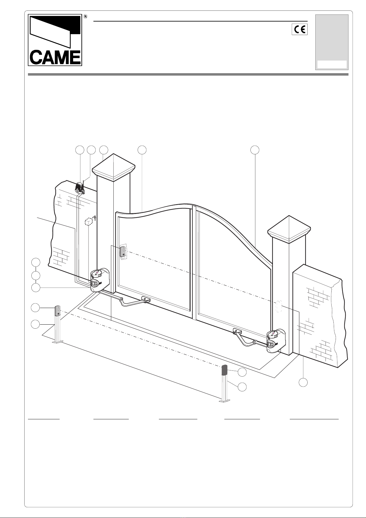
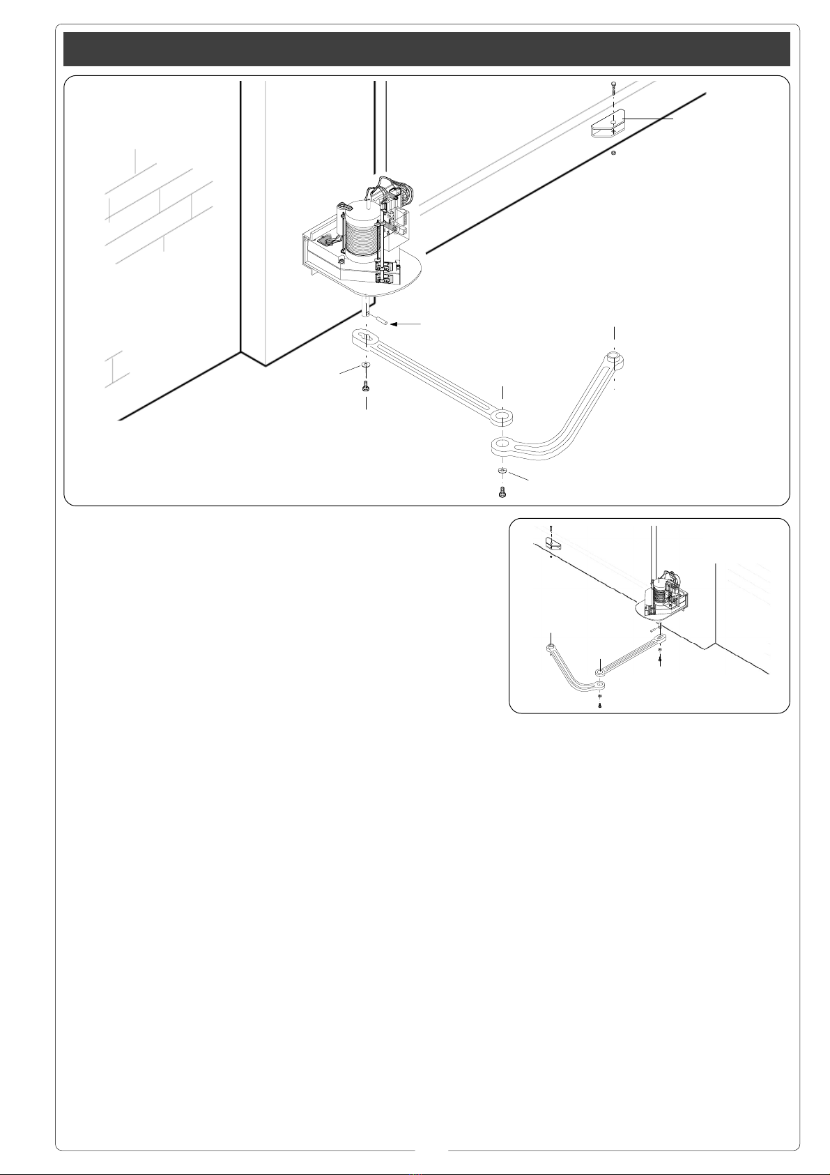
- Automazione esterna a braccio snoda-
to per cancelli a battente.
- Progettato e costruito interamente dal-
la CAME CANCELLI AUTOMATICI
S.p.A., risponde alle vigenti norme di si-
curezza, con grado di protezione IP 54.
- Garantito 24 mesi salvo manomissioni.
Attenzione! Controllate che le apparecchiature di comando, di sicurezza e gli accessori siano originali CAME; ciò garantisce e rende
l'impianto di facile esecuzione e manutenzione.
Accessori opzionali:
H 3000
Dispositivo di sblocco a cordino (L= 5
m.) completo di contenitore di sicurez-
za, manopola di sblocco e pulsante.
LOCK 81
Elettroserratura di blocco a cilindro sin-
golo.
LOCK 82
Elettroserratura di blocco a cilindro dop-
pio.
CARATTERISTICHE GENERALI
ITALIANO
Versioni:
F 7000
Motoriduttore irreversibile 230V a.c. -
160W con quadro elettrico incorporato.
F 7001
Motoriduttore irreversibile 230V a.c. -
160W.
Limiti d'impiego:
- Dimensione ante fino a max. 2,3 metri
(vedi tabella a pag. 4).
- Apertura dell’anta: max. 110°.
Description:
- External automation system with
articulated arm for hinged gates.
- Designed and constructed entirely by
CAME CANCELLI AUTOMATICI S.p.A.
in compliance with current safety
standards, and with an IP54 protecting
rating.
- Guaranteed for 24 months, unless
tampered with by unauthorized
personnel.
Optional accessories:
H 3000
Cable-operated (lenght 5 m.) manual
release system, complete with safety
housing, release knob and pushbutton.
LOCK 81
Single-cylinder electric lock.
LOCK 82
Double-cylinder electric lock.
GENERAL SPECIFICATIONS
ENGLISH
Versions:
F 7000
230V a.c. - 160W irreversible gearmotor
with integrated electric panel.
F 7001
230V a.c.- 160W irreversible gearmotor.
Limits of use:
- Lenght of gate wings: up to max. 2,3
metres (see table on page 4).
- Max. angle of gate wing when open:
110°.
Description:
- Automatisme exterieur a bras articules
pour portails a battant.
- Il a été entièrement concu et construit
par la Société CAME CANCELLI AUTO-
MATICI S.p.A., conformément aux
normes de sécurité en vigueur avec
degré de protection IP 54.
- Il est garanti 24 mois sauf en cas
d'altérations..
Accessoires en optionopzionali:
H 3000
Dispositif de déblocage par cordelette
(L= 5 m.) comprenant le coffret de
sécurité, bouton de déblocage et le
bouton-poussoir.
LOCK 81
Serrure électrique de blocage à barillet
unique.
LOCK 82
Serrure électrique de blocage à double
barillet.
CARACTERISTIQUES GENERALES
FRANÇAIS
Versions:
F 7000
Motoréducteur irréversible 230V a.c. -
160W avec tableau électrique incorporé.
F 7001
Motoréducteur irréversible 230V a.c. -
160W.
Limites d'utilisation:
- Dimension des vantaux jusqu'à max.
2,3 mètres (voir tableau en page 4).
- Ouverture du vantail: max. 110°.
Attention! to insure easy installation and conformance with current safety norms, we raccomend installation of CAME safety and
control accessories.
Attention ! Vérifiez que l’appareillage de commande, de sécurité et les accessoires sont des produits originaux CAME afin de garantir
l’installation et d’en faciliter le montage et l’entretien.

3
Baschreibung:
- Äussere Automatismus mit gelenkigen
Armen für Flügeltoren.
- Vollkommen von der CAME CANCEL-
LI AUTOMATICI S.p.A. den geltenden
Sicherheitsnormen entsprechend
entwickelt und hergestellt. Schutzklasse
IP54.
- Garantie: 24 Monate, vorbehaltlich
unsachgemäßer Handhabung und
Montage.
Extrazubehör:
H 3000
Seilentriegelungsvorrichtung (L = 5 m.)
mit Schutzgehäuse, Entriegelungs
Rebel und Drucktaster.
LOCK 81
Elektroscloß mit Einfachzylinder.
LOCK 82
Elektroscloß mit Doppelzylinder.
ALLGEMEINE MERKMALE
DEUTSCH
Ausführungen:
F 7000
Nicht reversibler Getriebemotor 230V
Wechselstrom - 160W mit eingebauter
Schalttafel.
F 7001
Nicht reversibler Getriebemotor 230V
Wechselstrom - 160W.
Einsatzgrenze:
- Torflügelabmessungen bis zu max.
2,3m. (siehe tabelle auf seite 4).
- Torflügel-Öffnungswinkel: max. 110°.
Descripción:
- Automatización externa con brazo
articulado para puertas con bisagras.
- Diseñado y fabricado enteramente por
CAME CANCELLI AUTOMATICI S.p.A.,
cumple con las normas de seguridad
vigentes, con grado de protección IP54.
- Garantizado 24 meses, salvo
manipulaciones.
Modelos:
Accesorios complementarios:
H 3000
Dispositivo de desbloqueo mediante
cuerda (L= 5 m.) dotato de contenedor
de seguridad, pomo de desbloqueo y
pulsador.
LOCK 81
Cerradura eléctrica de bloqueo a cilin-
dro individual.
LOCK 82
Cerradura eléctrica de bloqueo a cilin-
dro doble.
CARACTERISTICAS GENERALES
ESPAÑOL
F 7000
Motorreductor irreversible 230V c.a. -
160W con cuadro eléctrico incorporado.
F 7001
Motorreductor irreversible 230V c.a. -
160W.
Limites de empleo:
- Dimensión puertas fino a max. 2,3 me-
tri (vedi tabella a pag. 4).
- Apertura de la puerta: max. 110°.
Caratteristiche tecniche // Technical features // Caractéristiques technique // Technische Daten // Descripción técnica
- Dati relativi ai valori di alimentazione nominale - * Regolabile mediante quadri comando CAME.
- Data refers to nominal power supply - * Can be adjusted using CAME control panels.
- Données relatives aux valeurs d’alimentation nominale - * Réglable au moyen des armoires de commande CAME.
- DAten der Stromversorgungsnennwerte - * Ûber CAME-Sreuergeräte regelbar.
- Datos relativos a los valores de la tensión nominal. - * Ajustable mediante los cuadros de mando CAME.
TIPO
TYPE
TYPE
TYP
TIPO
PESO
WEIGHT
POIDS
GEWICHT
PESO
ALIMENTAZIONE
POWER SUPPLY
ALIMENTATION
STROMVERSORG-
UNG
ALIMENTACIÓN
CORRENTE
NOMINALE
NOMINAL CURRENT
COURANT NOMINAL
NENNSTROM
CORRIENTE
NOMINAL
POTENZA MOTORE
MOTOR POWER
PUISSANCE
MOTEUR
WIRKLEISTUNG
MOTOR
POTENCIA MOTOR
INTERMIT. LAVORO
DUTY CYCLE
INTERM. TRAVAIL
EINSCHALTDAUER
INTERM. TRABAJO
COPPIA
TORQUE
COUPLE
DREHMOMENT
PAREJA MOTOR
CONDENSATORE
CAPACITOR
CONDENSATEUR
KONDENSATOR
CONDENSADOR
F 7000 11,6 Kg. 230V a.c. 1,4 A 160 W 30 % *180 N.m 10 µF
F 7001 9,8 Kg 230V a.c. 1,4 A 160 W 30 % *180 N.m 10 µF
Achtung! Wir empfehlen original CAME-Schalt- und -Sicherheitsvorrichtungen mit entsprechendem Zubehör zu montieren, um die
einwandfreie Montage und die problemlose Wartung der Anlage zu gewährleisten.
Atención! Comprobar que los equipos de mando, de seguridad y los acesorios sean originales CAME; lo cual garantiza y facilita el
uso y el mantenimiento del aparato.

4
Larghezza anta
Width of gate wing
Largeur du vantail
Torbreite
Ancho hoja
Peso anta
Weight of gate wing
Poids du vantail
Torg ewic ht
Peso hoja
1 m 300 Kg
1,5 m 250 Kg
2 m 215 Kg
2,3 m 200 Kg
194 mm 218 mm
245 mm
Prima di procedere
all’installazione
dell’automatismo,
controllare che:
- la struttura del
cancello sia
adeguatamente
robusta, le cerniere
siano efficienti e che
non vi sia attrito tra
parti fisse e mobili;
- il percorso dei cavi
elettrici sia eseguito
secondo le
disposizioni di
comando e
sicurezza (vedi
impianto tipo).
- ci sia una battuta
d’arresto meccanico
in chiusura (ben
fissata al suolo) per
evitare l’oltrecorsa
anta/motoriduttore.
Before proceeding
with the installation of
the automatism,
check the following:
- the structure of the
door must be suffi-
ciently sturdy, the
hinges must be effi-
cient and there must
be no friction between
fixed or mobile parts;
- the path of the elec-
trical cables must be
made according to the
control and safety re-
quirements (see the
system type);
- there must be a me-
chanical stop ledge
for door closing (fixed
firmly to the ground)
to prevent the door/
gearmotor from
overextending.
Misure di ingombro e limiti d'impiego // External dimensions and operating limits // Mesures d'encombrement limites
d'utilisation // Außenabmessungen und Einsatzbeschränkungen // Dimensiones máximas y limites de empleo
Prima dell'installazione ... // Before installing ... // Avant d'installer l'automatisme ... // Vor den installation überprüfen ... //
Antes de instalar el automatismo ...
Avant d’installer
l’automatisme,
contrôler:
- si la structure de la
grille est
suffisamment robu-
ste, si les charnières
sont efficaces et s’il
n’y a pas de
frottement entre les
parties fixes et
mobiles;
- si le parcours des
câbles électriques
respecte les
dispositions de
commande et de
sécurité (voir
installation type);
- s’il y a une butée
mécanique d’arrêt
en fermeture (bien
fixée au sol) pour
éviter l’extra-course
vantail/
motoréducteur.
Antes de comenzar
con la instalación
del automatismo,
controle que:
- la estructura de la
cancela sea robusta,
las bisagras
funcionen bien y
que no haya roces
entre las partes fijas
y móviles;
- la colocación de
los cables eléctricos
sea ejecutado según
las disposiciones de
mando y seguridad
(véase instalación
tipo).
- haya un tope de
parada mecánico en
el cierre (fijado
firmemente al piso)
para evitar el
sobrerrecorrido de
la hoja/
motorreductor.
Vor der Installation
vom Automatikantrieb
kontrollieren, ob:
- die Struktur vom Tor
auch ausreichend
stabil ist, die
Scharniere gut
funktionieren und es
keine Reibung
zwischen fest
montierten und
mobilen Teilen gibt;
- die Stromkabel auch
wirklich so verlegt
worden sind, wie für
Steuerung und
Sicherheit
vorgeschrieben ist
(siehe Anlagentyp);
- es einen
mechanischen, gut am
Boden befestigten
Torstopper in der
Offenstellung vom Tor
gibt, der verhindert,
daß der Torflügel/
Getriebemotor über
den Anschlag
hinauslaufen.
C
A
B
330
330
i
Cerniera
Hinge
Charnière
Scharnier
Bisagra
Battuta d'arresto
Mechanical stop
Butée d'arrêt
Anschlag
Tope de parada
i= 240 mm. max
con apertura a 90°
with 90° opening angle
avec ouverture à 90°
mit 90°-Öffnungwinkel
con apertura a 90°
Pilastro
Pillar
Piller
Pleifer
Pilar
Angolo di apertura
Opening angle
Angle d'ouverture
Öffnungswinkel
Ángulo de apertura
A B C
90° 137÷210 0 430
90° 137÷205 50 430
90° 137÷200 75 430
90° 137÷195 100 430
90° 137÷190 125 430
90° 137÷185 150 400
90° 137÷180 175 400
90° 137÷175 200 400
110° 180÷210 0 430
110° 200÷205 50 430

5
Applicazione della piastra-base e della staffa “A” // Application of the basis-plate and of the stirrup // Application de la
piastre-guide et de l’étrier // Montage der Führungsschienen-Basis und des Steigbügels // Applicacion placa base y estribo “A”
- Fissare la piastra-
base al pilastro con
viti M8 e tasselli ø14
rispettando la quota
minima di 100 mm.
dalla pavimentazio-
ne.
- Fissare la staffa
“A” (con viti M6 o
saldatura) all’anta
del cancello rispet-
tando le quote di C
(vedi tabella a
pagina 4) e 68 mm.
- Use M8 screws and
ø14 screw anchors to
mount the base plate
on the pillar. Be sure
to respect the 100
mm. minimum
distance from the
pavement.
- Attach bracket “A” to
the gate wing (use M6
screws or wlds). Be
sure to respect the
offsets of C (see table
page 4) and 68 mm.
- Fixer la plaque de
base au pilier à
l’aide de vis M8 et
tampons ø14 en
respectant la cote
minimum de 100
mm. du sol.
- Fixer l’étrier “A”
(avec des vis M6 ou
par soudure) sur le
vantail du portail en
respectant les cotes
de C (voir tableau
page 4) et 68 mm.
- Die Grundplatte mit
Schrauben M8 und
Dübeln ø14 auf einer
Mindesthöhe von 100
mm. über dem Boden
am Pfeiler befestigen.
- Bügel “A” (mit
Schrauben M6 oder
Schweißung) unter
Einhaltung der Maße
C (sehen Tabelle
Seite 4) und 68 mm.
- Fijar la placa base
al pilar con tornillos
M8 y tacos ø14
respetando la cota
mínima de 100 mm.
del suelo.
- Fijar el estribo “A”
(con tornillos M6 o
saldadura) en la
puerta respetando
las cotas de C
(vedas tabla pag. 4)
y 68 mm.
Vista frontale
Front view
Vue de face
Vorderanssicht
Vista frontal
ø 14ø 14
ø 14ø 14
ø 14
Piastra base
Base plate
Plaque de base
Grundplatte
Placa base
Staffa “A”
Bracket “A”
Etrier “A”
Bügel “A”
Estribo “A”
M8M8
M8M8
M8
M6M6
M6M6
M6
C
100 mm min.
68 mm
116
173
40
96.5
60
100
25.5
==
ø6.5

6
Installazione // Installation // Installation // Installation // Instalación
Aprire il tappo
copriserratura (1).
Inserire la chiave
spingerla e ruotarla
in senso orario (2).
Sollevare il coper-
chio, allentare la vite
Ø 3,9x13 e togliere il
coperchio dal
gruppo
motoriduttore (3).
Inserire il
motoriduttore nella
piastra-base in
corrispondenza dei 4
fori e fissarlo con le
due viti M8x90 e
relativi dadi M8 in
dotazione (4).
Open the lock cover
cap (1).
Push the key in and
turn clockwise (2).
Raise the cover,
loosen the Ø 3.9x13
screw and remove the
cover from the
gearmotor unit (3).
Insert the gearmotor
in the base-plate in
correspondence with
the 4 holes and se-
cure it with the two
M8x90 screws and re-
lated M8 nuts pro-
vided (4).
Enlever le bouchon
qui recouvre la
serrure (1).
Introduire la clé, la
pousser et la
tourner dans le sens
des aiguilles d’une
montre (2).
Soulever le petit
couvercle, desserrer
la vis Ø 3,9x13 et
enlever le couvercle
du groupe
motoréducteur (3).
Placer le
motoréducteur dans
la plaque de base en
correspondance des
4 trous et le fixer à
l’aide des deux vis
M8x90 et des écrous
M8 correspondants
fournis de série (4).
Die Schloßabdeckung
(1) aufmachen.
Den Schlüssel ins
Schloß stecken und
im Uhrzeigersinn (2)
drehen.
Die kleine Abdeckung
anheben, die
Schraube Ø 3,9x13
lösen und die
Abdeckung von der
Einheit mit
Getriebemotor (3)
abnehmen.
Den Getriebemotor so
auf die Grundplatte
setzen, daß die vier
Löcher übereinstimm-
en, und mit den
beiden mitgelieferten
Schrauben M8x90
und den dazugehörig-
en Muttern M8 (4)
befestigen.
Abra el tapón que
cubre la cerradura
(1).
Introduzca la llave,
empújela y gírela ha-
cia la derecha (2).
Levante la tapa, aflo-
je el tornillo Ø 3,9x13
y quite la tapa del
grupo motorreductor
(3).
Coloque el
motorreductor en la
placa de base, ha-
ciendo coincidir los
4 orificios y fíjelo
con los dos tornillos
M8x90 y las tuercas
M8 (4) respectivas
suministradas.
M8x90M8x90
M8x90M8x90
M8x90
M8M8
M8M8
M8
(4)
(1) Ø3,9x13Ø3,9x13
Ø3,9x13Ø3,9x13
Ø3,9x13
(1) (2) (3)

7
Applicazione del braccio snodato // Application of the articulated arm // Application du bras articulé // Anbringung vom
Gelenkarm // Aplicación del brazo articulado
- Inserire la spina
Ø10x40 e il braccio
diritto nell’albero del
motoriduttore e fis-
sarlo con la vite
M10x14 e relativa ro-
setta Ø10x35. Lubri-
ficare il perno del
braccio diritto. Unire
e fissare i due bracci
con la vite M6x10 e
relativa rosetta
Ø6x24. Sbloccare il
motoriduttore e fis-
sare il braccio curvo
alla staffa “A” con la
vite M12x40 ed il re-
lativo dado M12 veri-
ficandone il libero
scorrimento. Per ap-
plicazione a destra ve-
dere fig. 2.
- Insert the Ø10x40
pin and the straight
arm into the shaft of
the gearmotor and se-
cure it with the
M10x14 screw and re-
lated Ø10x35 washer.
Lubricate the pin of
the straight arm. Join
and secure the two
arms with the M6x10
screw and related
Ø6x24 washer. Re-
lease the ratiomotor
and fix the curved arm
to the bracket “A” with
the M12x40 screw
and the related M12
nut, checking its free
sliding. For application
on the right-hand side
see fig. 2.
- Introduire la
cheville Ø10x40
ainsi que le bras
droit dans l’arbre du
motoréducteur et le
fixer à l’aide de la
vis M10x14 et de la
rondelle Ø10x35
correspondante.
Lubrifier le pivot du
bras droit. Unir et
fixer les deux bras à
l’aide de la vis
M6x10 et de la ron-
delle Ø6x24
correspondante.
Débloquer le
motoréducteur et
fixer le bras
recourbé à la bride
“A” à l’aide de la vis
M12x40 et de l’écrou
M12 correspondant
en contrôlant s’il
coulisse correcte-
ment. Voir la fig. 2
pour l’application à
droite.
Den Stecker Ø 10x40
und den geraden Arm
in die Welle vom
Getriebemotor
stecken und mit der
Schraube M10x14
und der dazugehörig-
en Unterlegscheibe Ø
10x35 befestigen. Den
Zapfen vom geraden
Arm abschmieren. Die
beiden Arme mit der
Schraube M6x10 und
der dazugehörigen
Unterlegscheibe Ø
6x24 verbinden und
befestigen. Den
Getriebemotor
entriegeln und den
gebogenen Arm mit
der Schraube M12x40
und der dazugehörig-
en Mutter M12 am
Bügel A befestigen.
Dabei darauf achten,
daß der Arm frei
laufen kann. Für die
Anbringung auf der
rechten Seite siehe
Abb. 2.
- Introduzca el perno
Ø10x40 y el brazo
recto en el árbol del
motorreductor y fíje-
lo con los tornillos
M10x14 y la arande-
la respectiva
Ø10x35. Lubrique el
perno del brazo rec-
to. Una y fije los dos
brazos con el torni-
llo M6x10 y la aran-
dela respectiva
Ø6x24. Desbloquee
el motorreductor y
fije el brazo curvo al
estribo “A” con el
tornillo M12x40 y la
tuerca M12 respecti-
va, comprobando
que se deslice libre-
mente. Para aplica-
ción a la derecha,
véase fig. 2.
Fig. 2
M6x10M6x10
M6x10M6x10
M6x10
M12x40M12x40
M12x40M12x40
M12x40
M12M12
M12M12
M12
ø 6x24ø 6x24
ø 6x24ø 6x24
ø 6x24
ø 10x35ø 10x35
ø 10x35ø 10x35
ø 10x35
M10x14M10x14
M10x14M10x14
M10x14
SpinaSpina
SpinaSpina
Spina
ø 10x40ø 10x40
ø 10x40ø 10x40
ø 10x40
"Staffa A""Staffa A"
"Staffa A"

8
Collegamenti elettrici al quadro ZF1 con cancello a 2 ante // Electrical connections to the ZF1 board with two-door gate
Branchements électriques au tableau ZF1 avec grille à deux portails // Stromanschlüsse an die Schalttafel ZF1 bei einem Tor mit
zwei Torflügeln // Conexiones eléctricas al cuadro ZF1 con cancela de dos hojas
Per cancelli con anta
sinistra ritardata in
chiusura, predispor-
re il collegamento
come indicato in
figura 1.
Per cancelli con anta
destra ritardata in
chiusura, predispor-
re il collegamento
come indicato in
figura 2.
For gates with a de-
layed-closure right-
hand door, prepare
the connection as
shown in figure 2.
Prévoir le
branchement
comme indiqué sur
la figure 2 pour les
grilles avec portail
droit retardé en
fermeture.
Für Tore, bei denen
der rechte Torflügel
verzögert schließt, die
Anschlüsse wie auf
Abbildung 2
dargestellt
durchführen.
Para cancelas con
hoja derecha retar-
dada en el cierre,
realice la conexión
como muestra la fi-
gura 2.
For gates with a de-
layed-closure left-
hand door, prepare
the connection as
shown in figure 1.
Prévoir le
branchement comme
indiqué sur la figure
1 pour les grilles
avec portail gauche
retardé en fermeture.
Für Tore, bei denen
der linke Torflügel
verzögert schließt, die
Anschlüsse wie auf
Abbildung 1
dargestellt
durchführen.
Para cancelas con
hoja izquierda retar-
dada en el cierre,
realice la conexión
como muestra la fi-
gura 1.
Fig/Abb. 1
Fig/Abb. 2
F 7000
SX
F 7001
DX
F 7001
SX
F 7000
DX
UVW
2143
PROG
F 7001F 7000
2143
PROG
UVW
V=X
U=Y
W=W
F 7001 F 7000
F 7000
SX
F 7001
DX
F 7001
SX
F 7000
DX
UVW
2143
PROG
F 7001 F 7000
F 7001F 7000
UVW
2143
PROG
Y=V
X=U
W=W

9
Collegamenti elettrici al quadro ZF1 con cancello a un'anta // Electrical connections to the ZF1 board with one-door gate
Branchements électriques au tableau ZF1 avec grille à un portail // Stromanschlüsse an die Schalttafel ZF1 bei einem Tor mit ein
Torflügeln // Conexiones eléctricas al cuadro ZF1 con cancela de uno hoja
Il motoriduttore è
predisposto per
cancelli con anta a
sinistra (figura 1).
Per cancelli con anta
a destra, predisporre
il collegamento
come indicato in
figura 2.
F 7000
SX
Fig/Abb. 1
F 7000
DX
Fig/Abb. 2
Collegamenti elettrici al quadro elettrico ZA5 // Electrical connections to the ZA5 board // Branchements électriques au tableau ZA5
Stromanschlüsse an die Schalttafel ZA5 // Conexiones eléctricas al cuadro ZA5
F 7000
F 7000
Collegamento
elettrico per cancello
con anta a sinistra
(vista interna) fig.1,
con anta a destra
fig.2.
Fig/Abb. 1 Fig/Abb. 2
F 7001
UVW
FUSI BILILINEA5A
QUADRO
COMANDO
ZA5
FUSI BILECENTRALINA3. 15A
T.L . T. C.A.
1 2
1234
L1L2
UVW
FUSI BILILINEA5A
QUADRO
COMANDO
ZA5
FUSI BILECENTRALINA3. 15A
T.L . T. C.A.
1 2
1234
L1L2
F 7001
Branchement
électrique pour grille
avec portail à
gauche (vue interne)
fig. 1, avec portail à
droite fig. 2.
Die Anschlüsse bei
Toren mit Torflügel auf
der linken Seite
(Innenansicht) wie auf
Abb. 1 durchführen,
für Tore mit Torflügel
auf der rechten Seite
wie auf Abb. 2.
Conexión eléctrica
para cancela con
hoja a izquierda (vis-
ta interior) fig.1, con
hoja a derecha fig.2.
The gearmotor is
prepared for gates
with a left-hand door
(figure 1).
For gates with a right-
hand door, prepare
the connection as
shown in figure 2.
Le motoréducteur
est prévu pour les
grilles avec portail à
gauche (figure 1).
Prévoir le
branchement comme
indiqué sur la figure
2 pour les grilles
avec le portail à
droite.
Der Getriebemotor ist
für Tore mit einem
Torflügel auf der
linken Seite ausgelegt
(Abb. 1).
Für Tore mit einem
rechten Torflügel die
Anschlüsse wie auf
Abbildung 2
dargestellt
durchführen.
El motorreductor
está preajustado
para cancelas con
hoja a la izquierda
(figura 1).
Para cancelas con
hoja a la derecha,
realice la conexión
como muestra la fi-
gura 2.
Electrical connection
for gates with left-
hand door (internal
view) fig.1, with right-
hand door fig.2.
2143
PROG
2143
PROG

10
Regolazione microinterruttori di stop in chiusura e apertura // Adjusting the microswitches wich stop movement at the end of
closing and opening cycle // Régulation des microinterrupteurs de stop en fermeture et ouverture // Einstellung der
Mikroschalter für Torstop beim Schließen und Öffnen // Regulación microinterruptor de stop en cierre y apertura
Camma inferiore
Lower cam
Came inférieure
unter Nocken
Leva inferior
Camma superiore
Upper cam
Came supérieure
oberer Nocken
Leva superior
Microinterrutore
Microswitches
Microcontacts
Mikroschalter
Microinterruptores
Morsettiera quadro comando
Control panel terminal block
Plaque à bornes de l’armoire de commande
Schalttafel-Klemmenleiste
Caja de bornes cuadro de mando
Morsettiera 1 motore
1 motor terminal block
Plaque à bornes du moteur 1
Motor 1-Klemmenleiste
Caja de bornes para el 1 motor
Morsettiera 2 motore
2 motor terminal block
Plaque à bornes du moteur 2
Motor 2-Klemmenleiste
Caja de bornes para el 2 motor
Massa -
Ground
- Masse -
Erdung
- Tierra
Installare il quadro
comando e procede-
re ai collegamenti
elettrici come indica-
to in figura.
Install the electrical
control panel and
connect the wiring as
indicated.
Installer l’armoire de
commande et
réaliser les
branchements
électriques de la
manière indiquée.
Die Schalttafel
installieren und die
elektrischen
Anschlüsse wie
angegeben ausführen.
Installar el cuadro de
mando y proceder a
las conexiones
eléctricos según lo
indicado.
UVW UVW
ZE4
QUAD R OCOMANDO
T.L . T.C. A .
21 3 456 78910
ON
FUS.IBILE
LINEA 5A
FUSIBILE
CE NTR A L I NA
2A
FUS.IBILE
LINEA 5A
F 7001 F 7001
Collegamenti elettrici al quadro elettrico ZA3 - ZA4 - ZM2 // Electrical connections to the ZA3 - ZA4 - ZM2 board // Branchements
électriques au tableau ZA3 - ZA4 - ZM2 // Stromanschlüsse an die Schalttafel ZA3 - ZA4 - ZM2 // Conexiones eléctricas al cuadro
ZA3 - ZA4 - ZM2

11
RR
RR
Regolazioni dei
microinterruttori con
motoriduttore
installato a sinistra
(vista interna).
In apertura: sblocca-
re il motoriduttore
(1) e portare l’anta
nella posizione di
apertura desiderata
(2). Ruotare la
camma inferiore in
senso orario fino a
far inserire il
microinterruttore e
bloccarla con la vite
centrale (3).
In chiusura: portare
l’anta nella posizio-
ne di chiusura
desiderata (4).
Ruotare la camma
superiore in senso
antiorario fino a far
inserire il
microinterruttore e
bloccarla con le due
viti superiori (5).
Manopola
Knob
Poignée
Vierkantwelle
Manilla
Microinterrutore
Microswitches
Microcontacts
Mikroschalter
Microinterruptores
Camma inferiore
Lower cam
Came inférieure
unter Nocken
Leva inferior
Microinterrutore
Microswitches
Microcontacts
Mikroschalter
Microinterruptores
Camma superiore
Upper cam
Came supérieure
oberer Nocken
Leva superior
Adjustments of the
microswitches with
gearmotor installed on
the left-hand side
(internal view).
In opening: release
the gearmotor (1) and
allow the door to
reach the opening
position desired (2).
Turn the lower cam
clockwise until the
microswitch is in-
serted and lock it with
the central screw (3).
In closing: allow the
door to reach the clos-
ing position desired
(4). Turn the upper
cam anticlockwise un-
til the microswitch is
inserted and lock it
with the two upper
screws (5).
Réglage des
microcontacts avec
motoréducteur
installé à gauche
(vue interne).
En ouverture:
débloquer le
motoréducteur (1) et
mettre le portail
dans la position
d’ouverture voulue
(2).Tourner la came
inférieure dans le
sens des aiguilles
d’une montre
jusqu’à ce que le
microcontact
s’enclenche et la
bloquer avec la vis
qui se trouve au
centre (3).
En fermeture: mettre
le portail dans la
position de
fermeture voulue (4).
Tourner la came
supérieure dans le
sens contraire aux
aiguilles d’une
montre jusqu’à ce
que le microcontact
s’enclenche et la
bloquer avec les
deux vis qui se
trouvent en haut (5).
Einstellung der
Mikroschalter bei auf
der linken Seite
installiertem
Getriebemotor
(Innenansicht).
Beim Öffnen: Den
Getriebemotor (1)
entriegeln und den
Torflügel in die
gewünschte
Öffnungsstellung (2)
bringen. Die untere
Nocke im
Uhrzeigersinn drehen,
bis sich der
Mikroschalter einfügt,
und dann mit der
mittleren Schraube (3)
blockieren.
Beim Schließen: Den
Torflügel in die
gewünschte
Schließstellung
bringen (4). Die obere
Nocke gegen den
Uhrzeigersinn drehen,
bis sich der
Mikroschalter einfügt,
und dann mit den
beiden oberen
Schrauben (5)
blockieren.
Regulaciones de los
microinterruptores
con motorreductor
instalado a la
izquierda (vista
interior).
En apertura:
desbloquee el
motorreductor (1) y
coloque la hoja en la
posición de apertura
deseada (2). Gire la
leva inferior hacia la
derecha hasta hacer
enganchar el
microinterruptor, y
bloquéela con el tor-
nillo central (3).
En cierre: coloque la
hoja en la posición
de cierre deseada
(4). Gire la leva supe-
rior hacia la izquier-
da hasta hacer en-
ganchar el
microinterruptor, y
bloquéela con los
dos tornillos supe-
riores (5).
(1) (2) (3)
(4) (5)
Vite centrale
Central screw
Vis centre
Mittleren Schraube
Tornillo central
VV
VV
Viti superiori
Upper screws
Vis haut
Oberen Schrauben
Tornillos superiores

12
Regolazioni dei
microinterruttori con
motoriduttori instal-
lati a destra (vista
interna).
In chiusura: sblocca-
re il motoriduttore
(1) e portare l’anta
nella posizione di
chiusura desiderata
(2). Ruotare la
camma inferiore in
senso orario fino a
far inserire il
microinterruttore e
bloccarla con la vite
centrale (3).
In apertura: portare
l’anta nella posizio-
ne di apertura
desiderata (4).
Ruotare la camma
superiore in senso
antiorario fino a far
inserire il
microinterruttore e
bloccarla con le due
viti superiori (5).
Adjustments of the
microswitches with
gearmotor installed on
the right-hand side
(internal view).
In closing: unblock the
gearmotor (1) and
allow the door to
reach the closing
position desired (2).
Turn the lower cam
clockwise until the
microswitch is
inserted and lock it
with the central screw
(3).
In opening: allow the
door to reach the
open position desired
(4). Turn the upper
cam anticlockwise un-
til the microswitch is
inserted and lock it
with the two upper
screws (5).
Réglage des
microcontacts avec
motoréducteur
installé à droite (vue
interne).
En fermeture:
débloquer le
motoréducteur (1) et
mettre la tige dans la
position de
fermeture voulue (2).
Tourner la came
inférieure dans le
sens des aiguilles
d’une montre
jusqu’à ce que le
microcontact
s’enclenche et la
bloquer avec la vis
qui se trouve au
centre (3).
En ouverture: mettre
le portail dans la
position d’ouverture
voulue (4).Tourner la
came supérieure
dans le sens
contraire aux
aiguilles d’une
montre jusqu’à ce
que le microcontact
s’enclenche et la
bloquer avec les
deux vis qui se
trouvent en haut (5).
Einstellung der
Mikroschalter bei auf
der rechten Seite
installiertem
Getriebemotor
(Innenansicht).
Beim Schließen: Den
Getriebemotor (1)
entriegeln und den
Torflügel in die
gewünschte
Schließstellung (2)
bringen. Die untere
Nocke im
Uhrzeigersinn drehen,
bis sich der
Mikroschalter einfügt,
und dann mit der
mittleren Schraube (3)
blockieren.
Beim Öffnen: Den
Torflügel in die
gewünschte
Öffnungsstellung
bringen (4). Die obere
Nocke gegen den
Uhrzeigersinn drehen,
bis sich der
Mikroschalter einfügt,
und dann mit den
beiden oberen
Schrauben (5)
blockieren.
Regulaciones de los
microinterruptores
con motorreductor
instalado a la
derecha (vista
interior).
En cierre:
desbloquee el
motorreductor (1) y
coloque la hoja en la
posición de cierre
deseada (2). Gire la
leva inferior hacia la
derecha hasta hacer
enganchar el
microinterruptor, y
bloquéela con el tor-
nillo central (3).
En apertura: coloque
la hoja en la posi-
ción de apertura de-
seada (4). Gire la
leva superior hacia
la izquierda hasta
hacer enganchar el
microinterruptor, y
bloquéela con los
dos tornillos supe-
riores (5).
Manopola
Knob
Poignée
Vierkantwelle
Manilla
Microinterrutore
Microswitches
Microcontacts
Mikroschalter
Microinterruptores
Camma inferiore
Lower cam
Came inférieure
Unter Nocken
Leva inferior
Microinterrutore
Microswitches
Microcontacts
Mikroschalter
Microinterruptores
Camma superiore
Upper cam
Came supérieure
oberer Nocken
Leva superior
(1) (2) (3)
(4) (5)
Vite centrale
Central screw
Vis centre
Mittleren Schraube
Tornillo central
Viti superiori
Upper screws
Vis haut
Oberen Schrauben
Tornillos superiores

13
Montaggio coperchio // Cover Assembly // Montage du couvercle // Montage der Abdeckung // Montaje de la tapa
Dopo aver ultimato
le operazioni di mon-
taggio, collegamenti
elettrici e regola-
zioni, inserire il co-
perchio fissandolo
con la vite Ø3,9x13.
Inserire la manopola
di sblocco in posi-
zione "LOCK" e fis-
sarla.
After completing the
assembly operations,
electrical connections
and adjustments, in-
sert the lid and secure
it with the Ø3.9x13
screw. Insert the re-
lease knob in “LOCK”
position and secure it.
Placer le couvercle
en le fixant avec la
vis Ø3,9x13 après
avoir terminé les
opérations de
montage, les
branchements
électriques et le
réglage. Mettre le
bouton de déblocage
sur “LOCK” et le fixer.
Nach Beendigung
der Montage und
Durchführung der
Stromanschlüsse
und Einstellungen
die Abdeckung
einsetzen und mit
der Schraube
Ø3,9x13 befestigen.
Den
Entriegelungsgriff auf
“LOCK” stellen und
blockieren.
Tras haber conclui-
do los trabajos de
montaje, conexiones
eléctricas y regula-
ciones, introduzca la
tapa fijándola con el
tornillo Ø3,9x13. Co-
loque la manecilla
de desbloqueo en
poción “LOCK” y fí-
jela.
ø 3,9x13ø 3,9x13
ø 3,9x13ø 3,9x13
ø 3,9x13

14
Contenitore di sicurezza
Protective casing
Boítier de sécurité
Schutzkasten
Contenidor de seguridad
Accessori opzionali // Optional accessories // Accessoires sur demande // Zubehör auf Anfrage // Accesorios opcionales
H 3000
H3000 - Dispositivo
di sblocco a cordino
(L = 5 m.) completo
di contenitore di si-
curezza, manopola
di sblocco e pulsan-
te.
NOTA: evitare di for-
mare con il cordino
di sblocco angoli
acuti (1) o retti (2).
H3000 - Disposal of
connecting-release (L
= 5 m.) complete of
surety-container,
release hand grip and
push-button.
NOTE: avoid to create
any acute or right
angle with the
release-connector.
H3000 - Mechanism
de débloquage
coordonné (L = 5 m.)
complet de récipient
de sureté, poignée
de débloquage et
bouton.
NOTE: on ne doit
pas créer d’ngles
droits ou aigus avec
le débloquage.
H3000- Aufhebungs-
vorrichtung (L = 5 m.)
mit Sicherheitsbehält-
er, Griff und
Knöpfchen.
ACHTUNG: man
muss keinen rechten
oder spitzen Winkel
bilden.
H3000 - Dispositivo
de desbloqueo a
cuerda (L= 5 m.), con
caja de seguridad,
manilla de
desbloqueo y botón.
NOTA: evitar formar
angulos rectos o
agudos con la
cuerda.
Cordino
Cord
Cordelette
Bowdenzug
Cuerda
Astina
Small bar
Tige
Stange
Varilla
Molla
Spring
Ressort
Feder
Muelle

15
Descrizione
La scheda comando ZF1 è adatta al
comando di automazioni a 230V
monofase, per motoriduttori serie FAST
(portoni a battente residenziali).
La scheda deve essere alimentata a
230V (a.c.) sui morsetti L1 e L2, ed é
protetta in ingresso con un fusibile da
5A, mentre gli accessori a bassa tensio-
ne (24V) sono protetti con fusibile da
3.15A.
La potenza complessiva degli accessori
(24V) non deve superare i 20W.
Sicurezza
Le fotocellule possono essere collegate
e predisposte per:
-
Riapertura
in fase di chiusura (2-C1), le
fotocellule rilevando un ostacolo duran-
te la fase di chiusura del cancello, provo-
cano l'inversione di marcia fino alla com-
pleta apertura;
-
Stop totale
(1-2), arresto del cancello
con l'esclusione del ciclo di chiusura
automatica, per riprendere il movimento
del cancello, agire sulla pulsantiera o sul
ATTENZIONE: prima di intervenire
all'interno dell'apparecchiatura,
togliere la tensione di linea
radiocomando;
Accessori opzionali
-
Elettroserratura
12V (ES-ES);
-
Lampada spia cancello aperto
(3W
max.). Lampada che segnala la posizio-
ne di apertura del cancello, si spegne
quando il cancello è a fine tempo lavoro
chiude (5-10).
Altre funzioni
-
Chiusura automatica.
Iltemporizzatore
di chiusura automatica si autoalimenta a
fine tempo lavoro apre. Il tempo prefis-
sato regolabile, è in ogni modo subordi-
nato dall'intervento di eventuali acces-
sori di sicurezza e si esclude dopo un
interventodi "stop" oin mancanza d'ener-
gia elettrica;
-
"Uomo presente"
. Funzionamento del
cancello mantenendo premuto il pulsan-
te (esclude la funzione del radiocoman-
do). Si abilita quando il trimmer T.L. è
regolato al minimo.
Description
The ZF1 control board is suitable for con-
trolling 230V single-phase automated
gates, for FAST series ratiomotors (resi-
dential swing gates).
The board must be powered at 230V
(a.c.) on the L1 and L2 terminals, and
the inlet is protected with a 5A fuse, while
the low voltage (24V) accessories are
protected with a 3.15A fuse.
The accessorie's total capacity (24V)
should not exceed 20W.
Safety
Photocells can be connected to abtain:
-
Re-opening
during closure (2-C1), if
the photocells identify an obstacle while
the gate is closing, they will reverse the
direction of movement until the gate is
completely open;
-
Total stop
(1-2), shutdown of gate
movement without automatic closing, a
pushbutton or radio remote control must
be actuated to resume movement.
Optional accessories
-
12V
Electric lock
(ES-ES);
-
Open gate pilot lamp
(3W max.). Lamp
that signals the gate is open, turns off
when the time fixed for the gate’s closing
has elapsed (10-5).
Other functions
-
Automatic closing.
The automatic
closing timer is automatically activated
at the end of the opening cycle. The
preset,adjustable automatic closing time
is automatically interrupted by the
activation of any safety system, and is
deactivated after a STOP command or in
case of power failure;
-
"Operator present"
. Gate operates only
when the pushbutton is held down (the
radio remote control system is
deactivated). It is activated when the
T.L. trimmer is set to the minimun.
IMPORTANT: Shut off the mains
power before servicing the inside
of the unit.
Adjustments
- Automatic closure time;
- Delay in closing of the M2 motor;
- Operating time.
Regolazioni
- Tempo chiusura automatica;
- Tempo ritardo chiusura del 2° motore;
- Tempo lavoro.
DESCRIZIONE TECNICA QUADRO COMANDO ZF1
ITALIANO
TECHNICAL DESCRIPTION ZF1 CONTROL PANEL
ENGLISH

16
Description
La carte de commande ZF1 est indiquée
pour commander les automatismes à
230V monophasés, pour les
motoréducteurs série FAST (portes à
battants d’immeubles).
La carte doit être alimentée à 230V (c.a.)
sur les bornes L1 et L2 et est protégée à
l’entrée par un fusible de 5A, tandis que
les accessoires en basse tension (24V)
sont protégés par un fusible de 3.15A.
La puissance totale des accessoires
(24V) ne doit pas dépasser 20W.
Sécurité
Il est possible de brancher des
photocellulesetde les programmer pour:
-
Réouverture
en phase de fermeture (2-
C1), les cellules photoélectriques
provoquentl'inversion de marchejusqu'à
l'ouverture complète si elles relèvent un
obstacle durant la phase de fermeture
du portail;
-
Stop total
(1-2), arrêt du portail et
désactivation d’un éventuel cycle de
fermeture automatique; pour activer de
nouveau le mouvement, il faut agir sur
lesboutons-poussoirs ousur laradiocom-
mande.
Accessoires en option
-
Serrure électrique
12V (ES-ES);
-
Voyant grille ouverte
(3W max.).Voyant
qui signale la position d’ouverture de la
grille et s’éteint quand la grille a fini de
se refermer (10-5).
Autres fonctions
-
Fermeture automatique.
Le tempo-
risateur de fermeture automatique est
autoalimenté à la fin du temps de la
course en ouverture. Le temps réglable
est programmé, cependant, il est
subordonné à l’intervention d’éventuels
accessoires de sécurité et il est exclu
après une intervention de “stop” ou en
cas de coupure de courant;
-
Fonction “homme mort”
. Fonc-
tionnement du portail en maintenant
appuyé le bouton-poussoir (exclut la
fonction de la radiocommande).Il s'active
quand le compensateur T.L. est réglé au
minimum.
ATTENTION: avant d'intervenir à
l'intérieur de l'appareillage, couper
la tension de ligne
Beschreibung
Die Steuerkarte ZF1 eignet sich zur
Steuerung von 230 V Einphasen-
Automatiksystemen sowie für Getriebe-
motoren der Serie FAST (Flügeltüren für
Wohnhäuser).
Die Karte muß über die Klemmen L1 und
L2 mit 230 V AC gespeist werden und
ist am Eingang durch 5 A Sicherungen
geschützt.
Das Niedrigspannungszubehör (24 V)
dagegen ist durch 3,15 A Sicherungen
geschützt.
Die Gesamtleistung der Zubehörteile
(24V) darf 20W nicht übersteigen.
Sicherheitsvorrichtungen
Die Lichtschranken können für folgende
Funktionen angeschlossen bzw.
vorbereitet werden:
-
Wiederöffnen
beim Schließen (2-C1),
die Lichtschranken ermitteln ein
Hindernis während des schließens vom
Tor und lösen die Umkehr der
Laufrichtung vom Tor aus, bis dieses
wieder vollständig geöffnet ist;
-
Totalstop
(1-2), sofortiger Stillstand des
Tores mit Ausschluß eventueller
Schließautomatik: Fortsetzung des
Torlaufs über Drucktaster- bzw. Funk-
sendersteuerung.
Extrazubehör
-
Elektroschloß
12V (ES-ES);
-
Kontrollleuchte Tor offen
(3W max.).Die
Kontrollleuchte zeigt an, daß das Tor
offen ist und schaltete sich ab, wenn das
Tor nach Arbeitsende geschlossen wird
(10-5).
Andere wahlfunktionen
-
Schließautomatik
. Der Schließ-
automatik-Zeischalter speist sich beim
Öffnen am Ende der Torlaufzeit selbst .
Die voreingestellte Zeit ist auf jeden Fall
immer dem Eingriff eventueller
Sicherheitsvorrichtungen untergeordnet
und schließt sich nach einem “Stop”-
Eingriff bzw. bei Stromausfall selbst aus;
-
Funktion “Bedienung vom Steuerpult”
.
Torbetrieb durch Drucktasterbetätigung
(Funkfernsteuerung ausgeschlossen).
Wird dann eingeschaltet, wenn der
Trimmer T.L. auf das Minimum gestellt
ist.
Einstellungen
- Zeit für das automatische Schließen;
- Schließverzögerung Motor 2;
- Laufzeit.
ACHTUNG: Das Gerät vor Eingriffen
im inneren spannungsfrei schalten
Reglages
- Temps de fermeture automatique;
- Retard fermeture moteur 2;
- Temps de fonctionnement.
TECHNISCHE BESCHREIBUNG SCHALTTAFEL ZF1
DEUTSCH
DESCRIPTION TECHNIQUE ARMOIRE DE COMMANDE ZF1
FRANÇAIS

17
Descripción
La tarjeta de mando ZF1 es idónea al
accionamiento de automatizaciones de
230V monofásica para motorreductores
serie FAST (puertas de batiente
residenciales).
La tarjeta se debe conectar a 230V (c.a.)
en los bornes L1 y L2, y está protegida a
la entrada con un fusible de 5A, mientras
que los accesorios de baja tensión (24V)
están protegidos con un fusible de 3,15A.
La potencia total de los accesorios (24V)
no tiene que superar los 20W.
Seguridad
Las fotocélulas pueden estar conecta-
das y predispuestas para:
-
Reapertura
en la fase de cierre (2-C1),
las fotocélulas detectan un obstáculo du-
rante el cierre de la puerta, provocando
la inversión de marcha hasta la apertu-
ra completa;
-
Parada total
(1-2), parada de la puerta
excluyendo el posible ciclo de cierre
automático; para reactivar el movimiento
es preciso actuar en el teclado o en el
mando a distancia.
Accesorios opcionales
-
Cerradura eléctrica
12V (ES-ES);
-
Indicador luminoso cancela abierta
(3W max.). Indicador luminoso que in-
dica la posición de apertura de la
cancela; se apaga cuando la cancela
llega al final del tiempo de cierre (10-5).
Otras funciónes
-
Cierre automático
. El temporizador de
cierre automático se autoalimenta en fin-
de-tiempo carrera en fase de apertura.
El tiempo prefijado regulable, sin
embargo, está subordinado a la
intervención de posibles accesorios de
seguridad y se excluye después de una
intervención de parada o en caso de falta
de energía eléctrica;
-
Función a "hombre presente"
. Fun-
ATENCION: antes de actuar dentro
del aparado, quitar la tensión de
línea
cionamiento de la puerta manteniendo
pulsada la tecla (excluye la función del
mando a distancia). Se activa cuando el
trimmer T.L. está regulado en el mínimo.
Regulaciones
- Tiempo de cierre automático;
- Retraso cierre motor 2;
- Tiempo trabajo.
HAUPTKOMPONENTEN
1AnschlußKlemmenleiste
2 Hauptsicherung 5A
3 Zubehör-Sicherung 3.15A
4Knöpfe zum Abspeicher der
Radiocode
5 Trimmer zur Einstellung
Schließverzögerung Motor 2
6Trimmer zur Einstellung Laufzeit
7Trimmer zur Einstellung der
Schließautomatik
8Wählschalter für Funktionen mit 2
Dip (sehen Seite 19)
9Steckanschluß Funkfrequenze-
Platine AF (sehen Tabelle Seite 20)
10 LED Kontrolleuchte zur Anzeige
PRINCIPALES COMPONENTES
1Caja de bornes para las
conexiónes
2 Fusible de línea 5A
3 Fusible accesorios 3.15A
4Tecla de memorización del código
radio
5 Trimmer de regulación retraso
cierre motor 2
6Trimmer de regulación tiempo
trabajo
7Trimmer de regulación tiempo
cierre automático
8Selector de funciones con 2 dip
(vedas pag. 19)
9Conexión tarjeta radiofrecuencia
AF (vedas tabla pag. 20)
10 LED Kontrolleuchte zur Anzeige
MAIN COMPONENTES
1Terminal block for external
conections
2 Line fuse, 5A
3 Fuse on accessory power line,
3.15A
4Radio-code save button
5 Trimmer for adjustment delay on
closing cycle - motor 2
6Trimmer for adjustment operating
time
7Trimmer for adjustment automatic
closing
82-dip function switch (see pag. 19)
9Socket AF radiofrequency board
(see table page 20)
10 Signal LED
PRINCIPAUX COMPOSANTS
1Plaque à bornes de connexion
2 Fusible de ligne 5A
3 Fusible accessoires 3.15A
4Bouton-poussoir mémorisation code
radio
5 Trimmer de réglage retard
fermeture moteur 2
6Trimmer de réglage temps de
fonctionnement
7Trimmer de réglage fermeture
automatique
8Selecteur de fonctions à 2
interrupteurs à positions multiples
(voir page 19)
9Branchement carte radiofréquence
AF (voir tableau page 20)
10 LED de signalisation
COMPONENTI PRINCIPALI
1Morsettiere di collegamento
2 Fusibile di linea 5A
3 Fusibile accessori 3.15A
4Pulsante memorizzazione codice
radio
5Trimmer di regolazione ritardo del
2° motore
6Trimmer di regolazione tempo
lavoro
7 Trimmer di regolazione tempo di
chiusura automatica
8Selettore funzioni a 2 dip (vedi pag.
19)
9Innesto scheda radiofrequenza
(vedi tabella pagina 20)
10 LED segnalazione
IGB
F D E
Scheda base // Motherboard // Carte base // Grundplatine // Tarjeta base
21
PROG
11
11
1
22
22
2
33
33
3
44
44
4
55
55
5
66
66
6
77
77
788
88
899
99
91010
1010
10
DESCRIPCIÓN TÉCNICA CUADRO DE MANDO ZF1
ESPAÑOL

18
W
E
U
W
V
L1
L2
Alimentazione 230V (a.c.)
230V (a.c.) power input
Alimentation 230V (c.a.)
Stromversorgung 230V (Wechselstrom)
Alimentación 230V (a.c.)
Motore “1” monofase 230V (a.c.) ritardato in apertura
Motor “1” single-phase 230V (a.c.) delayed opening
Moteur “1” monophasé 230V (c.a.) retardé en ouverture
Motor “1” 230V (Wechselstrom) Einphasenmotor mit Verzögerung beim Öffnen
Motor “1” monofásico 230V (a.c.) retardado durante la apertura
Motore “2” monofase 230V (a.c.) ritardato in chiusura
Motor “2” single-phase 230V (a.c.) delayed closure
Moteur “2” monophasé 230V (a.c.) retardé en fermeture
Motor “2” 230V (Wechselstrom) Einphasenmotor mit Verzögerung beim Schließen
Motor “2” monofásico 230V (a.c.) retardado durante el cierre
Uscita 230V (a.c.) in movimento (es. lampeggiatore - max. 25W)
230V (a.c.) output in motion (e.g. flashing light - max. 25W)
Sortie 230V (c.a.) en mouvement (ex. branchement clignotant - max. 25W)
Ausgang 230V (Wechselstrom) in Bewegung (z.B. Blinker-Anschluß - max. 25W)
Salida de 230V (a.c.) en movimento (p.ej. conexión lámpara intermitente - max. 25W)
Lampada spia (24V-3W max.) "cancello aperto"
(24V-3W max.) "gate-opened" signal lamp
Lampe-témoin (24V-3W max.) "portail ouverture"
Signallampe (24V-3W max.) "Tor Öffnen"
Lámpara indicadora (24V-3W max.) "puerta abierta"
Contatto (N.O.) radio e/o pulsante per comando (vedi dip 2)
(N.O.) contact radio and/or button for control (see dip 2)
Contact (N.O.) radio et/ou poussoir pour commande (voir dip 2)
Funkkontakt (Arbeitskontakt) und/oder Taste Steuerart (sehen dip2)
Contacto (N.O.) radio y/o pulsador para mando (mirar dip 2)
Contatto (N.C.) di «riapertura durante la chiusura»
Contact (N.C.) for «re-opening during the closing»
Contact (N.F.) de «réouverture pendant la fermeture»
Kontakt (Ruhekontakt) «Wiederöffnen beim Schliessen»
Contacto (N.C.) para la «apertura en la fase de cierre»
Pulsante stop (N.C.)
Pushbutton stop (N.C.)
Bouton-poussoir arrêt (N.F.)
Stop-Taste (N.C.)
Pulsador de stop (N.C.)
Alimentazione accessori 24V (a.c.) max. 20W
24V (a.c.) Powering accessories max. 20W
Alimentation accessoires 24V (c.a.) max. 20W
Zubehörspeisung 24V (Wechselstrom) max. 20W
Alimentación accesoios 24V (a.c.) max. 20W
X
W
Y
5
10
UVWXY EL1 L2 7 2C1 1110 ES5ES1
2
7
1
2
2
C1
10
11
Collegamenti elettrici // Electrical connections // Branchements électriques // Elekrische anschlüsse // Conexiones eléctricas

19
21
PROG
Collegamento elettroserratura (12V-15W max.)
(12V-15W max.) connection for electrically-actuated lock
Connexion serrure électrique (12V-15W max.)
Anschluß Elektroschloß (12V-15W max.)
Conexión electrocerradura (12V-15W max.)
Collegamento antenna
Antenna connection
Connexion antenne
Antennenanschluß
Conexión antena
ES
ES
1 ON Automatic closing enabled; (1 OFF - disabled)
2 ON "Open-stop-close-stop" function with button (2-7)
and radio control (AF board inserted) enabled;
2 OFF "Open-close" function with button (2-7) and radio
control (AF board inserted) enabled;
GB
1 ON Fermeture automatique activé; (1 OFF - éteinte)
2 ON "Ouvre-stop-ferme-stop" avec bouton (2-7) et
commande-radio (carte AF insérée) activé;
2 OFF "Ouvre-ferme" avec bouton (2-7) et commande-
radio (carte AF insérée) activé;
F
1 ON Schließautomatik zugeschaltet; (1 OFF -
ausgeschlossen)
2 ON "Öffnen-Stop-Schließen-Stop" mit Druckknopf (2-7)
und Fernsteuerung (Karte AF eingesteckt)
zugeschaltet;
2 OFF "Öffnen-Schließen" mit Druckknopf (2-7) und
Fernsteuerung (Karte AF eingesteckt)
zugeschaltet;
D
1 ON Cierre automático activado; (1 OFF - desactivado)
2 ON "Abrir-parada-cerrar-parada" con botón (2-7) y
radiocontrol (tarjeta AF conectada) activado;
2 OFF "Abrir-cerrar" con botón (2-7) y radiocontrol (tarjeta
AF conectada) activado;
E
1 ON Chiusura automatica attivata; (1 OFF - disattivata)
2 ON "Apre-stop-chiude-stop” con pulsante (2-7) e
radiocomando (scheda AF inserita) attivato;
2 OFF "Apre-chiude” con pulsante (2-7) e radiocomando
(scheda AF inserita) attivato;
ON
OFF
Selezioni funzioni // Function slections // Sélections fonction // Funktionswahl // Selecciónes función
I
21

20
T.R.2M T.L.
T.C.A.
REGULACIÓN TRIMMERS
EINTELLUNG TRIMMERS
RÉGLAGE TRIMMERS
TRIMMERS ADJUSTMENT
REGOLAZIONE TRIMMERS
Trimmer T.R.2M.
= Regolazione tempo ritardo del 2°
motore da un minimo di 1 secondo a un massimo di 10
secondi.
Trimmer T.L.
= Regolazione tempo lavoro da un minimo di
15 secondi a un massimo di 120 secondi.
(Nota: regolando al minimo il tempo lavoro si abilita la
funzione «uomo presente»).
Trimmer T.C.A.
= Regolazione tempo di chiusura automati-
ca da un minimo di 0 secondi a un massimo di 120 secondi.
I
Trimmer T.R.2M.
= Adjustment delay during closure of 2nd
motor, min.1”, max.10”.
Trimmer T.L.
= Adjusts of operating time, min.15”,
max.120”.
(Note: the "operator present" function is activated by setting
the operating time to the minimum).
Trimmer T.C.A.
= Adjusts automatic closing time, min.0”,
max.120”.
GB
Trimmer T.R.2M.
= Réglage retard en fermeture 2° moteur,
min. 1”, max. 10”.
Trimmer T.L.
= Réglage du temps de fonctionnement, min.
15”, max. 120”.
(Note: la fonction "homme mort" s'active en réglant le
temps de fonctionnement au minimum).
Trimmer T.C.A.
= Réglage du temps de fermeture
automatique (min. 0”, max. 120”).
F
Trimmer T.R.2.M.
= Einstellung der Verzögerungszeit vom
2. Motor beim Schließen (min. 1”, max. 10”).
Trimmer T.L.
= Laufzeit mit mindestens 15“ und höchstens
120” eingestellt werden kann.
(Hinweis: Wenn die Betriebsdauer auf ein Minimum gestellt
wird, wird die Funktion "Bedienung vom Steuerpult"
eingeschaltet).
Trimmer T.C.A.
= Timer, auf dem die Verzögerung für das
automatische Schließen mit mindestens 0” und höchstens
120” eingestellt werden kann.
D
Trimmer T.R.2.M.
= Régulación del retardo durante el
cierre del 2° motor (min. 1”, max. 10”).
Trimmer T.L.
= Régulación tiempo de trabajo (min. 15”,
max. 120”).
(Nota: regulando en el mínimo el tiempo de trabajo, se
activa la función "hombre presente").
Trimmer T.C.A.
= Régulación cierre automático (min. 0”,
max. 120”).
E
ENGLISH
PROCEDURE
A. insert an
AF card.
B. encode
transmitter/s.
C. store code in the
motherboard.
FRANÇAIS
PROCEDURE
A. placer une carte
AF.
B. codifier le/s
émetteur/s.
C. mémoriser la
codification sur la
carte base.
DEUTSCH
PROZEDUR
A. Stecken Sie eine
Karte AF.
B. Codieren Sie den/
die Sender.
C. Speichern Sie die
Codierung auf der
Grundplatine.
ITALIANO
PROCEDURA
A. inserire una sche-
da AF.
B. codificare il/i tra-
smettitore/i.
C. memorizzare la
codifica sulla
scheda base.
ESPAÑOL
PROCEDIMIENTO
A. introducir una
tarjeta AF.
B. codificar el/los
transmisor/es.
C. memorizar la
codificación en la
tarjeta base.
21
SCHEDA BASE
MOTHERBOARD
CARTE DE BASE
BASISKARTE
TARJETA BASE
SCHEDA "AF"
"AF" BOARD
CARTE "AF"
KARTE «AF»
TARJETA «AF»
La schedina AF deve
essere inserita
OBBLIGATORIAMENTE
in assenza di tensione.
The AF board should
ALWAYS be inserted
when the power is off.
La carte AF doit
OBLIGATOIREMENT être
branchée en l’absence de
tension.
Vor Einschieben der Karte die
Stromzufuhr UNBEDINGT
abschalten.
La tarjeta AF se debe montar
OBLIGATORIAMENTE en caso
de falta de corriente.
AINSERIMENTO SCHEDA AF -
AF BOARD INSERTION
- INSTALLATION DE LA CARTE AF
EINSTECKEN DER KARTE AF-
MONTAJE DE LA TARJETA AF
Regolazioni // Adjustments // Réglage // Einstellung // Régulación
Programmazione del radiocomando // Programming the remote control // Programmation de la commande radio //
Programmierung der Funkfernsteuerung // Programmación del mando a distancia
Frequenza / MHz
Frequency / MHz
Frequence / MHz
Frequenz / MHz
Frecuencia / MHz
Scheda radiofrequenza
Radiofrequency board
Carte radiofréquence
Funkfrequenz-Platine
Tarjeta radiofrecuencia
Trasmettitore
Transmitter
Emetteur
Funksender
Transmisor
FM 26.995 AF130 TFM
FM 30.900 AF150 TFM
AM 26.995 AF26 TOP
AM 30.900 AF30 TOP
AM 433.92
AF43S / AF43SM TAM / TOP
AF43SR ATOMO
2143
PROG
Other manuals for F7000
2
This manual suits for next models
1
Table of contents
Other CAME Gate Opener manuals

CAME
CAME AMICO Series A1824 User manual

CAME
CAME FTL Series User manual

CAME
CAME FAST 70 User manual

CAME
CAME 8K01MB-0560 User manual

CAME
CAME FROG series User manual

CAME
CAME F1000 User manual

CAME
CAME BY-3500T User manual

CAME
CAME ATI KIT User manual

CAME
CAME MI1010 User manual

CAME
CAME TOP-434EE User manual