Secure Care Advantage 500DE User manual

Doc No.: A05160691 REV Q ECO 12425 Date: 03/27/17
Installation Manual
SMT Advantage
500DE System
39 Chenell Drive
Concord, NH USA 03301-8501
Phone: (800) 451-7917 / (603) 223-0745
Fax: (603) 227-0200
http://www.securecare.com
© 2009 Secure Care Products®, LLC
CONTENT IS SUBJECT TO CHANGE WITHOUT NOTICE
FOR THE LATEST UPDATED MANUALS PLEASE VISIT AND LOG INTO THE DISTRIBUTOR PORTAL AT
WWW.SECURECARE.COM
Please contact your
Distributor /
Installer for service …
Tel.: ___________________________

Doc No.: A05160691 REV Q ECO 12425 Date: 03/27/17 2
TABLE OF CONTENTS
SECTION 1 IMPORTANT NOTICES.................................................................................... 5
SECTION 2 SYSTEM BLOCK DIAGRAM............................................................................ 8
SECTION 3 INSTALLATION AND CONNECTIONS............................................................ 9
Power Supply for Exit Panel ............................................................................................................................................... 10
SECTION 4 TYPICAL INSTALLATION.............................................................................. 11
SECTION 5 SPECIFICATIONS .......................................................................................... 12
SECTION 6 SYSTEM COMPONENTS............................................................................... 13
Flush Mount Box.................................................................................................................................................................. 14
Surface Mount Box............................................................................................................................................................... 15
SECTION 7 STANDARD FEATURES................................................................................ 16
SECTION 8 INSTALLATION AND CONNECTIONS.......................................................... 17
Single or Double Magnetic Door Contact Connections..................................................................................................... 17
Normally Open Push Button (P/N A04150900) Connections............................................................................................ 17
Remote Keypad Connections............................................................................................................................................... 18
Electromagnetic Lock Connections .................................................................................................................................... 19
Delayed Egress Switch Connections ................................................................................................................................... 20
Multiple Panel Fire Alarm Connections............................................................................................................................. 21
Connecting Multiple SMT Advantage 500DE Exit Panels to the Fire Alarm Control Panel........................................ 22
Sounder Connections ........................................................................................................................................................... 22
4 & 8 Channel Nurse Station Connections......................................................................................................................... 23
LED Nurse Station Annunciator......................................................................................................................................... 23
A02030901 (A02040901)....................................................................................................................................................... 23
SECTION 9 PROGRAMMING INSTRUCTIONS ................................................................ 24
Basic Panel Operation.......................................................................................................................................................... 24

Doc No.: A05160691 REV Q ECO 12425 Date: 03/27/17 3
Panel Initialization ............................................................................................................................................................... 24
Changing Access Code ....................................................................................................................................................... 24
Arm or Disarm Panel .......................................................................................................................................................... 24
PM Mode Enable/Disable ................................................................................................................................................... 24
Delayed Egress Settings ....................................................................................................................................................... 25
Delayed Egress Activation Time......................................................................................................................................... 25
No Code/ Irreversible Delayed Egress................................................................................................................................ 25
PM Programming Options .................................................................................................................................................. 26
Same arm and disarm times seven days a week:................................................................................................................. 26
Same arm and disarm times during the week, but the weekend is armed 24 hours: ........................................................... 27
Program the panel to have different programs for different days (one per day): ................................................................ 27
Latching Fire Alarm ............................................................................................................................................................ 28
Life Safety Lock.................................................................................................................................................................... 28
Software Version .................................................................................................................................................................. 28
SECTION 10 TESTING THE PARAMETER ACCESS CONTROL..................................... 29
SECTION 11 TESTING THE MAGNETIC LOCK CONTROL............................................. 30
RECOMMENDED WEEKLY TESTS............................................................................................................................... 30
Testing the Escort and Anti-tailgate Features ................................................................................................................... 30
Testing the Remote Keypad................................................................................................................................................. 30
Testing the Remote Push Button......................................................................................................................................... 30
RECOMMENDED WEEKLY TESTS............................................................................................................................... 31
Testing the Escort and Anti-tailgate Features ................................................................................................................... 31
Testing the Delayed Egress feature..................................................................................................................................... 31
Testing the Door Status feature........................................................................................................................................... 31
Testing the Remote Keypad................................................................................................................................................. 31
Testing the Remote Push Button......................................................................................................................................... 31
RECOMMENDED MONTHLY TESTS............................................................................................................................ 31
Testing the Fire Alarm Release feature.............................................................................................................................. 31
RECOMMENDED ANNUAL SERVICE .......................................................................................................................... 31
Battery Replacement............................................................................................................................................................ 31
SECTION 12 REPLACEMENT PARTS LIST..................................................................... 32
SECTION 13 COMPLIANCE STATEMENTS..................................................................... 33

Doc No.: A05160691 REV Q ECO 12425 Date: 03/27/17 4
SECTION 14 GENERAL PRODUCT WARRANTY ............................................................ 35
1. Notices................................................................................................................................................................................. 35
2. LimitedWarranty............................................................................................................................................................... 37
3. Limitations of Liability....................................................................................................................................................... 38
4. Governing Law and Arbitration........................................................................................................................................ 38
5.Severability.......................................................................................................................................................................... 39
6.Waiver................................................................................................................................................................................. 39
APPENDIX A CALIFORNIA FIRE MARSHALL LISTINGS.................................................. 40
APPENDIX B CARD ACCESS INPUT MODE.................................................................. 41
TABLE OF FIGURES
Figure 2-1 System Block Diagram 8
Figure 3-1 Power Requirements 9
Figure 6-1 Exit Panel, Front View 13
Figure 6-2 Exit Panel, Rear View 13
Figure 6-3 Flush Mount Back Box 14
Figure 6-4 Surface Mount Box 15
Figure 8-1 Push Button Connections 17
Figure 8-2 Remote Keypad Connections 18
Figure 8-3 Lock Connections 19
Figure 8-4 Electromagnetic Lock Connections 19
Figure 8-5 Egress Switch Connections 20
Figure 8-6 Two Egress Switch Connections 20
Figure 8-7 Fire Alarm System Connections 21
Figure 8-8 Multiple Panel and Fire Alarm Control Panel Connections 22
Figure 8-9 Sounder Connections 22
Figure 8-10 Single or Double Nurse Station Connections 23
Figure 8-11 Nurse Station Front View 23
Doc No.: A05160691 REV Q ECO 12425 Date: 03/27/17
SECTION1 IMPORTANT NOTICES
PLEASE READ THIS MANUAL BEFORE BEGINNING
1.
2.

SECTION1 IMPORTANT NOTICES
Doc No.: A05160691 REV Q ECO 12425 Date: 03/27/17 6
3.
4.
5.
6.
7.
SECTION1 IMPORTANT NOTICES
Doc No.: A05160691 REV Q ECO 12425 Date: 03/27/17 7
8.
9.
10.

Doc No.: A05160691 REV Q ECO 12425 Date: 03/27/17
Typical Installation Wiring Diagram
Figure 2-1 System Block Diagram
SECTION2 SYSTEM BLOCK DIAGRAM
2 wire output from relay
(A04150900)
A41010901)
(A41010901)
(422)
2 wires from Separate central or wall mount power supply
supplied to lock under 500DE control
7 conductor ribbon cable
2 wire input from door switch
2 wire input from push button
2 wire input from egress switch
2 wires from central or wall mount power
supply
SMT Advantage
500DE
(A05160910)
Magnetic Lock with Integrated
Egress Switch
Magnetic Door
Switch
External
Keypad
Push Button
Switch
12v 1.6A
Power
Supply
12v 1.6A
Power
Supply
4 or 8 Channel LED
Nurse Station, Power
Sounder or other customer
supplied peripheral
activated by relay closure.

Doc No.: A05160691 REV Q ECO 12425 Date: 03/27/17
SECTION3 INSTALLATION AND CONNECTIONS
NOTE: A Secure Care approved central power supply (A40020901) may be used in place of wall mount
power supplies
A non switched 110VAC (overseas 220AC) duplex outlet (2A) is required within 12 feet (3.7 meters) of each
SMT Advantage 500DE Exit location if a wall mount power supply is used.
The SMT Advantage 500DE Exit Panel can be powered from an optional wall mount local power supply or aa
central power supply may be used to power several SMT ADV 500 DE Exit Panels. The use of emergency power
circuits is highly recommended.
NOTE: Do not extend the power supply cord attached to the wall mount supply. The
maximum distance the duplex outlet should be from the SMT Advantage 500DE Exit Panel is 12
feet (3.7 meters).
Figure 3-1 Power Requirements
SECTION3 INSTALLATION AND CONNECTIONS
Doc No.: A05160691 REV Q ECO 12425 Date: 03/27/17 10
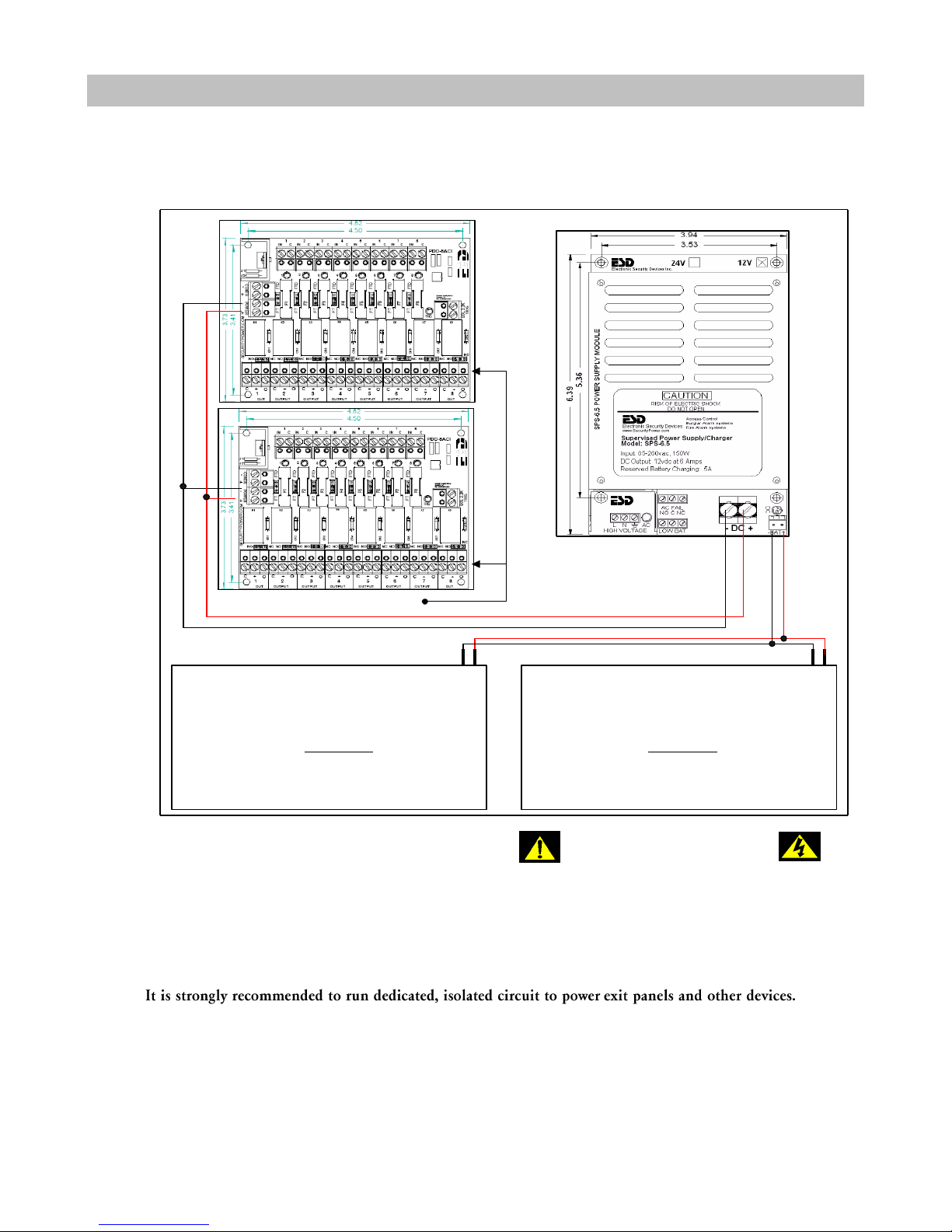
Power Supply for Exit Panel
8 FUSED OUTPUTS
12VDC 8AMP POWER SUPPLY
INPUT AC
VOLTAGE
BATTERY
CONN.
- +- +
12VDC BATTERY
BATTERIES MUST BE WIRED IN
PARALLEL
REFER TO THE MANUFACTURER'S
INSTALLATION MANUAL BEFORE
INSTALLING POWER SUPPLY
Risk of shock
Dry location use only
For indoor use only
Power wire is UL requirement. Failure to use this wire removes UL Listing.
Power Wire 14/2 Stranded shielded Plenum wire.
12VDC BATTERY
BATTERIES MUST BE WIRED IN
PARALLEL

Doc No.: A05160691 REV Q ECO 12425 Date: 03/27/17
NOTE: All life safety and electrical codes must be strictly followed.
1. Seek prior approval from the local life/fire safety officials before installing the SMT Advantage 500DE locking system.
2. Identify all equipment to be installed and inspect for any damage that may have resulted during shipment. If damage is
found notify the carrier immediately and arrange for inspection. Be sure to retain all packing material.
3. Run all Nurse Station and fire alarm cables.
4. Determine the location of the SMT Advantage 500DE Exit Panel and cut holes in the wallboard as needed. Mount surface
mount boxes if required. The SMT Advantage 500DE Exit Panel should be mounted 48 inches from the center of
the panel to the floor.
5. Mount the electromagnetic lock in strict accordance with the manufacturer instructions.
6. Mount the magnetic door contacts on the swing edge of the door.
7. Route all wires into the SMT Advantage 500DE Exit Panel box. (Door contact, Nurse Station, Exit Panel power,
Magnetic Lock, etc...)
8. Prepare all wires for connection to the SMT Advantage 500DE Exit Panel.
9. Determine the location for the Nurse Station and cut hole in wallboard or mount surface mount box as needed.
10.Route Nurse Station cables into the mounting box and prepare wire for connection to the Nurse Station.
11.Make all wiring connections as shown on the following pages.
12.Plug in all power supplies and batteries on the SMT Advantage 500DE Exit Panel as well as the Nurse Station.
13.The system is now ready for testing.
14.Once all connections have been made and the equipment tested for proper operation, the facility’s fire alarm service
company makes the connection to the fire alarm control panel.
NOTE: Up to eight SMT Advantage 500DE Exit Panels can be interfaced to a single relay in
the fire alarm control panel. See the fire alarm connection section of the
manual for more details.
15.Test the fire alarm interface connection by placing the fire alarm system into an alarm mode. All locks should
immediately release.
16.The system should now be operational and your local distributor should provide in-service training.
SECTION4 TYPICAL INSTALLATION

Doc No.: A05160691 REV Q ECO 12425 Date: 03/27/17
This product meets UL 294 Standards
SMT Advantage 500DE Exit Panel
Input Power: 12VDC, 150mA
Magnetic Locks
Input Power: 12VDC, 500mA
4 Channel Monitoring Station
Input Power: 12VDC, 150mA
8 Channel Monitoring Station
Input Power: 12VDC, 300mA
Wire specifications:
Plenum Shielded Fire Wire: 1 pair 16 AWG, part number B60000438
Plenum Shielded Nurse Station Wire: 1 pair 22 AWG, part number B60000429
Plenum Shielded Lock Wire: 3 pair 22 AWG, part number B60000440
Plenum Shielded Power Wire: 1 pair 14 AWG, part number B60018473
NOTE: The magnetic lock is connected to the normally open side of the relay and
closes upon activation. Lock relays are activated by the presence of a valid
transmitter. Lock relays will remain in a locked state while a valid transmitter is
within the detection area of the SMT Advantage 500 DE system.
Nurse/Elevator Relay (1) DPDT Form C: 30VDC, 1A max.
NOTE: The Nurse and Elevator relays are activated when the SMT Advantage
500DE Exit Panel is in an alarm state. The Nurse/Elevator relay will remain active
until the SMT Advantage 500DE Exit Panel is reset.
Mounting Boxes for Exit Panels: Flush Mount Box SCP Part #A10000210
Surface Mount Box SCP Part #401
Dimensions: 4-1/2" (H) x 6-3/8" (W)
2 hour fire rated back boxes available upon request
CAUTION: Use only the DC power supply provided with these units.
Use of a different DC power supply may increase the risk of
fire or electric shock.
SECTION5 SPECIFICATIONS
Doc No.: A05160691 REV Q ECO 12425 Date: 03/27/17
1 32
4 65
7 98
0#
*
Advantage 500 DE
. . . . . . . . . . .. . . . . . . . . . .
Secure Care Products, Inc.
Made With Pride In The U.S.A
Disarmed
Armed
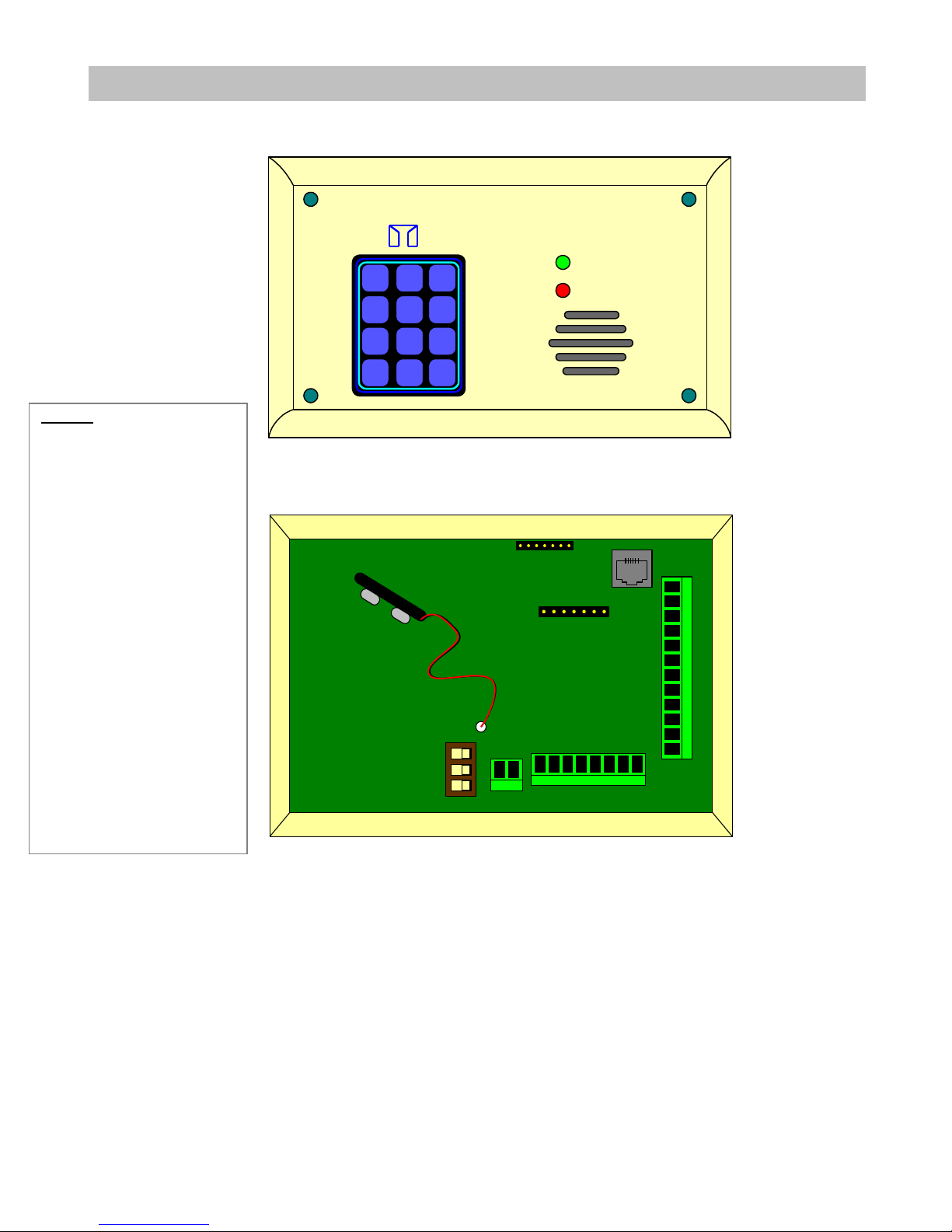
Figure 6-1 Exit Panel, Front View
12 VDC
- + EGRESS DOOR PUSH FIRE
PROGRAMMING
PORT
RECHARGEABLE 9V NI-MH
BATTERY ONLY
EXTERNAL KEYPAD
ON / OFF
MUTE
HI / LO
ELEV NURSE LOCK LOCK
NO C NC NO C NC NO C NC
NO C NC
11
1 2 3 4 5 6
7
8
9
10
Figure 6-2 Exit Panel, Rear View
SECTION6 SYSTEM COMPONENTS
LEGEND
1. Dip Switch’s
On/off
Mute
Hi/low
2. 12-15VDC power input
3. Electromagnetic lock
Delayed Egress connection.
4. Normally Closed door
contact connection
5. Momentary Push Button or
Non-latching Key Switch
6. Fire alarm Normally Open
dry alarm relay connection
(field selectable)
7. Elevator relay
8. Nurse Station relay
9. Electromagnetic lock
relays, one and two
connections
10. Remote Keypad
connection (seven pin)
11. Card Access Input Mode
See Appendix C
SECTION 6 SYSTEM COMPONENTS
Doc No.: A05160691 REV Q ECO 12425 Date: 03/27/17 14
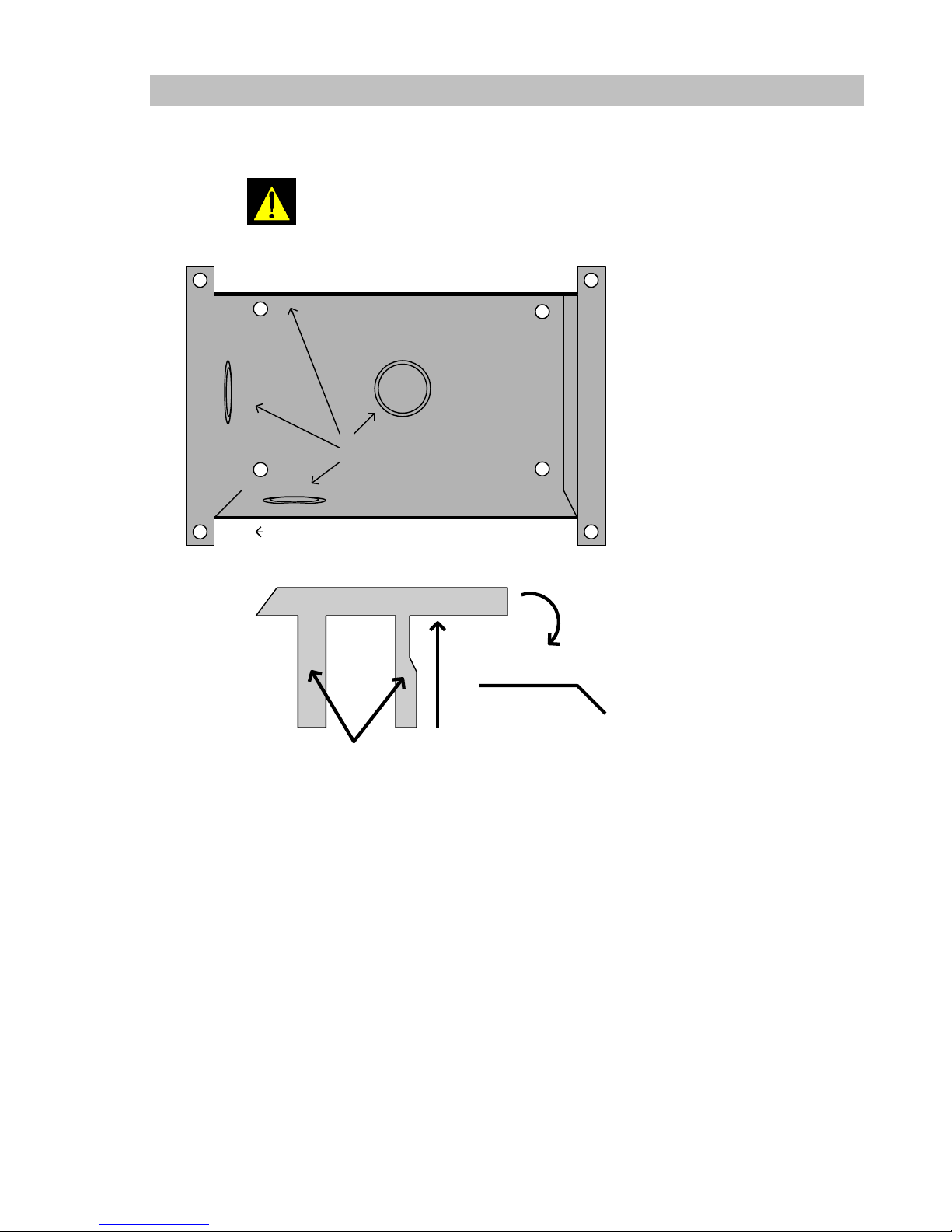
Flush Mount Box
2 hour fire rated back boxes are available upon request
KNOCK OUTS
MADISON CLIP
BEND FLAP DOWN THEN INSERT THE MADISON CLIP
BETWEEN THE BOX AND SHEETROCK SLIDING THE CLIP ALL
THE WAY TO THE END IN THIS CASE TO THE LEFT. THEN FOLD
THE TWO FINGERS UP INTO THE BOX. DO THE SAME TO
ANOTHER MADISON CLIP FOR THE TOP OF THE BOX SLIDING
THE CLIP TO THE OPPOSITE SIDE OF THE FIRST CLIP.
FINGERS
VIEW WITH FLAP FOLDED
Figure 6-3 Flush Mount Back Box

SECTION 6 SYSTEM COMPONENTS
Doc No.: A05160691 REV Q ECO 12425 Date: 03/27/17 15
Surface Mount Box
SURFACE MOUNT BOX
Figure 6-4 Surface Mount Box

Doc No.: A05160691 REV Q ECO 12425 Date: 03/27/17
Standard Operation
The SMT Advantage 500DE Exit Panel is normally armed. To exit through the protected door, enter a valid escort code into
the keypad and open the door. Any time the door is opened without entering a valid escort code into the keypad, the alarm
will sound. When the A41010900 electromagnetic lock is used, the door is normally locked restricting access to authorized
staff members.
PM Mode of Operation
The SMT Advantage 500DE Exit Panel can be programmed to unlock or disarm during certain hours of the day, it then will
automatically lock and unlock at the specified times. These specific times are programmed into the panel by following the
PM programming instructions provided in this Manual. (See Section 10.)
Delayed Egress Timing Control
When used with the A41010900 electromagnetic lock, the SMT Advantage 500DE Exit Panel controls the delayed egress
function of the system. Per Life Safety Code 101, this feature must be used any time the SMT Advantage 500DE System is
used with the A41010900 electromagnetic lock on any door which is designated as an emergency exit door. Delayed Egress
timing is selectable for 15 or 30 seconds.
NOTE: Local officials must approve, in writing, 30-second egress timing prior to use.
Anti-tailgate
This feature re-arms the door automatically after an authorized staff member has passed through the door and it closes. This
prevents unauthorized people from waiting until the staff member passes through the door and exiting without creating an
alarm condition.
SECTION7 STANDARD FEATURES

Doc No.: A05160691 REV Q ECO 12425 Date: 03/27/17
Single Door Contact Connection
Double Door Contact Connection.
Finish the connection to the 500DE
as shown for a single contact at left
Wire Splice
12 VDC
- + EGRESS DOOR PUSH FIRE
PROGRAMMING
PORT
RECHARGEABLE 9V NI-MH
BATTERY ONLY
EXTERNAL KEYPAD
ON / OFF
MUTE
HI / LO
ELEV NURSE LOCK LOCK
NO C NC NO C NC NO C NC
NO C NC
Single or Double Magnetic Door Contact Connections
NOTE: Install the magnetic contacts approximately 1/4 inch (6mm)
apart. The magnetic contacts should not touch when the door is closed.
NOTE: When connecting a double 2 set of magnetic door contacts, splice the door magnetic
contacts in series as show at the right below.
Figure 8- 4 One or TwoSets of Magnetic Door ContactsConnections
Normally Open Push Button (P/N A04150900) Connections
NOTE: The use of release devices which provide a maintained closure are not
recommended for use with SMT Advantage 500DE System.
Figure 8-1 Push Button Connections
SECTION8 INSTALLATION AND CONNECTIONS
Normally open Push-Button
or any other device that
provides a "momentary"
dry contact closure when
activated.
Part #427 Cable
12 VD C
- + EG R E S S D O OR PU S H FIR E
P RO G RA M M IN G
PO RT
RE C HAR GE A B LE 9V N I-M H
BATTE RY O N LY
EX T ERN AL KE Y PAD
ON / OF F
MU T E
HI / L O
ELE V NU R SE LO CK LOC K
NO C N C
NO C N C NO C N C
NO C N C
SECTION 8 INSTALLATION AND CONNECTIONS
Doc No.: A05160691 REV Q ECO 12425 Date: 03/27/17 18
Use SCP Part #B60000429 wire to connect the Push Button to the SMT Advantage 500DE Exit Panel. When the Push Button
is activated the escort delay feature is activated and the door will become disarmed for the programmed exit delay. (See
programming section of this Manual (Section 10) for setting and/or changing the escort delay time.)
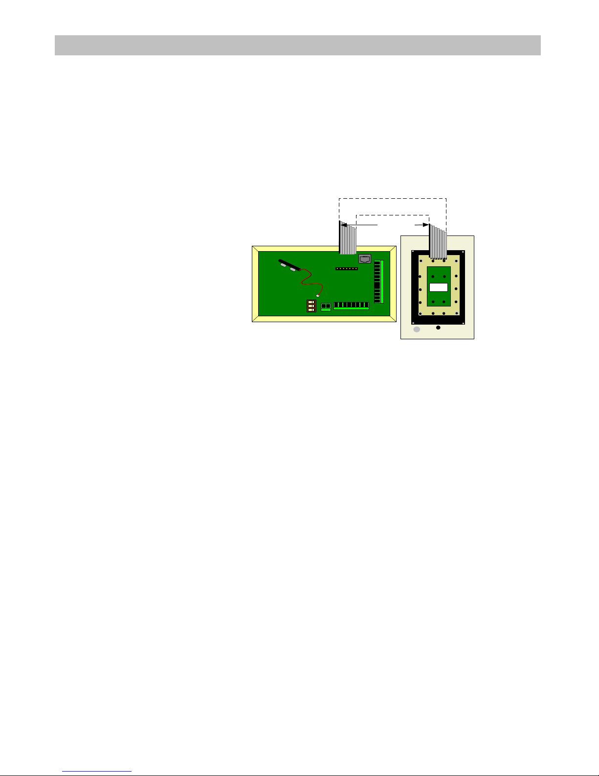
Remote Keypad Connections
When connecting the Remote Keypad connect the ribbon cable as shown below in Fig. 9-5. Figure 9-5 is intended as a
reference to show that no matter the orientation of the SMT Advantage 500DE Exit Panel with respect to the Remote Keypad,
the connections at each end of the ribbon cable should match as shown.
Figure 8-2 Remote Keypad Connections
Available Ribbon Cables
Part # A05032031 = 2 feet
Part # A05032032 = 10 feet
Part # A05032033 = 15 feet
Part # A05032034 = 30 feet
REMOTE
KEYPAD PART #
A05030900
DK
CONNECT THE
RIBBON CABLE SO
THE PINS ARE
CONNECTED AS
SHOWN
RIBBON CABLE
REFERENCE
STRIPE
REAR VIEW
12 VDC
- + EG R E S S D O O R P U S H F IRE
P RO G R AM M I NG
PO R T
REC H ARG E AB LE 9V NI-M H
BATTER Y O NLY
EXT E RNAL KE Y PAD
ON / O FF
MUTE
HI / LO
ELEV N U RSE LOC K L O CK
NO C N C
NO C N C NO C N C
NO C N C
SECTION 8 INSTALLATION AND CONNECTIONS
Doc No.: A05160691 REV Q ECO 12425 Date: 03/27/17 19
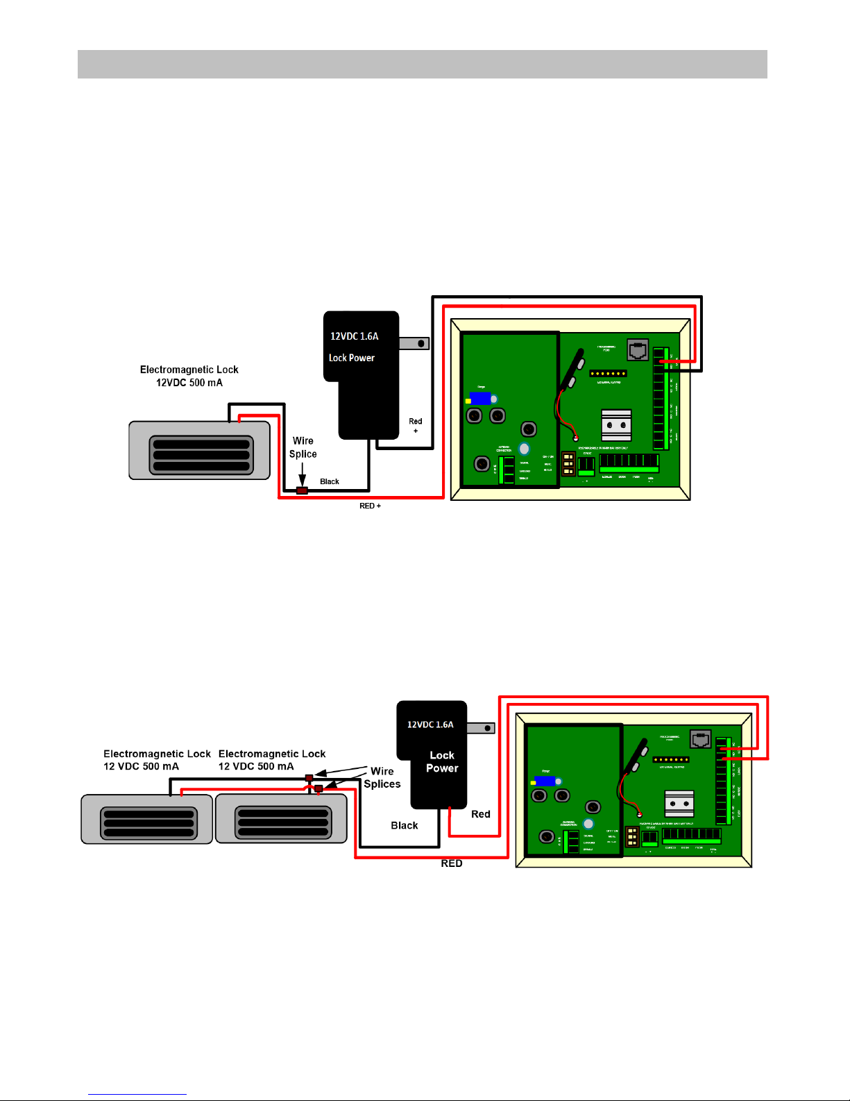
Electromagnetic Lock Connections
Connecting a single electromagnetic lock to the SMT Advantage 500DE Exit Panel
Refer to the manufacturer’s instructions provided with the lock for proper mounting of the lock. Refer to Fig. 9-6 below for
connection to the SMT Advantage 500DE Exit Panel. Use the SCP part #B60000440 22AWG, six-conductor wire for
connections.
NOTE: All applicable electrical and life safety codes must be strictly adhered to when installing
the system.
Figure 8-3 Lock Connections
NOTE: When using electromagnetic locks, the system must be interfaced to the building’s fire
alarm control system. A normally open dry contact relay is required in the fire alarm control
panel for connection to the SMT Advantage 500DE System. Up to eight SMT Advantage
500DE Exit Panels can be interfaced to this relay. If your application includes more than eight
units then multiple relays are required. (See Fire Alarm Connections in this section of the
Manual for more details.)
Figure 8-4 Electromagnetic Lock Connections
Connecting multiple electromagnetic locks to the SMT Advantage 500DE Exit Panel
Refer to the manufacturer’s instructions provided with the lock for proper mounting of the lock. Refer to Fig. 9-7 for
connection to the SMT Advantage 500DE Exit Panel. Use the SCP part #B60000440 22AWG, six-conductor wire for
connections.
SECTION 8 INSTALLATION AND CONNECTIONS
Doc No.: A05160691 REV Q ECO 12425 Date: 03/27/17 20
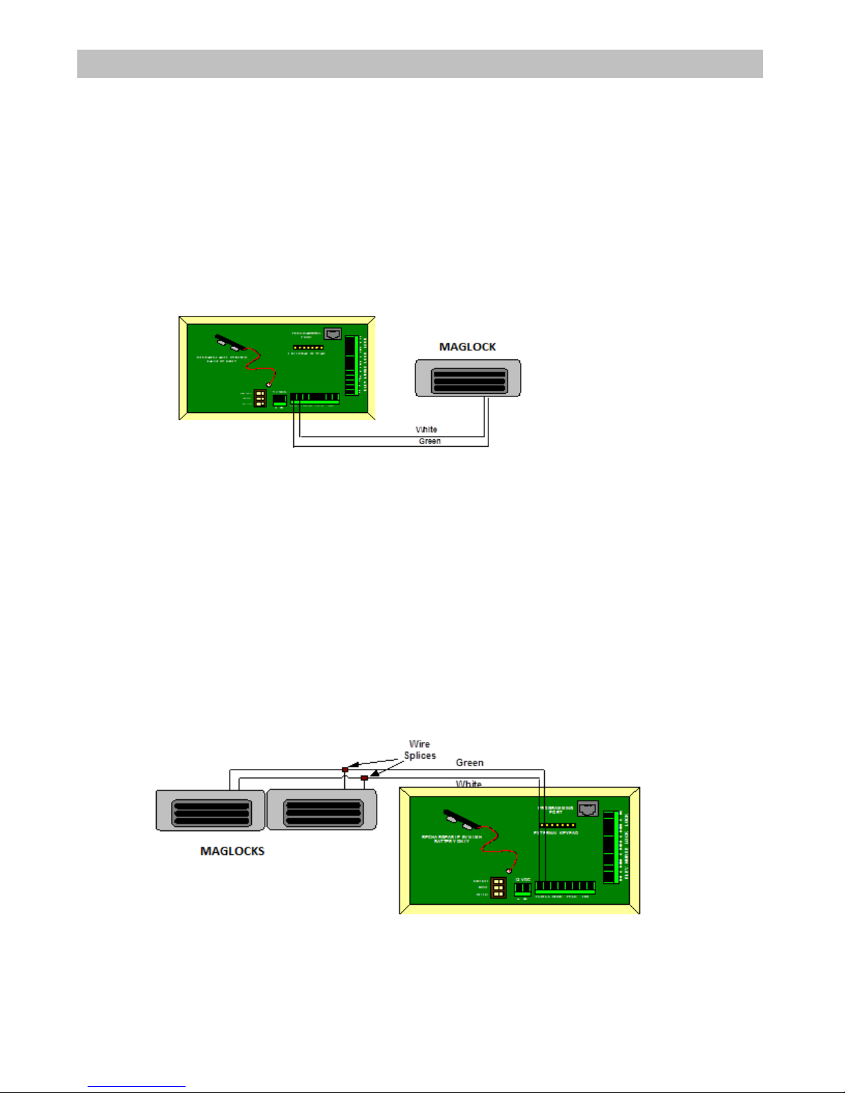
Delayed Egress Switch Connections
Connecting the Delayed Egress Switch to the SMT Advantage 500DE System
Refer to the manufacturer’s instructions provided with the lock for proper mounting of the lock. Refer to Fig. 9-8 for
connections to the SMT Advantage 500DE Exit Panel. Use the SCP part #B60000440 22AWG, six-conductor wire for
connections. All applicable electrical and life safety codes must be strictly adhered to when installing the systems. Refer to
manufacturer’s instructions for details of proper delayed egress operation. (See Section 10 of this Manual for delayed egress
programming details.)
Figure 8-5 Egress Switch Connections
NOTE: Delayed egress switches are wired in parallel.
Connecting multiple Delayed Egress switches to the SMT Advantage 500DE Exit Panel
Refer to the manufacturer’s instructions provided with the lock for proper mounting of the lock. Refer to Fig. 9-9 for
connection to the SMT Advantage 500DE Exit Panel. Use the SCP part #B60000440 22AWG, six-conductor wire for
connections. All applicable electrical and life safety codes must be strictly adhered to when installing the systems. Refer to
manufacturer’s instructions for details of proper delayed egress operation. (See Section 10 of this Manual for delayed egress
programming details.)
Figure 8-6 Two Egress Switch Connections
Other manuals for Advantage 500DE
1
Table of contents
Other Secure Care Security System manuals


Popular Security System manuals by other brands

ADEMCO
ADEMCO VISTA-128B Installation and setup gude

Assa Abloy
Assa Abloy Yale HSA6610 Installation, Programming, Operating Manual

Kerbl
Kerbl 322080 user guide

Hoyles
Hoyles EXITGUARD EX125i quick start guide

Conrad Electronic
Conrad Electronic Renkforce 752181 operating instructions

Unitron
Unitron SMART ALERT Installation & user guide


