Secure Care KinderGUARD ID User manual

Doc. No.: A05280692 Rev.:AE ECO: 13200 Date: 11/04/2019
Installation Manual
KinderGUARD®ID
KinderGUARD®SC-40 ID
With STAT®
39 Chenell Drive
Concord, NH USA 03301-8501
Phone: (800) 451-7917/ (603) 223-0745
Fax: (603) 227-0200
http://www.securecare.com
© 2006 Secure Care Products®, LLC
CONTENT IS SUBJECT TO CHANGE WITHOUT NOTICE
FOR THE LATEST UPDATED MANUALS PLEASE VISIT AND LOG INTO THE DISTRIBUTOR PORTAL AT
WWW.SECURECARE.COM
Please contact your
Distributor /
Installer for service …
Tel.: ___________________________

Doc. No.: A05280692 Rev. AE ECO: 13200 Date: 11/04/2019
2
Table of Contents
SECTION 1 IMPORTANT NOTICES 7
PLEASE READ THIS MANUAL BEFORE BEGINNING THE INSTALLATION OF A SECURE CARE
SYSTEM 7
SECTION 2 SYSTEM BLOCK DIAGRAM 11
SECTION 3 POWER AND GROUNDING REQUIREMENTS 12
SECTION 4 TYPICAL INSTALLATION 13
SECTION 5 SPECIFICATIONS 14
Device Electrical Specifications 14
Wire Specifications 14
Environmental Specifications 14
SECTION 6 COMMUNICATIONS SYSTEM DIAGRAM 15
SECTION 7 STANDARD FEATURES 16
Primary Reset (Escort) Code 16
Tertiary Reset (Escort) Code 16
Secondary Reset (Programming) Code 16
PM Mode 16
Loiter Alarm 16
Delayed Egress Selectable Timing 16
Latching Delayed Egress 17
Software Verification 17
SECTION 8 SYSTEM COMPONENT DESCRIPTIONS 18
KinderGUARD® ID Exit Panel 18
XIU Panel 20
Cutband Receiver 21

Doc. No.: A05280692 Rev. AE ECO: 13200 Date: 11/04/2019
3
SECTION 9 INSTALLATION AND CONNECTIONS 22
Indoor/Outdoor Remote Keypad Layout 22
The Indoor/Outdoor (N/O) Push Button Layout 22
Basic Installation of Mounting Enclosures 23
Remote Annunciation 25
Power Supply for Exit Panel 26
Data Loop for ID Exit Panel to ID Exit Panel 27
ID Exit Panel to XIU Connections 28
ID Exit Panel to External Receiver Connections 29
Second External Receiver Connections 30
Interfacing the Magnetic Locks to the ID Exit Panel 31
Interfacing the Magnetic Solution Locks to the ID Exit Panel 32
Interfacing Two Magnetic Solutions Locks 34
Interfacing the Push Button and the Remote Keypad 35
Delayed Egress and Fire Alarm Connections 36
XIU to Secure Care Software Connections 37
XIU to XIU Connections 38
Single XIU Connection 40
Cutband Receivers Data Loop 41
Power Supply for the Cutband Receivers 42
Cutband Receiver Data Connection 43
Setting the Proper Cutband Receiver ID Code 44
Mounting the Cutband Receiver 50
Programming the STAT ID Exit Panel 51
SECTION 10 PROGRAMMING INSTRUCTIONS 51
Reset Escort Codes 51
Escort Time 52
Delayed Egress Release Time 52

Doc. No.: A05280692 Rev. AE ECO: 13200 Date: 11/04/2019
4
Delayed Egress Activation Time 53
Latching Delayed Egress 54
Irreversible Latching Delayed Egress 54
No Code/ Irreversible Delayed Egress 55
Fire Alarm Input Selection 55
Enable/Disable the Signal LED 55
Latching Fire Alarm 56
Locking of Life Safety 101 Features 56
Software Version 56
Elevator Mode 56
Loiter Alarm 57
Advanced Security Mode 57
Antenna Selection 58
Antenna Range Adjustment 58
Testing the CAN Bus 58
Date Time Change 59
PM Mode Feature 59
Setting Exit Panel ID Code 60
Escort Pendant Enable/Disable 60
Defaulting The STAT ID Panel 60
XIU Programming 61
SECTION 11 TESTING KINDERGUARD ®ID SYSTEM WITH LOCK 63
Recommended Weekly Testing 63
Patient Escort and Anti-Tailgate Feature Test 63
Delayed Egress Feature Test 63
Remote Keypad Test 63
Push Button Test 63
Advanced Security Mode Test 63
Recommended Monthly Testing 63
Fire Alarm Release Feature Test 63
Recommended Annual Service 63
Battery Replacement 63

Doc. No.: A05280692 Rev. AE ECO: 13200 Date: 11/04/2019
5
Using a Transmitter/System Tester 64
SECTION 12 TROUBLESHOOTING 65
SECTION 13 GENERAL PRODUCT WARRANTY 69
1. Notices 69
2. Limited Warranty 71
3. Limitations of Liability 72
4. Governing Law and Arbitration 72
5. Severability 73
6. Waiver 73
SECTION 14 COMPLIANCE INFORMATION 73
APPENDIX A UL LISTING REQUIREMENTS 82
APPENDIX B FERRITE PLACEMENT 83
Recommended Ferrite Placement 83
Correct and Incorrect Ferrite Installation 84
APPENDIX C 983 EXT. RECEIVER KIT 85
Cutband Receiver Layout 86
APPENDIX D OLD CUTBAND RECEIVER LAYOUT AND DIPSWITCH SETTINGS 86
Cutband Receiver to XIU Connections 87
Setting the Proper Cutband Receiver ID Code 88
APPENDIX E OLD PM PROGRAMMING 93
PM Mode Feature 93
Display PM Times 93
APPENDIX F 4 AMP POWER SUPPLY FOR EXIT PANELS 94
APPENDIX G 4 AMP POWER SUPPLY FOR CUTBANDS 95
Power Supply Connections for the Cutband Receiver 95

Doc. No.: A05280692 Rev. AE ECO: 13200 Date: 11/04/2019
6
APPENDIX H CALIFORNIA FIRE MARSHALL LISTING 96
Table of Figures
FIGURE 2-1 SYSTEM BLOCK DIAGRAM 11
FIGURE 8-1 REAR VIEW OF ID EXIT PANEL 18
FIGURE 8-2 FRONT VIEW OF KINDERGUARD ID EXIT PANEL 19
FIGURE 8-3 REAR VIEW OF XIU PANEL 20
FIGURE 8-4 CUTBAND RECEIVER LAYOUT 21
FIGURE 8-5 REAR VIEW OF REMOTE KEYPAD 22
FIGURE 8-6 REAR VIEW OF PUSH BUTTON 22
FIGURE 9-1 SURFACE MOUNT ENCLOSURE 23
FIGURE 9-2 FLUSH MOUNT ENCLOSURE 24
FIGURE 9-3 POWER SUPPLY CONNECTION 26
FIGURE 9-4 DATA LOOP FOR ID EXIT PANEL TO XIU CONNECTION 27
FIGURE 9-5 ID EXIT PANEL TO XIU CONNECTIONS ERROR! BOOKMARK NOT DEFINED.
FIGURE 9-6 ID EXIT PANEL TO EXTERNAL RECEIVER CONNECTIONS 29
FIGURE 9-7 SECOND EXERNAL RECEIVER CONNECTIONS 30
FIGURE 9-8 MAGNETIC LOCKS TO ID EXIT INTERFACE 31
FIGURE 9-9 ID EXIT PANEL TO MAGNETIC SOLUTIONS LOCK INTERFACE 33
FIGURE 9-10 INTERFACING TWO MAGNETIC SOLUTIONS LOCKS 34
FIGURE 9-11 PUSH BUTTON AND REMOTE KEYPAD INTERFACE 36
FIGURE 9-12 DELAYED EGRESS AND FIRE ALARM CONNECTIONS 37
FIGURE 9-13 XIU TO SECURE CARE SOFTWARE CONNECTIONS 38
FIGURE 9-14 XIU TO XIU CONNECTION 39
FIGURE 9-15 SINGLE XIU CONNECTION 40
FIGURE 9-16 CUTBAND RECEIVERS DATA LOOP 41
FIGURE 9-17 POWER SUPPLY FOR THE CUTBAND RECEIVERS 42
FIGURE 9-18 CUTBAND RECEIVER DATA CONNECTION 43
FIGURE 9-19 MOUNTING THE CUTBAND RECEIVER 50

Doc. No.: A05280692 Rev. AE ECO: 13200 Date: 11/04/2019
7
PLEASE READ THIS MANUAL BEFORE BEGINNING
THE INSTALLATION OF A SECURE CARE SYSTEM
SECTION1 IMPORTANT NOTICES

Doc. No.: A05280692 Rev. AE ECO: 13200 Date: 11/04/2019
8

Doc. No.: A05280692 Rev. AE ECO: 13200 Date: 11/04/2019
9

Doc. No.: A05280692 Rev. AE ECO: 13200 Date: 11/04/2019
10

Doc. No.: A05280692 Rev. AE ECO: 13200 Date: 11/04/2019
11
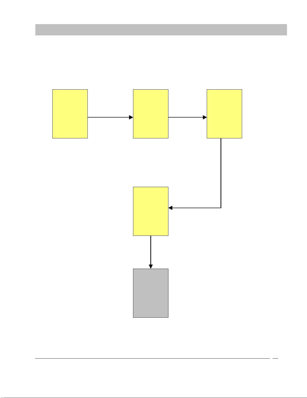
Figure 2-1 SYSTEM BLOCK DIAGRAM
NOTE: This diagram is UL required. Do not remove or change Part Number or Figure #.
SECTION2 SYSTEM BLOCK DIAGRAM

Doc. No.: A05280692 Rev. AE ECO: 13200 Date: 11/04/2019
12
NOTE: Throughout this manual the KinderGUARD® ID and KinderGuard SC- 40 ID Exit Panels
will be referred to as “ID Exit Panel”
Each ID Exit Panel and XIU can be powered by the wall mount local power supply . Cutband Receivers are
powered by an Electronic Security Devices STS-10CEELACI16CL central power supply on a
110/220/230VAC duplex outlet specific to regional or country options.
It is strongly recommended to run dedicated, isolated circuit to power exit panels and other devices.
NOTE: Do not extend the power supply cord provided. The maximum distance the
duplex outlet should be from the ID Exit Panel is ten cable feet.
NOTE: Do not connect to a receptacle controlled by a switch.
PLEASE READ SAFETY PRECAUTIONS IN SECTION 4 BEFORE PROCEEDING
SECTION3 POWER AND GROUNDING REQUIREMENTS

Doc. No.: A05280692 Rev. AE ECO: 13200 Date: 11/04/2019
13
WARNING: All life safety and electrical codes must be strictly followed.
As with any Infant Monitoring System, each application can be different. Use the guidelines below as a basic
understanding of what a standard application would be like.
1. Seek prior approval from local life safety officials prior to installing an ID locking system.
2. Identify all equipment to be installed and inspect for any damage that may have resulted during shipment. If
damage is found notify the carrier immediately and arrange for inspection. Be sure to retain all shipping and
packaging materials.
3. Install all communication wires from each exit system to the system annunciator location (computer location).
Secure Care strongly recommends that all wiring used to install Secure Care equipment be run at least 18 inches
from all other wiring and not be installed inside metal conduit. It is also strongly recommended to not utilize
cable trays used in networking installations and to secure the wires off of ceiling grids. If the wiring is installed
in any of these manners it could cause undesired induction of Radio Frequency (RF) interference with our
system.
4. Determine the location of the exit control panel, making sure to accommodate for any local, stats, or federal
codes or guidelines including ADA (American Disability Act) requirements, and mount as required. Standard
applications would place this equipment on the wall at the center of the door height on the latch side.
5. Mount the electromagnetic lock in strict accordance with the manufacturer installation instructions. Be sure to
comply with all Life Safety and Electrical Codes as required.
6. Mount the magnetic door contacts provided with the Exit Kit on the latch side of the door. These contacts provide
a method of monitoring the open or closed status of the door.
7. Route all necessary peripheral connection wires into the exit control panel mounting box. These would include
wires such as communication, magnetic contacts, exit power, magnetic lock power, etc.
8. Prepare all wires and make connections to the exit system. Special care should be taken to prevent loose
connections and shorts.
9. Proceed to the remote system annunciator location to mount as required. This device should be easily visible to
staff for monitoring of the system. Common locations are centralized nurse stations or staffed reception areas. .
10. Make all necessary wiring connections as shown in Section 9 of this manual.
11. Plug in all power supplies and batteries. Do not connect to a switched receptacle.
12. The system is now ready for tuning, programming, and testing.
13. When using the STAT Cutband feature for an Adult application please visit and log into the Distributor portal
@ WWW.SECURECARE.COM and refer to Technical Bulletin # 24
SECTION4 TYPICAL INSTALLATION

Doc. No.: A05280692 Rev. AE ECO: 13200 Date: 11/04/2019
14
This product meets UL 294 Standards
Device Electrical Specifications
XIU, Door GUARDIAN and KinderGUARD Exit Panels
Input Power: 12 - 15VDC
Relay Specifications: Max. 30VDC (only) 1 Amp
Battery Back Up: Rechargeable 9VDC Ni-MH battery
Battery Back Up Time: Approximately 30-40 minutes
Max Current Draw: 150 mA
Magnetic Lock
Input Power: 12VDC
Battery Back Up: None
Max Current Draw: 500 mA
Ext. Receiver
Input Power: 12VDC
Battery Back Up: None
Max Current Draw: 25 mA
Wire Specifications
Plenum Shielded Fire Wire: 1 pair 16 AWG, PN B60000438
Plenum Shielded Communication Wire: 1 pair 22 AWG, PN B60000429 for 250FT and B60001429 for
500FT.
Plenum Shielded Ext. Receiver Wire: 1 pair 22 AWG, PN B60000429 for 250FT and B60001429 for
500FT.
Plenum Shielded Lock Wire: 3 pair 22 AWG, PN B60000440 for 250FT and B60001440 for
500FT.
Plenum Shielded Power Wire: 1 pair 14 AWG, PN B60018473
Remote Keypad Cable 2 Foot Cable A05032031
10 Foot Cable A05032032
15 Foot Cable A05032033
30 Foot Cable A05032034
Environmental Specifications
SAFETY
Please pay attention to the following safety warnings: These products should not be used in a manner
not specified by the manufacturer.
Operating temperature 5°C to 40°C
Storage temperature -10° to + 50°
Refer servicing to trained, qualified personnel
There are no serviceable parts inside the Ext. Receiver.
Do not operate the device in the presence of flammable gases or fumes. Operation of any
electrical instrument in such an environment constitutes a definite fire hazard.
Do not install substitute parts or perform any unauthorized modifications to the instrument.
Power supply: Risk of shock
Dry location use only
For indoor use only
2 hour flame rated back boxes available upon request.
SECTION5 SPECIFICATIONS
Doc. No.: A05280692 Rev. AE ECO: 13200 Date: 11/04/2019
15
See figures in Section 9 for detailed connections.
ID Exit Panel ID Exit Panel ID Exit Panel
XIU
Secure Care
Software
Jumper ON Jumper OFF
Jumper OFF
Jumper ON
Up to 95 total ID Exit Panels per XIU for CAN (Control Area Network) communications
A01350904
Custom Made SCP
Cable
PC
Figure 6-1 System Layout ID Exit Panels and XIU to Secure Care Software
NOTE: For the central power supply connections please refer to Figure 9-4 in Section 9 of this manual
SECTION6 COMMUNICATIONS SYSTEM DIAGRAM

Doc. No.: A05280692 Rev. AE ECO: 13200 Date: 11/04/2019
16
The perimeter of an installed collection of ID Exit Panels creates a selective monitoring system. This system is designed
to augment your policy regarding personal security of infants and small children. If used and tested properly, the system
should provide many years of trouble free operation. The standard system consists of the ID Exit Panel, the
Electromagnetic Lock, theReceiver/Antenna,Magnetic Door Contacts,andanactiveTransmitter.
ThestandardmodeofoperationfortheExitSystemallowsfreeaccessofthedoorbystaffmembersandvisitorsbutquietlylocksthedoor
when an infant wearing a monitored transmitter approaches the door. When the infant leaves the monitored area, the door unlocks and
access is again available for staff and visitors. If a staff member is required to escort an infant wearing a monitored transmitter out of the
protectedarea,an escort code canbeentered into theIDExitPanel keypad toallowboththe staffmemberand theinfant to pass through
theperimeterwithoutcausinganalarm.
Other key features are described in basic detail below and can be activated at the time of installation or at any time after by a trained
technician.
Primary Reset (Escort) Code
This code is used to reset an alarm condition or escort an individual wearing a monitored transmitter through a door
without creating an alarm condition. In the Advanced Security Mode, the primary reset (escort) code will not allow access
through a monitored door location. Only staff members should be allowed to reset an alarm condition or escort a
monitored resident / infant out of the building without creating an alarm. This code should not be given to family
members or visitors.
Tertiary Reset (Escort) Code
This code is used to reset an alarm condition or escort an individual wearing a monitored transmitter through a door
without creating an alarm condition. In the Advanced Security Mode, the tertiary reset (escort) code will not allow access
through a monitored door location. Only staff members should be allowed to reset an alarm condition or escort a
monitored resident / infant out of the building without creating an alarm. This code should not be given to family
members or visitors.
Secondary Reset (Programming) Code
In the Advanced Security Mode, the secondary code is used to escort a monitored resident/infant through a monitored
door. This code is also used to enter the programming mode of the system. This code should not be given to family
members or visitors.
PM Mode
This feature allows the ID Exit Panel to be programmed to lock and unlock the door automatically at certain times of the
day whether a monitored transmitter is near the detection zone or not. Usually used at night, this feature will provide an
extra high level of security when staff levels are lowest.
Loiter Alarm
When enabled, this feature will create an alarm condition whenever a monitored transmitter remains within the detection
range of an exit for a predetermined period of time.
Delayed Egress Selectable Timing
This feature allows the ID Exit Panel to be programmed for either a 15 or 30 second release upon activation of the delayed
egress function. Per NFPA Life Safety Code 101, release time must be pre-approved by local life safety officials prior to
being activated.
SECTION7 STANDARD FEATURES

Doc. No.: A05280692 Rev. AE ECO: 13200 Date: 11/04/2019
17
Latching Delayed Egress
Enabling the latching delayed egress function of the ID Exit Panel allows the electromagnetic lock to remain unlocked
whenever the delayed egress cycle has released the door and a monitored resident/infant has exited the perimeter. A valid
reset (escort) code entered by an authorized staff member is required before the door can be locked again.
Software Verification
The software verification feature allows the user to determine which software version is installed in the ID Exit Panel.
The ID Exit Panel LED’s will blink and the sounder located on the front of the ID Exit Panel will chirp in specific
sequences that are to be counted for identification. The ID System is interfaced to the facility elevator system.
SECTION 7 STANDARD FEATURES

Doc. No.: A05280692 Rev. AE ECO: 13200 Date: 11/04/2019
18
KinderGUARD® ID Exit Panel
NOTE: Not all ID Exit Panels will have every feature set or all components
populated. Refer to specific Part Number or Exit Panel model name for
available feature sets.
The ID Exit Panel is a microprocessor-based unit that recognizes pulse signals sent from Secure Care Products, Inc.
Transmitters. This perimeter control panel can allow for traffic to pass normally, but can engage an optional magnetic
lock when a Secure Care transmitter is within detection range. The ID Exit Panel should create an audible and visual
alarm when a transmitter is in detection range and the door is open. The system can trigger an alarm at a PC based Secure
Care Software graphic annunciator in a specified remote location. The escort feature allows infants wearing Secure Care
Products, Inc. Transmitters to be escorted without alarm when an authorized, user programmable, four digit code is
entered. The anti-tailgate feature should immediately re-arm the system when the door has closed to prevent an
unauthorized exit. The PM feature allows the system to lock or alarm for exit/entry during specified time periods.
Figure 8-1 Rear View of ID Exit Panel
SECTION8 SYSTEM COMPONENT DESCRIPTIONS
FIRE PUSH DOOR EGRESS
LOCK AUX
CAN
L
CANH
GND
SECURE CARE PRODUCTS
AUX
LOCK
- +
NO C NC NO C NC NO C NC NO C NC - +
KEYPAD
O N
1 2 3 4
1 2 3 4 5 6 7
1 2 3 4
2 3 41 6
7
8
9
5
11
10
12
1- Power
2- Mute
3-Loud/Soft
4- Not Used
LEGEND
1. Electromagnetic lock Delayed Egress
connection
2. Normally Closed door contact
connection
3. Momentary Push Button or Non-
latching Key Switch
4. Fire alarm Normally Open dry alarm
relay connection (field selectable)
5. Controlled area network (CAN)
connection
6. Remote Keypad connection (seven
pin)
7. Electromagnetic lock relays , one and
two connections
8. Auxiliary relays (one and two
connections)
9. 12-15VDC power input connections.
Use plug-in power supply or central
power supply.
- 10. CAN Bus termination jumper
11. Ext. Receiver connections
12. Dipswitch settings
Doc. No.: A05280692 Rev. AE ECO: 13200 Date: 11/04/2019
19
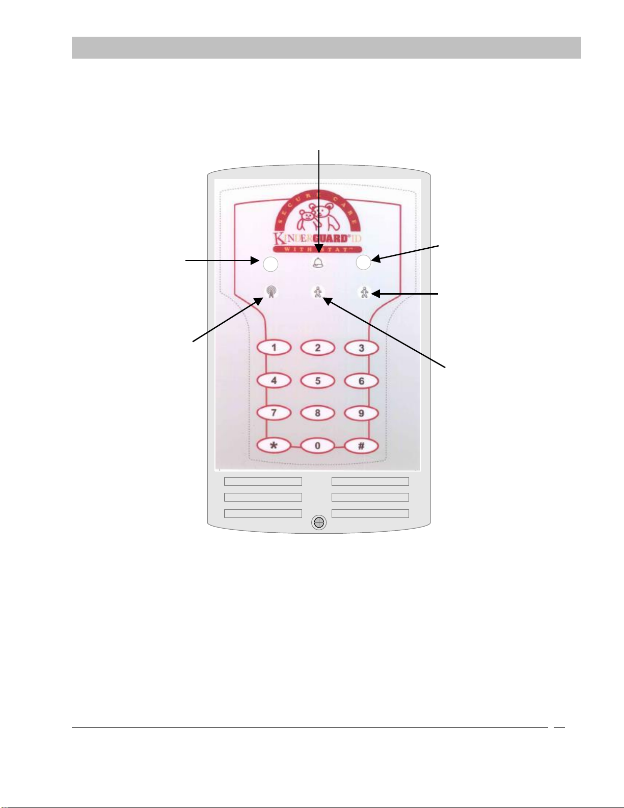
Door is armed
(Red)
LED will turn off when
Escort code is
entered. Flashing Red
Fire is activated
Panel is ON
(Green)
Transmitter is
being
detected
(flashing Yellow)
Door is alarming
(Flashing Red)
Transmitter is within
range of panel (Red)
Keypad punch
indicator(lights when
any key is pressed)
If two transmitters
are present then the
center light is solid
and
If three or more
transmitters are
present then the
center light will blink
Figure 8-2 Front View of KinderGUARD ID Exit Panel
KinderGuard SC-40 ID not depicted
SECTION 8 SYSTEM COMPONENT DESCRIPTIONS

Doc. No.: A05280692 Rev. AE ECO: 13200 Date: 11/04/2019
20
XIU Panel
The XIU communication hub is designed to provide a method of message control for all field installed devices using the
CAN bus architecture for supervision and event message transmission. Up to 95 total exit panelsor 30 Cutband Receivers
may be connected to one XIU unit. Each device will require its own uniquely programmed addressable ID. The XIU
passes the input messages through a PC based Secure Care Software graphical annunciator. . When using more than one
XIU per system all ID Exit Panels will be connected to one XIU, and all the Cutband Receivers will be connected to a
different XIU. Both XIU’s will be interfaced to each other to lock the doors during a cutband alarm via data
communication. The XIU is equipped with two auxiliary relays (Form C relays) which activate during a cutband alarm.
FIRE PUSH DOOR EGRESS
AUX
CA
NL
CANHGND
SECURE CARE
PRODUCTS
LOCK
- +
NO C NC - +
KEYPAD
O
N
1 2 3 4
1 2 3 4 5 6 7
1) POWER
2) NOT USED
3) NOT USED
4) NOT USED
LOCK
NO C NC AUX
NO C NC NO C NC
2
4
5
6
3
1
Figure 8-3 Rear View of XIU Panel
SECTION 8 SYSTEM COMPONENT DESCRIPTIONSSECTION 8 SYSTEM COMPONENT DESCRIPTIONS
LEGEND
1 XIU to XIU Only used with
Cutband system. Refer to
Figures 9-15 and 9-16
2 RS232 connection to a Nurse
Station or SCP Software
3 Controlled Area Network
(CAN)
4 Backup battery holder
5 12-15VDC power input
connection
6 Auxiliary relay connection
(Form C relays)
This manual suits for next models
1
Table of contents
Other Secure Care Security System manuals


Popular Security System manuals by other brands


König
König SAS-ALARM240 user manual

Tiras
Tiras DETECTO BTN100 quick start guide

Panasonic
Panasonic SF4B-H12C instruction manual

Safety Basement
Safety Basement SB-CVR4000 instruction manual

Electronic Devices Limited
Electronic Devices Limited ED816A instruction manual

Barnett Engineering
Barnett Engineering ProTalk Cv3 Replacement instructions


