Securitron MXD-62 User manual

Copyright, 2000, all rights reserved •Securitron Magnalock Corp., 550 Vista Blvd., Sparks NV 89434, USA
Tel: (775) 355-5625 •(800) MAGLOCK •Fax: (775) 355-5636 •Website: www.securitron.com
An ASSA ABLOY Group company
PN# 500-12800 Page 1
Rev. A.2, 6/00
SECURITRON MODEL MXD-32, MXD-62 DOOR MOVEMENT EXIT DELAY
INSTALLATION AND OPERATING INSTRUCTIONS
1. DESCRIPTION
The MXD consists of several components which, when combined with a Magnalock, will
produce an initiate signal for delayed exit as controlled by Securitron’s XDT logic timer when
a person pushes on the door and moves it a modest distance.
The specific components within the MXD “kit” are:
A mounting sub-plate which affixes the magnet body to the door frame or header.
A sealed proximity switch array which is also mounted on the sub-plate. This changes state
to provide the initiate signal.
A stamped, stainless steel housing which covers the magnet body and proximity switch array.
A sealed permanent magnet affixed to a bracket that mounts behind the strike plate. As this
unit moves away from the proximity array, the array switches.
A special sex bolt with internal spring that permits the door to move away from the strike
plate (the strike plate remains secured to the magnet body) so as to create the initiate signal
when a person pushes on the door opening it up to one inch.

Rev. A.2, 6/00 Page- 2
Use of the MXD permits delayed exit without the need to alter the existing door latch and
hardware. The relatively large door movement that it supports (up to one inch) eliminates the
potential problem of false triggering if the door is rattled or subjected to wind loads. It is also
highly tamper resistant in the event that someone would wish to defeat its safety function of
allowing people to exit.
2. PHYSICAL INSTALLATION
2.1 DETERMINING HORIZONTAL OR VERTICAL MOUNT AND APPLYING TEMPLATE
The MXD can be mounted horizontally under the frame header or vertically along the frame.
Once you have selected the orientation for your installation, apply the template to set your
hole drilling positions. To apply the template, close the door (be sure it latches) and note that
the template has a folding line on it. The magnet mounting “sub-plate” is on one side of the line
and the strike plate/permanent magnet bracket is on the other. Position the fold in the template
along the edge the door stop makes with the door surface so that the sub-plate portion of the
template extends on to the door stop and the strike/permanent magnet bracket portion extends
on to the door surface. If you have a swing through type aluminum frame glass door, there
is no door stop so you simply position the template fold line on the edge between the door
surface and frame stile. In planning your installation for this type of door, a special
consideration comes into play. First, before drilling any holes, you want to be sure that the
aluminum door rail is wide enough to support the sex bolt. The MXD sex bolt is 1” (25MM)
diameter which is much thicker than normal magnetic lock sex bolts. This type of door is made
with extrusion widths which vary widely but some are so narrow that you can only mount the
MXD sex bolt when you are using the model 32 lock. Some others will accept a model 62 lock
but only when you are using the offset strike.
To determine in advance whether your door and the Magnalock that you intend to use will
accept the MXD sex bolt, just hold the template so that you can visually see the center point of
where the sex bolt will go into the door rail. Assure yourself that a 1” diameter hole around this
point will not strike the glass or any support rods internally.
Note: if you have an aluminum frame glass door with a blade stop, see the next section as the
template is used differently. Otherwise, the template will work on horizontal or vertical mounts
and on left hand or right hand doors but be sure that the edge of the template is flush to the
corner of the door stop for best mounted appearance (the MXD housing will reach to the corner
of the door stop).
Tape the template into position and using a center punch, mark the hole locations on the door
and frame. The template will indicate the number and positions of the hole locations as well as
the hole diameters. This depends on which Magnalock type is being used. Note that if the door
stop is narrow, you may need to add a filler plate to create a wide enough mounting surface for
the sub-plate.
2.2 TEMPLATE USE ON AN ALUMINUM FRAME GLASS DOOR WITH BLADE STOP
A blade stop is so narrow (around 1/8”) that nothing can be mounted on it. Therefore, you
cannot place the folded edge of the template in the corner made by the stop and door surface
as you will not be mounting on the stop. You will be mounting the sub-plate adjacent to the
stop directly on the frame extrusion. To use the template in this exceptional situation, cut it with
a scissors along the fold line. To mark the strike plate/permanent magnet bracket holes, open
the door slightly and insert the template behind the blade stop until it just touches the door
frame. Then allow the door to fully close (this will capture the template). You can then

Rev. A.2, 6/00 Page- 3
accurately punch your mounting holes for the strike plate/permanent magnet bracket just as if
the blade stop was not present.
To mark the holes for the sub-plate, you will use the other half of the template. Normally, you
would position its fold line edge to rest against the door surface but the blade stop is in the way.
Simply measure the distance from the door surface to the surface of the blade stop and
“subtract” that distance from the template half by either cutting the template or re-folding it. The
distance is usually around 3/8” (9.5MM) but it will vary from door to door depending on the
thickness of the blade stop and the spatial point at which the door is closed.
An alternate method for mounting the sub-plate dispenses with the template half and uses the
sub-plate as its own template. To employ this method, close the door and measure back from
the surface of the door past the blade stop 5/8” (16MM) for a model 32 Lock or 9/16” (14MM)
for a model 62 Lock. The best way to do this is to make two measurements and mark two
points each of which is the correct distance away from the surface of the door. Then a line can
be drawn between the two points. The sub-plate may be used as a straight edge for drawing
this line.
Align the front edge of the sub-plate to this line and you have achieved the correct backset.
To set the lateral position of the sub-plate, move it away from the frame corner about 1/8”
(3MM). This will allow the housing cover to fit over it and still produce an attractive mount that
appears to reach to the frame corner. Then mark and drill the mounting holes for the sub-plate.
2.3 IF THE DOOR IS THINNER OR THICKER THAN STANDARD
The MXD sex bolt is dimensioned to precisely fit a 1 3/4” (44.5 MM) thick door which is a
common size. If the door is a different thickness, contact the factory. Securitron can supply
washers for a thinner door, which go under the head and key in to the anti-rotation pins while
including new anti-rotation pins. For a thicker door, the bolt may be partially unscrewed to
expand it for use with up to a 2” thick (51MM) door. If you do this, be sure to install Threadlock
on the threads (Threadlock is furnished in a capsule with the MXD). When the bolt is
“expanded” to suit a thicker door however, its ability to allow to door to move for delay initiation
is proportionately reduced. The factory, however, can supply spacers to adapt the bolt to thicker
doors while retaining full door movement distance.
2.4 MOUNTING THE PERMANENT MAGNET BRACKET, MXD SEX BOLT AND STRIKE
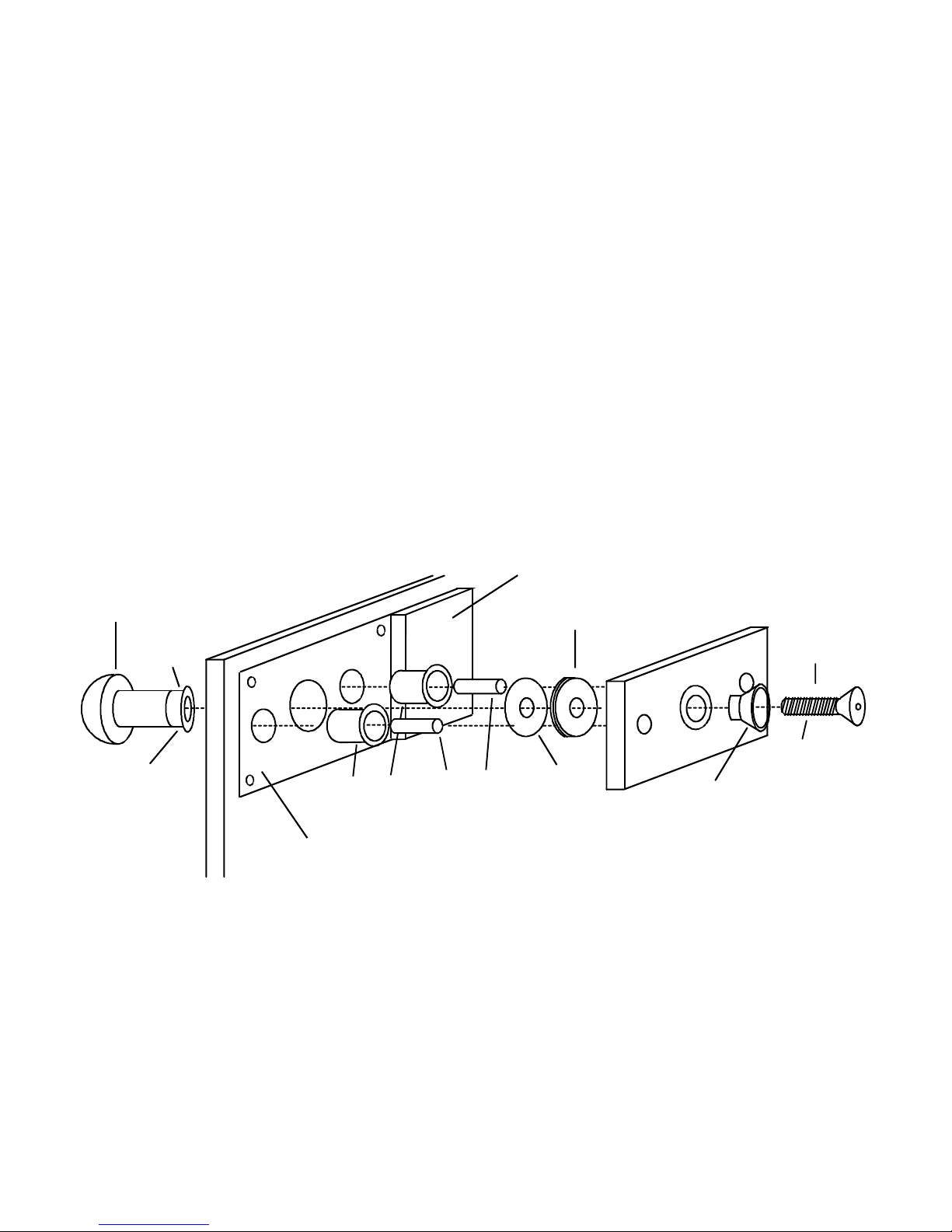
Note the assembly drawing in Figure 1. The first step after all the holes are drilled from the
template is to install the permanent magnet bracket. The model 62 version comes with four
self tapping screws to hold the bracket to the door and the model 32 version comes with two.
Note that this bracket is not handed. It can be flipped to place the permanent magnet
(concealed in an aluminum block) either to the right or the left to line up with the proximity switch
array on the sub-plate. The proximity switch array can also be transferred to either side of
the sub-plate (the holes are drilled for either position). The reason for this flexibility is to
maximize wiring options. In the case of a concrete filled header, for example, the cable can
not usually be pulled up into the header. A flex conduit fitting can be attached to either end of
the cover and the proximity switch array and permanent magnet pack would then be positioned
on the opposite side of the fitting.
Your next task is to mount the special MXD sex bolt. Be sure you have checked the previous
Section which covers a situation that deviates from standard sex bolt installation. Then, note
that the bolt includes two pins under the head which will go in two separately drilled holes for
anti-rotation. The pins act as their own template. Unscrew the threaded base plate of the bolt
and insert the bolt into the 1” hole which you should have previously drilled. Tapping the bolt
head will cause the pins to mark the door. Remove the bolt and drill 3/16” (5MM) diameter
Rev. A.2, 6/00 Page- 4
holes for these anti-rotation pins. Then, reinstall the sex bolt head, install some Threadlock
from the capsule on the sex bolt base plate threads and screw in the base plate
Next, install the roll pin bushings into the holes previously prepared for them and install the long
(2”) roll pins into the strike plate. Do not use the shorter roll pins delivered with the
Magnalock. Then, place the flathead strike mounting screw through its plastic bushing and
through the strike plate. On the other side of the plate, push three rubber washers and one
steel washer onto the strike mounting screw as shown in Figure 1. To screw this complete
assembly into the MXD sexbolt, you have to follow a special procedure to prevent the female
threaded shaft in the MXD sexbolt from spinning. First, apply Threadlock onto the strike
mounting screw threads and then Insert the screw into the MXD sexbolt and turn it a couple of
times to catch a few threads. Then pull on the strike plate so that the spring loaded female
threaded shaft in the sexbolt comes out. Hold it out against its spring pressure by rotating the
strike a bit so that the roll pins no longer go into their bushings but hit the permanent magnet
bracket. This will allow you to get a vise grip onto the female threaded shaft in the MXD sexbolt.
Turn the strike mounting screw a couple of more turns and then re-rotate the strike so that its
roll pins again insert into their bushings. Then finish tightening the strike mounting screw but
don’t over-tighten so that the rubber washers become compressed.
FIG. 1: STRIKE PLATE MOUNTING ASSEMBLY
SEXBOLT
MXD
STRIKE
FLATHEAD
SCREW
ROLL PINS
3 X RUBBER
WASHERS
DOOR
WHITE PLASTIC
BUSHING
WHITE PLASTIC
BUSHINGS
PERMANENT MAGNET
PERMANENT MAGNET
BRACKET NOTE: MXD-62 IS SHOWN. MXD 32
FOLLOWS THE SAME CONCEPT BUT
IS PHYSICALLY SMALLER.
STEEL
FLAT
WASHER
BASE
PLATE
APPLY
THREAD-LOCK
APPLY
THREAD-LOCK
2.5 MOUNTING THE SUB-PLATE
Using the template, you should have previously marked and drilled mounting holes for the sub-
plate. You have been supplied with an array of fasteners and because doors and stops will
vary, the selection of fasteners will vary from installation to installation. Note the following
points, however: Machine screws into blind nuts are much stronger than sheet metal screws so
they should be used for primary mounting with the sheet metal screws in a “helping” role.
Review the section on magnet mounting in your Magnalock manual to see how to mount and
collapse the blind nuts. Also, note that the hole preparation on the sub-plate allows for the use
of flat head or socket cap screws without the need for any washers.
Rev. A.2, 6/00 Page- 5
2.6 MOUNTING THE MAGNET BODY AND COVER
As you prepare to mount the magnet body, note that the cable runs along the milled slot and
then exits into the space between the sub-plate and cover. Drill a wireway hole to pull the cable
into the frame anywhere on or near the sub-plate slot. Then mount the magnet body utilizing
the 1 3/4” (model 32) or 2 1/2” (model 62) socket cap machine screws supplied with the housing
together with the washers. Don’t use the machine screws supplied with the Magnalocks as
they are too long. Do use the gold washers (furnished with the Magnalock hardware pack)
under the heads of the socket cap screws which mount the magnet body.
Next, test the installation. Make sure that the strike plate comfortably contacts the magnet
face as the door closes. If it does not, the outward projection of the strike plate should be
adjusted by adding or subtracting rubber washers. Next, verify that the door smoothly opens
and recloses the roughly one inch of movement that is permitted by the spring loaded sex
bolt. If the sex bolt appears to “drag”, the door and frame/header may be out of square as can
be the case with older buildings. This situation can be alleviated by slightly loosening the
magnet mounting screws which gives the magnet some ability to “tip” back into a square
condition. Alternately, shims may be placed under the appropriate edge of the sub-plate to
square up the installation.
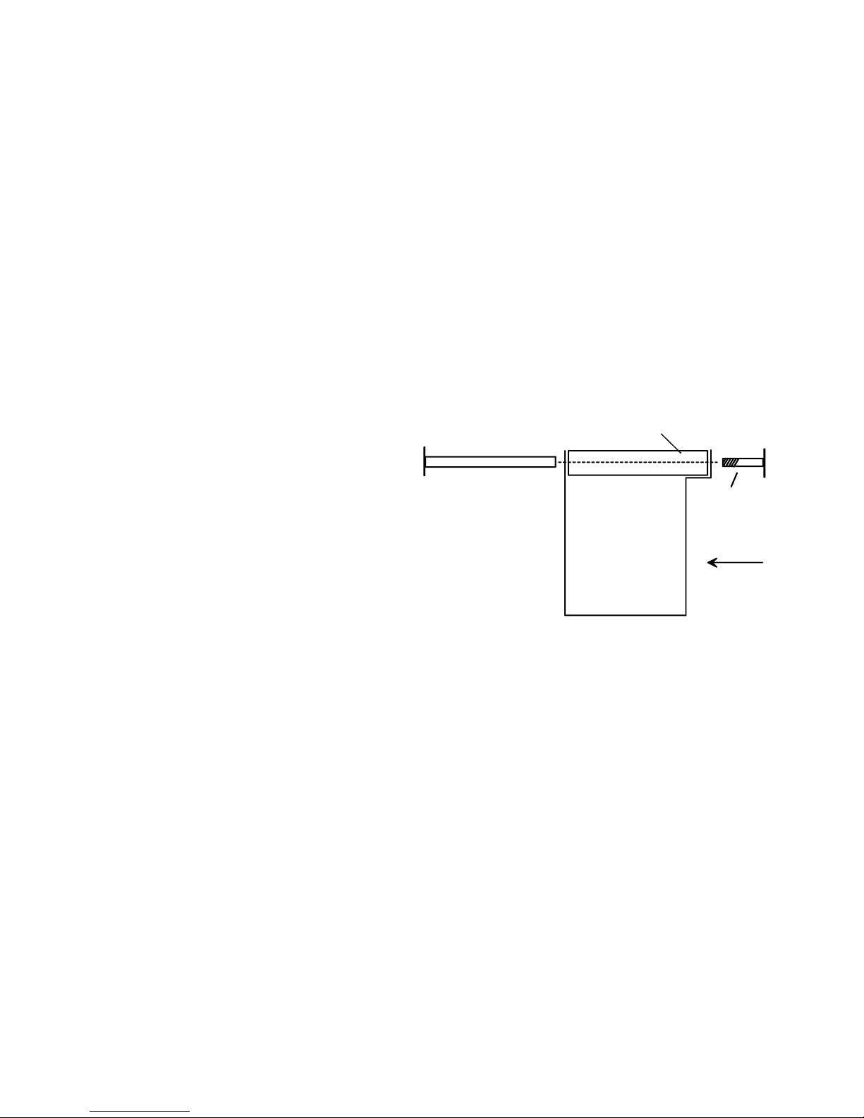
Finally, the cover mounts utilizing the binder
posts and matching screws. Do not mount
the cover yet as you will want to check
adjustment of the proximity switch array.
Mounting the cover is the final step when
everything else is complete. When you do
mount the cover, the long binder post
inserts into the cover and goes through the
corresponding hole in the sub-plate. See
the drawing to the right. The matching
screw secures it. Note that the screw
affixes the binder post from the side of the
cover that includes the opening for the
Magnalock face. This is so the blank head of the post faces away from the door. This reduces
the risk of tampering and looks better. If you have an aluminum frame glass door with a
blade stop, you will have to drill through holes through the blade stop (or remove a small
section) to pass the binder posts though for final cover mounting.
3. WIRING THE MXD
The sole purpose of the MXD is to send an initiate signal to Securitron’s model XDT delayed
exit logic timer. The signal is furnished from the two flying leads attached to the proximity switch
array on the sub-plate. These two wires are closed when the door is in the normal closed
position and they open when the door is pushed open approximately one inch which takes up
the slack in the assembly provided by the MXD sex bolt. The leads should be pulled up into the
same hole you make in the sub-plate with the Magnalock cable. They connect to terminals “+”
and “IN” on the XDT circuit board (see EXD instructions).
4. ADJUSTING THE DOOR MOVEMENT STROKE
When you have finished wiring of the complete door installation, put the door through its delayed
exit sequence several times by slowly opening the door to initiate delay. The factory set position
SUB-PLATE
COVER
BINDER POST SCREW
OPENING
FOR MAGNET

Rev. A.2, 6/00 Page- 6
of the proximity switch array should allow considerable door movement prior to the delay
starting. The benefit of this large movement (approximately 1”) is the avoidance of false
initiation through (for example) the door being rattled from the outside or moved by the wind.
The movement stroke can be reduced by loosening the screws that hold the proximity switch
array to the sub-plate and sliding the array farther from the door. Securitron recommends that
this be done only in special situations. Examples would be if the door will not physically move
far enough to reliably initiate delay without reducing the stroke because the door is thicker than
1 3/4” and you have not added a spacer to the MXD sex bolt (see Section 2.3.1) or if you
deliberately want to mechanically limit the amount of door movement because of high security
concerns for that door (you wish to avoid the possible insertion of a crowbar).
5. REDUNDANT OPERATION AND TAMPER PROOFING
The proximity switch array contains three proximity switches for the following reasons. Two are
wired such that if either switch de-energizes as the permanent magnet is separated from the
switch array, the delay initiate signal will be given. This provides redundant reliability of safe
egress operation as single component failure will not stop the MXD from allowing egress.
The third proximity protects against a certain type of tampering. It is wired such that if another
permanent magnet is brought near to it, it will initiate the delay. It is positioned so that it never
gets close enough to the permanent magnet pack on the door to trigger. A building guard
however may wish to defeat the function of the MXD in letting people go out, either because he
imagines that he is doing a useful thing by increasing security (at the expense of life safety) or
because he wishes to avoid having to respond to door alarms. If the guard comes to
understand that a permanent magnet is mounted behind the strike and that separation of this
magnet pack from the lock housing initiates the delay signal, he may try to defeat this function
by placing an external magnet around the housing. This will generally result in the delay
initiating from the third “tamper” proximity unit. The MXD therefore includes a strong defense
against tampering with its safety function. This function should nevertheless be periodically
tested by building management as maintenance of life safety should be the paramount
concern.

Rev. A.2, 6/00 Page- 7
MAGNACARE LIMITED LIFETIME WARRANTY
SECURITRON MAGNALOCK CORPORATION warrants that it will replace at customer’s request, at any time for
any reason, products manufactured and branded by SECURITRON.
SECURITRON will use its best efforts to ship a replacement product by next day air freight at no cost to the
customer within 24 hours of SECURITRON’s receipt of the product from customer. If the customer has an account
with SECURITRON or a valid credit card, the customer may order an advance replacement product, whereby
SECURITRON will charge the customer’s account for the price of the product plus next day air freight, and will
credit back to the customer the full amount of the charge, including outbound freight, upon SECURITRON’s receipt
of the original product from the customer.
SECURITRON’s sole and exclusive liability, and customer’s sole remedy, is limited to the replacement of the
SECURITRON product when delivered to SECURITRON’s facility (freight and insurance charges prepaid by
customer). The replacement, at SECURITRON’s sole option, may be the identical item or a newer unit which
serves as a functional replacement. In the event that the product type has become obsolete in SECURITRON’s
product line, this MAGNACARE warranty will not apply. This MAGNACARE warranty also does not apply to
custom, built to order, or non-catalog items, items made by others (such as batteries), returns for payment,
distributor stock reductions, returns seeking replacement with anything other than the identical product, or products
installed outside of the United States or Canada. This MAGNACARE warranty also does not apply to removal or
installation costs.
SECURITRON will not be liable to the purchaser, the customer or anyone else for incidental or consequential
damages arising from any defect in, or malfunction of, its products. SECURITRON does not assume any
responsibility for damage or injury to person or property due to improper care, storage, handling, abuse, misuse, or
an act of God.
EXCEPT AS STATED ABOVE, SECURITRON MAKES NO WARRANTIES, EITHER EXPRESS OR IMPLIED, AS
TO ANY MATTER WHATSOEVER, INCLUDING WITHOUT LIMITATION THE CONDITION OF ITS PRODUCTS,
THEIR MERCHANTABILITY OR FITNESS FOR ANY PARTICULAR PURPOSE.
SECURITRON MAGNALOCK CORP., 550 Vista Blvd., Sparks NV 89434 USA
Tel: (775) 355-5625 l(800) MAGLOCK lFax: Mkt. (775) 355-5636, Fax: Admin. (775) 355-5633
An ASSA ABLOY Group company
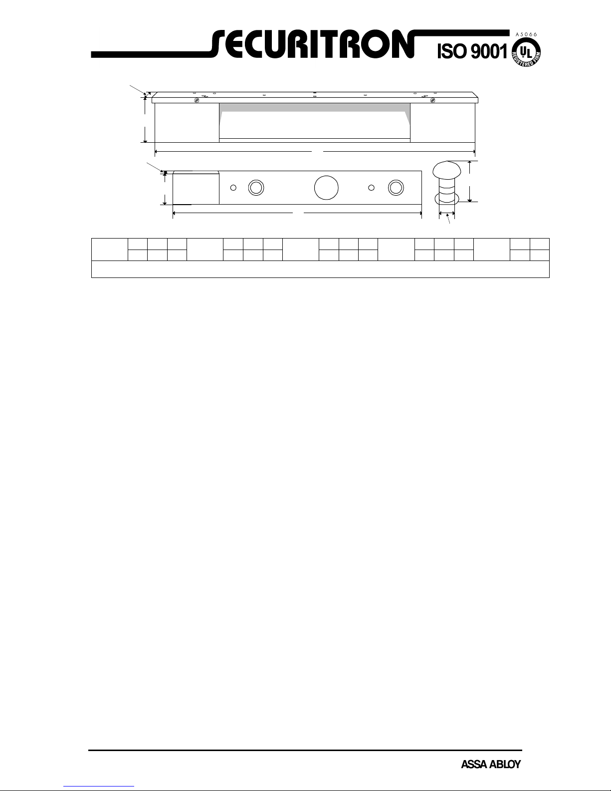
A
13
B
2.5
C
2.1
MODEL
MXD-32
HOUSING
NOTE: ALL DIMENSIONS IN INCHES. FASTENERS NOT SHOWN
A
B
CA
B
C
B
A
A
9.375
B
1.625
C
.875
MODEL
MXD-32
BACK PLATE
A
13
B
3.5
C
2.6
MODEL
MXD-62
HOUSING
A
9.375
B
1.625
C
.875
MODEL
MXD-62
BACK PLATE
A
1
B
3
MODEL
MXD-32/62
SEX BOLT
DOOR MOVEMENT HARDWARE MXD-32/62:
The Door Movement Hardware shall be produced by an ISO 9001 certified manufacturer. The door
movement hardware shall be of a modular nature and not an integral part of the magnetic lock. It shall
consist of an aluminum sub-plate for lock mounting, an adjustable magnetic switch for system initiation, a
spring loaded plunger sex bolt (to allow for door movement), a strike armature sub-plate with permanent
magnetic actuator and a stainless steel assembly cover for aesthetics and increased security. The door
movement hardware shall be tolerant to door play and shall be adjustable to allow a full 3/8” to a full 1” of
door movement to accomplish delay system initiation.
Securitron model MXD-32/62 door movement hardware.
MXDspc.doc
Rev. 5/99
This manual suits for next models
1
Table of contents
Popular Door Opening System manuals by other brands

Norton
Norton 8000 Series installation instructions

hawa
hawa HAWA-Motronic 60 Installation and commissioning instructions

Langer & Laumann
Langer & Laumann QKS6 user manual

CornellCookson
CornellCookson FS-150EP Series Installation instructions and operation manual

AGS
AGS Opera Bit user guide

Uaccess
Uaccess Eternity EDC700 Series Installation

drive mobil
drive mobil Doormatic Operating instructions and safety guide

Automatic Technology
Automatic Technology DOMINATOR EasyRoller instruction manual

Falcon
Falcon SC81 installation instructions

Command access
Command access MLRK1 Series instructions

EZ-ACCESS
EZ-ACCESS CONCIERGE Series installation manual

Yale
Yale 50 Series installation instructions


