Security Chimneys Secure Temp S2100 User manual

Secure Temp®S2100 and ASHT
www.securitychimneys.com
800-361-4909 (US) 800-667-3387 (Canada)
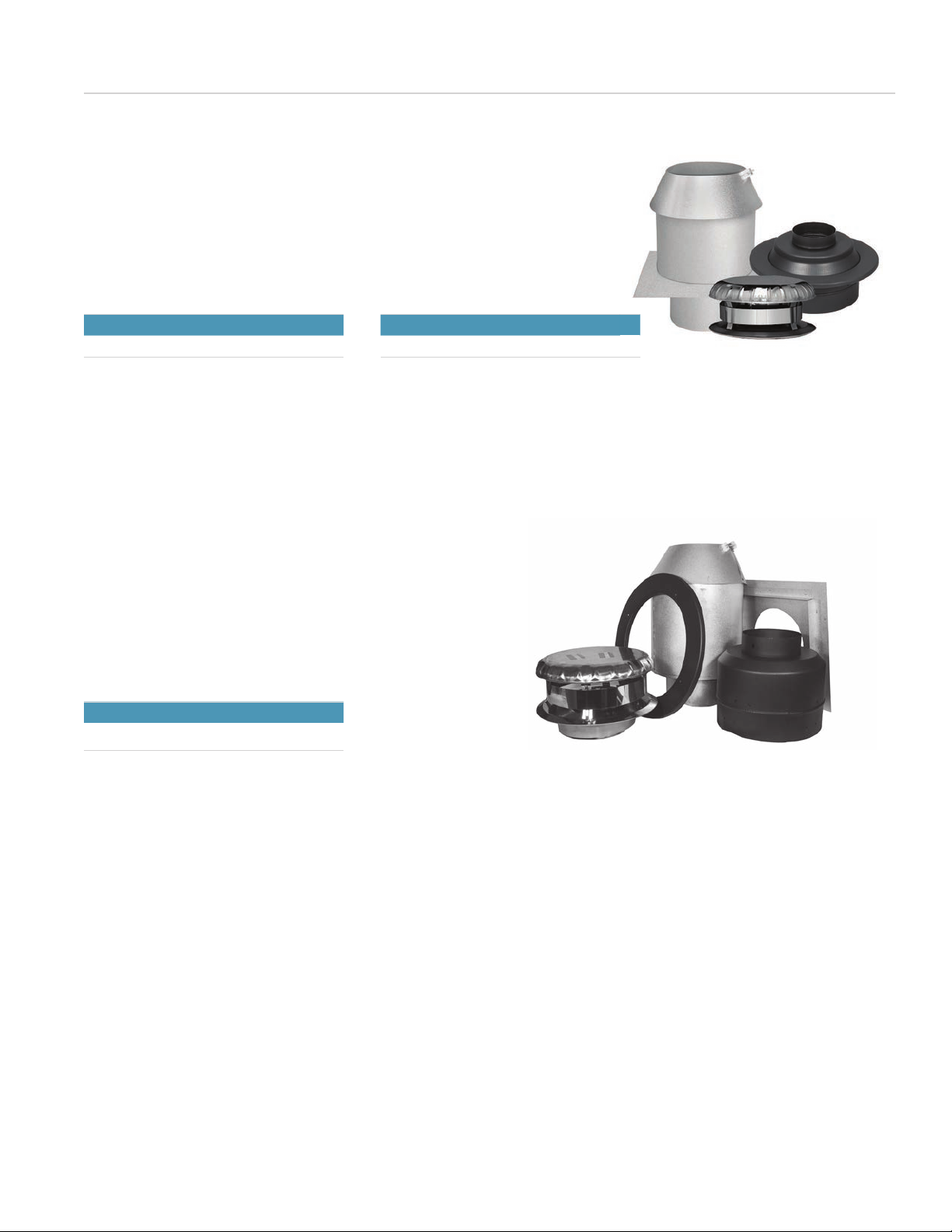
High-Temperature Factory-Built Chimneys
APPLICATIONS
The Secure Temp S2100 has been designed to widely
exceed existing safety standards while offering the best
available chimney system. It has been designed for use with
wood, gas, oil, or coal-burning appliances. The Secure Temp
S2100 high-temperature chimney is certied by Intertek
Testing Services (Warnock Hersey) to ULC S629 standards
for diameters of 6, 7 and 8 inches.
A TRADITION OF EXCELLENCE
For over 50 years, Security Chimneys has been an innovator
in the venting eld and a market leader in North America.
Instrumental in the company’s growth has been an ongoing
focus on product improvement and the introduction of new,
innovative products. This drive for excellence has given rise
to the Secure Temp S2100, one of the most popular lines
of venting products in North America. These high-quality
products ensure that end-users benet from maximum
safety and proven corrosion protection.
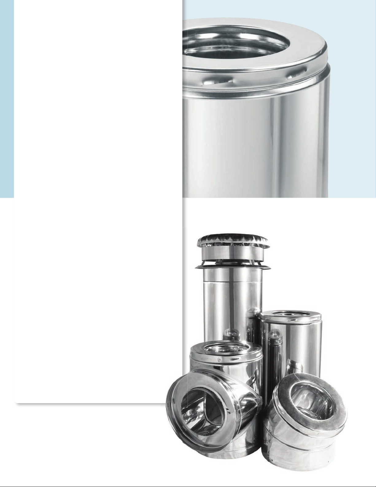
INNOVATIVE COMPOSITION AND EASE OF INSTALLATION
The use of stainless steel, selected for its resistance to high
temperatures and corrosion, lends outstanding durability to
the Secure Temp S2100 high-temperature chimneys. Secure
Temp S2100 has a temperature rating of 650°C (1200°F);
max. continuous, 760°C (1400°F) brief forced red; and
1150°C (2100°F) 3 x 30 minutes, tested.
All chimneys feature 2 inches (S2100) of superior-quality,
high-density Secura Plus insulation. This exclusive insulation
keeps the temperature of the outer casing relatively low,
keeping safety features as simple as possible. The S2100,
with 2 inches of insulation, is well-suited for outside
installations in areas where very cold temperatures occur.
All Secure Temp S2100 high-temperature chimneys,
regardless of diameter, can be installed as close as 2 inches
from combustible materials.
The S2100 also features fast and easy Twist-Lock assembly.
Lengths and universal ttings t together and lock into place
by twisting one-eighth of a turn. No other part is needed to
ensure the chimney’s structural stability, keeping installation
time to a minimum.
Secure Temp®S2100

Features Benefits
Twist-Lock stainless steel coupler system with
1-inch overlap
• No screws or other attachments required
• Fast and easy installation with one-eighth of a turn
Stainless steel inner lining
• Provides smoother surface
• Little restriction of ue gases even with an elbow
• Outstanding corrosion resistance
Two inches (S2100) of exclusive
Secura Plus insulation
• No shifting of the insulation
• Keeps cooling of gas temperatures minimal which stabilizes at
high temperatures
• Reduces condensation and creosote buildup
• Increases appliance performance by providing stable draft
• Low surface temperature
• Minimum 2-inch safety clearance to combustible materials in
all diameters
Fast venting of combustion products • Delivers a stable and powerful draft
Stainless steel outer casing • Supports the structural load
• Corrosion resistance
Inner liner attached only to the male coupler • Free-oating inner wall means no need for expansion joints
• Unhindered expansion with rising temperatures
Lightweight - 6-inch diameter, 8.9lb per
linear foot
• Delivers a more user-friendly design
• For support, see "Loadbearing Capacity" chart on page 4.
SECURITY CHIMNEYS
SECURE TEMP 2100
CHIMNEYS FOR WOOD
STOVE APPLICATIONS
800-361-4909 (US) | 800-667-3387 (Canada) 2
Offset and rise calculation
The following steps will help determine
the lengths required for an installation:
1. Determine the offset required in view
of the obstacles that must be avoided.
2. Refer to the “Offset/Rise Chart" to
determine the elbows required as well as
the insulated lengths needed.
3. Check the corresponding offset height
dimensions.
ELBOW OFFSET & RISE CHART
One length between elbows
Angle Dia. 8" 12" 18" 24" 36" 48"
15 6" & 8"
Offset 3-5/16" 4-5/16" 5-7/8" 7-7/16" 10-1/2" 13-5/8"
Rise 16" 19-7/8" 25-11/16" 31-1/2" 43-1/16" 54-5/8"
Two lengths between elbows
8" & 48" 12" & 48" 18" & 48" 24" & 48" 36" & 48" 48" & 48"
Offset 15-1/2" 16-1/2" 18-1/16" 19-5/8" 22-3/4" 25-13/16"
Rise 61-7/16" 65-1/4" 71-1/16" 76-7/8" 88-1/2" 100-1/16"
Angle Dia. 8" 12" 18" 24" 36" 48"
30 6" & 8"
Offset 7-3/8" 9-3/8" 12-3/8" 15-3/8" 21-3/8" 27-3/8"
Rise 20-11/16" 24-3/16" 29-3/8" 34-9/16" 44-15/16" 55-5/16"
Two lengths between elbows
8" & 48" 12" & 48" 18" & 48" 24" & 48" 36" & 48" 48" & 48"
Offset 30-7/8" 32-7/8" 35-7/8" 38-7/8" 44-7/8" 50-7/8"
Rise 61-3/8" 64-7/8" 70-1/16" 75-1/4" 85-5/8" 96"
Angle Dia. 8" 12" 18" 24" 36" 48"
45 6" & 8"
Offset 10-5/16" 13-3/16" 17-3/8" 21-5/8" 30-1/8" 38-5/8"
Rise 17-13/16" 20-5/8" 24-7/8" 29-1/8" 37-5/8" 46-1/8"
Two lengths between elbows
8" & 48" 12" & 48" 18" & 48" 24 "& 48" 36" & 48" 48" & 48"
Offset 43-7/16" 46-1/4" 50-1/2" 54-3/4" 63-1/4" 71-11/16"
Rise 50-15/16" 53-3/4" 58" 62-1/4" 70-3/4" 79-3/16"
9
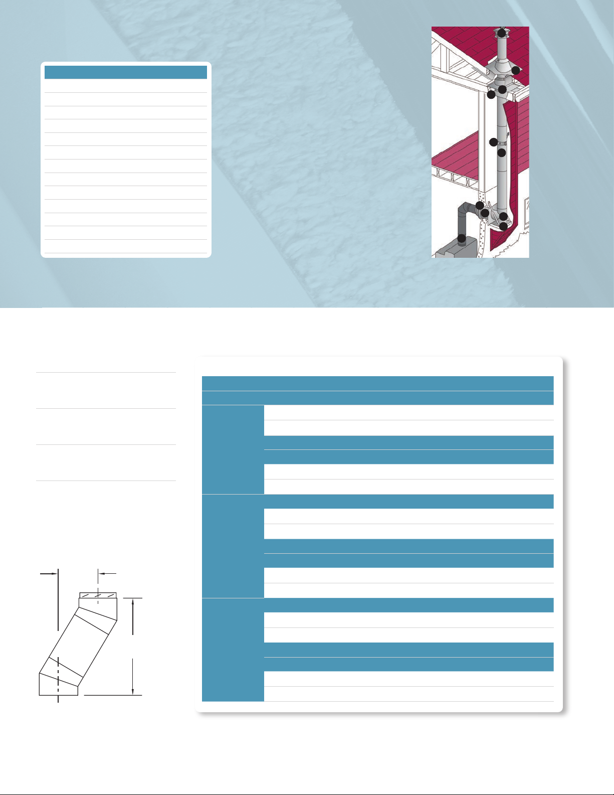
Exterior installation to
a wood stove.
OFFSET
RISE
INSTALLATION KEY
1Black Stove Pipe
2Finishing Cone
3Insulated Wall Thimble
4Tee Support
5Insulated Tee
6Insulated Length
7Universal Wall Band
8Insulated Attic Radiation Shield
9Adjustable Roof Flashing w/ Storm Collar
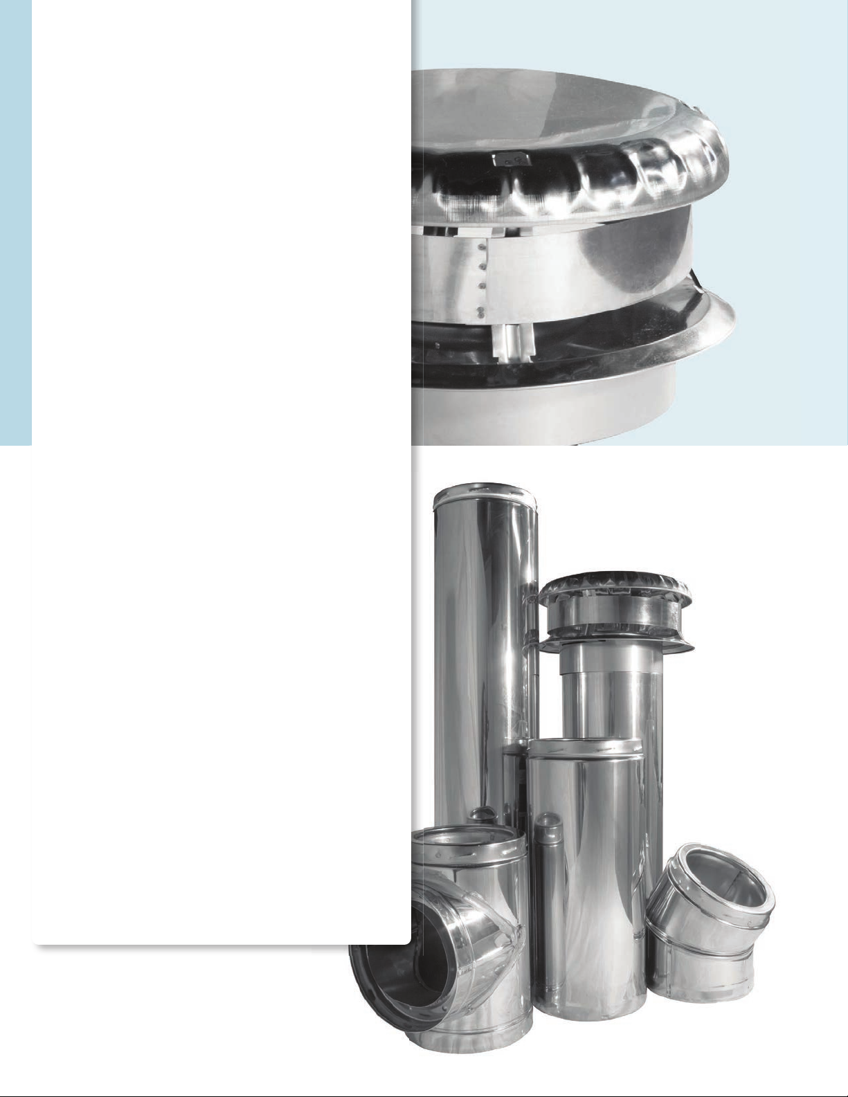
10 Rain Cap
11 Firestop
12 Finishing Support
13 Anchor Plate
10
9
8
11
7
6
5
4
3
2
1
3 Security Chimneys | www.securitychimneys.com

Installation
Assembly always requires the male coupler to be
positioned upwards. Size the chimney in accordance
with the appliance instruction manual. Map out the
chimney path closest to the heating unit. Prior to
installation, consult the detailed installation manual
included with the support components.
Any replaces and controlled combustion units
can be connected to the Secure Temp S2100,
since it has been certied, independently, to ULC
S629M standards.
SAFETY
Security Chimneys Secure Temp S2100 chimneys
can be installed as close as 2 inches to combustible
materials, regardless of the diameter to be used.
Radiation shields and appropriate supports must be
used to maintain a safe clearance as the chimney
passes through oors and combustible partitions.
LOADBEARING CAPACITY
Maximum height
Ø int. 6" 7" 8"
Wall support 30' 28' 26'
Adjust. wall/tee
support 30' 28' 26'
Roof support 20' 18' 16'
Offset support 18' 16' 14'
Cathedral support 30' 28' 26'
Sq. cathedral
support 30' 28' 26'
Finish support 30' 28' 26'
Offset/Wall support 24' 21' 20'
Reduced Clearance
support 30' 28' 26'
SIZE OF OPENINGS*
Hole size (framing)
Ø int. 6" 7" 8"
Roof support 14" 15" 16"
Radiation
shield 14" 15" 16"
Cathedral
support 14-3/8" 14-3/8" 14-3/8"
Sq. cathedral
support 14-3/8" 14-3/8" 14-3/8"
Finish
support 14-3/8" 14-3/8" 14-3/8"
Reduced
Clearance
support
12" 13" 14"
SECURE TEMP S2100 GENERAL SPECIFICATIONS
Ø int. Ø ext. Insulation
thickness
Weight
lb./ft.*
Twist-Lock
assembly
Clearance to
combustible
6" 10' 2" 8.9 YES 2"
7" 11" 2" 9.9 YES 2"
8" 12" 2" 10.9 YES 2"
Temperature Rating Period of Operation
650° C (1200°F) Max. continuous
760° C (1400°F) Brief forced red
1150° C (2100°F) 3 x 30 minutes, tested
Interior installation on a wood
stove using a nishing support. Chimney installed on a
masonry replace.
10
9
8
11
6
1
12
10
9
8
7
11
6
13
800-361-4909 (US) | 800-667-3387 (Canada) 4
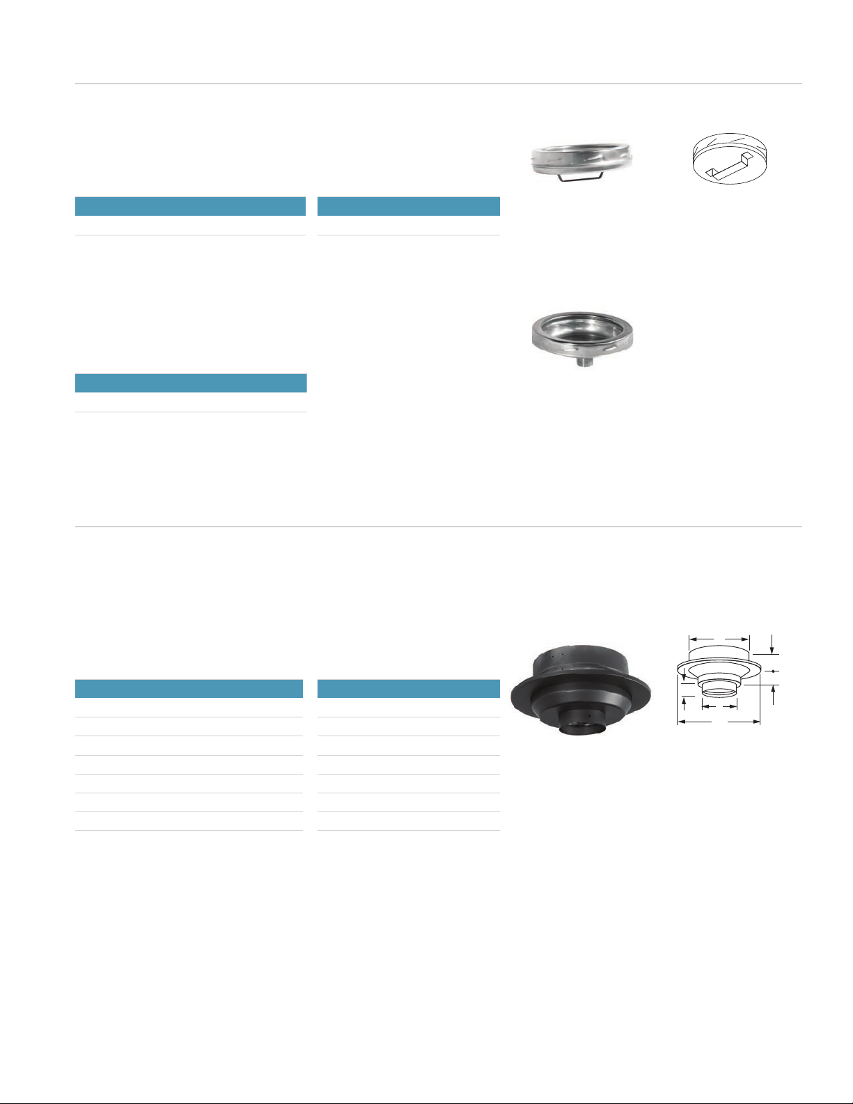
Secure Temp®ASHT
Secure Temp
APPLICATIONS
The Secure Temp ASHT is one of the most extensively
used factory-built venting systems in North America. It has
been specially developed for use with oil and gas burning
heating appliances and certied wood-burning replaces.
The Secure Temp ASHT high-temperature chimney is
certied by Intertek Testing (Warnock Hersey) to ULC S604
standards and ULC S610 (on wood-burning replaces) for
all diameters of 5, 6, 7, 8 and 10 inches.
CERTIFICATION
The Secure Temp ASHT high-temperature chimney is certied
by Intertek Testing (Warnock Hersey) to:
• ULC S604 standards for all diameters of 5, 6, 7, 8, and
10 inches.
• ULC S610 (on wood-burning replaces) for all diameters of
5, 6, 7, 8 and 10 inches.
• ULC S629 for wood stove applications in diameters of 6, 7,
and 8 inches.
INSTALLATION
Assembly always requires the male coupler to be positioned
upwards. Size the chimney in accordance with the appliance
instruction manual. Map out the chimney path closest to the
heating unit.
For wood stove applications, a third pipe (premium shield) is
required for inside installation where the chimney is enclosed
between two oors (see premium shield accessories section).
Prior to installation, consult the detailed installation manual
included with the support components.
SAFETY
Security Chimneys's Secure Temp ASHT chimneys can
be installed as close as 2 inches to combustible materials,
regardless of the diameter to be used. Radiation shields
and appropriate supports must be used to maintain a
safe clearance as the chimney passes through oors and
combustible partitions.
Some radiation shields in the Secure Temp ASHT line
have been designed specically for use with wood-
burning replaces. For the use of Secure Temp ASHT with
manufactured wood replaces, refer to the instruction of
these products.
Secure Temp®ASHT

SECURITY CHIMNEYS
SECURE TEMP ASHT
VENT SYSTEM
FOR CHIMNEYS
Twist-Lock stainless steel coupler system with 1-inch overlap
• No screws or other attachments required
• Fast and easy installation with one-eighth of a turn
Stainless steel inner lining
• Provides smoother surface
• Little restriction of ue gases even with an elbow
• Outstanding corrosion resistance
One inch of exclusive Secura Plus insulation
• No shifting of the insulation
• Keeps cooling of gas temperature minimal, which stabilizes
at high temperatures
• Reduces condensation and creosote buildup
• Low surface temperature
• Minimum 2-inch safety clearance to combustible materials
in all diameters
Fast venting of combustion products
• Delivers a stable and powerful draft
Stainless steel outer casing
• Supports the structural load
• Corrosion resistance
Inner liner attached only to the male coupler
• Free-oating inner wall means no need for expansion joints
• Unhindered expansion with rising temperatures
Lightweight – 6-inch diameter, 5.2 lb. per linear foot
• Delivers a more user-friendly design
• For support, see “Loadbearing Capacity" chart on page 4.
1
3
2
4
5
6
7
1
2
3
4
5
6
7

Offset and rise calculation
The following steps will help determine
the lengths required for an installation:
1. Determine the offset required in view
of the obstacles that must be avoided.
2. Refer to the “Offset/Rise Chart" to
determine the elbows required as well as
the insulated lengths needed.
3. Check the corresponding offset height
dimensions.
ELBOW OFFSET & RISE CHART
One length between elbows
Angle Dia. 8" 12" 18" 24" 36" 48"
15 6" & 8"
Offset 3-5/16" 4-5/16" 5-7/8" 7-7/16" 10-1/2" 13-5/8"
Rise 15-11/16" 19-9/16" 25-3/8" 31-3/16" 43-3/4" 54-3/8"
Two lengths between elbows
8" & 48" 12" & 48" 18" & 48" 24" & 48" 36" & 48" 48" & 48"
Offset 15-3/8" 16-7/16" 18" 19-1/2" 22-5/8" 25-3/4"
Rise 60-15/16" 64-3/16" 70-9/16" 76-3/8" 87" 99-9/16"
Angle Dia. 8" 12" 18" 24" 36" 48"
30 6" & 8"
Offset 7-7/16" 9-7/16" 12-7/16" 15-7/16" 21-7/16" 27-7/16"
Rise 20" 23-1/2" 28-11/16" 33-7/8" 44-1/4" 54-11/16"
Two lengths between elbows
8" & 48" 12" & 48" 18" & 48" 24" & 48" 36" & 48" 48" & 48"
Offset 30-13/16" 32-13/16" 35-13/16" 38-13/16" 44-13/16" 50-13/16"
Rise 60-9/16" 64" 69-1/4" 74-7/16" 84-13/16" 95-1/4"
Angle Dia. 8" 12" 18" 24" 36" 48"
45 6" & 8"
Offset 10-5/16" 13-3/16" 17-3/8" 21-5/8" 30-1/8" 38-5/8"
Rise 17-13/16" 20-5/8" 24-7/8" 29-1/8" 37-5/8" 46-1/8"
Two lengths between elbows
8" & 48" 12" & 48" 18" & 48" 24 "& 48" 36" & 48" 48" & 48"
Offset 43-7/16" 46-1/4" 50-1/2" 54-3/4" 63-1/4" 71-11/16"
Rise 50-15/16" 53-3/4" 58" 62-1/4" 70-3/4" 79-3/16"
Fireplace through exterior
insulated chase
OFFSET
RISE
8
7
6
5
4
3
2
1
INSTALLATION KEY
1Insulated Elbow
2Insulated Wall Radiation Shield
3Insulated Length
4Universal Offset Support
5Insulated Attic Radiation Shield
6Adj. Roof Flashing w/ Storm Collar
7Rain Cap
8Firestop
9Connector
10 Base Tee for Twin Connections
11 Floor Support
12 Universal Roof Support
13 Flat Roof Flashing w/ Storm Collar
14 Black Stove Pipe
15 Finishing Support
16 Telescopic Rigid Shield
17 Radiation Shield Connector
18 Storm Collar
19 Radiation Shield Connector Firestop
7 Security Chimneys | www.securitychimneys.com

Installation
Assembly always requires the male coupler to be
positioned upwards. Size the chimney in accordance
with the appliance instruction manual. Map out the
chimney path closest to the heating unit. Prior to
installation, consult the detailed installation manual
included with the support components.
SAFETY
Security Chimneys International’s Secure Temp
ASHT chimneys can be installed as close as 2
inches to combustible materials, regardless of
the diameter to be used. Radiation shields and
appropriate supports must be used to maintain
a safe clearance as the chimney passes through
oors and combustible partitions.
Some radiation shields in the Secure Temp ASHT
line have been designed specically for use with
wood-burning replaces. For the use of Secure
Temp ASHT with manufactured wood replaces,
refer to the instructions of these products.
LOADBEARING CAPACITY
Maximum
height
Ø int. 5" 6" 7" 8" 10"
Floor support 32' 32' 32' 32' 32'
Tee support 63' 63' 55' 48' 39'
Adjust. tee/
wall support 63' 63' 55' 48' 39'
Roof support 42' 34' 27' 24' 20'
Offset
support -- 28' 24' 20' 14'
Sq. cathedral
support -- 60' 50' 45' 35'
Finishing
support -- 75' 65' 59' --
Adj. square
support w/
faming arms
and coupler
-- 27' 22' -- --
Offset/Wall
support -- 28' 24' 20' 14'
Reduced
Clearance
support
-- 60' 50' 45' --
SIZE OF OPENINGS*
Hole size
(framing)
Ø int. 5" 6" 7" 8" 10"
Floor
support
11-
3/8"
12-
3/8"
13-
3/8"
14-
3/8"
16-
3/8"
Sq.
cathedral
support
-- 14-
3/8"
14-
3/8"
14-
3/8" --
Finishing
support
14-
3/8"
14-
3/8"
14-
3/8"
14-
3/8" --
Roof
support
11-
3/8"
12-
3/8"
13-
3/8"
14-
3/8"
16-
3/8"
Wall
thimble
11-
3/8"
12-
3/8"
13-
3/8"
14-
3/8"
16-
3/8"
Firestop 11-
3/8"
12-
3/8"
13-
3/8"
14-
3/8"
16-
3/8"
Reduced
Clearance
support
-- 10" 11" 12" --
SECURE TEMP ASHT GENERAL SPECIFICATIONS
Ø int. Ø ext. Insulation
thickness
Weight
lb./ft.*
Twist-Lock
assembly
Clearance to
combustible
5" 7" 1" 4.1 YES 2"
6" 8" 1" 5.2 YES 2"
7" 9" 1" 6.4 YES 2"
8" 10" 1" 7.2 YES 2"
10" 12" 1" 8.9 YES 2"
Temperature Rating Period of Operation
538°C (1000°F( Max. continuous
760°C (1400°F) Brief forced red
1150°C (2100°F) 3 x 30 minutes, tested
Residential furnace and
water heater Chimney with several
replaces
10
9
11
9
8
8
3
12
13
5
7
3
3
8
11
5 1
Chimney on a wood
stove
16
14
15
3
17
18
19
6
7
800-361-4909 (US) | 800-667-3387 (Canada) 8
Coding Logic:
This document contains a description of each of the parts for the Secure Temp ASHT and S2100 systems, as well as their respective applications.
Each part has a reference letter that identies the product.
The following examples of our coding system should make it easier for you to identify and order the components you need.
ASHT0
Code 6L36 6FA
Size 6Interior diameter 6Interior diameter
Reference LInsulated length FFlashing
Specicity 36 36" length AAdjustable
S21000
Code 6XL36 6XRSMI30
Size 6Interior diameter 6Interior diameter
Reference XL Insulated length XRS Radiation shield
Specicity 36 36" length MI Insulated wall
30 30º angle
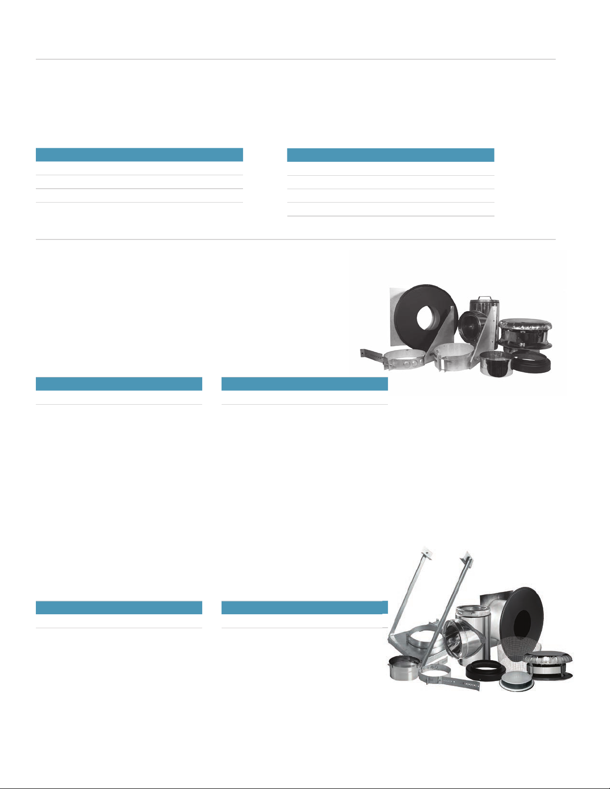
Wall Support Kit for 6" & 7" Diameters
Kit includes:
Insulated tee, twist lock tee cap, adjustable tee support, insulated wall
radiation shield, ue extension, double wall decorative collar, wall band, and
rain cap.
Can use for through the wall installations.
Pipe not included.
ASHT
Ref. 6WSK, 7WSK
Only available in 6" & 7" Diameters.
Exterior Kit for 6" & 7" Diameters
Kit includes:
Insulated tee with insulated tee cap, adjustable tee support, insulated wall
thimble, decorative collar single wall, ue extension, and decorative collar
double wall, spark arrestor, rain cap, and wall band.
ASHT
Ref. 6EK-2. 7EK
Only available in 6" & 7" Diameters.
S2100
Ref. 6XWSK, 7XWSK
Only available in 6" & 7" Diameters.
S2100
Ref. 6XKE, 7XKE
Only available in 6" & 7" Diameters.
Kits
9 Security Chimneys | www.securitychimneys.com
Kits
Interior Kit
Kit includes:
Finishing support with coupler, 2 piece attic insulation shield, and rain cap.
Use for interior installations only.
ASHT
Ref. 6IK-1
Only available in 6" Diameter.
S2100
Ref. 6XKI, 7XKI
Only available in 6" Diameter.
Interior New Construction Kit
Kit includes:
Finishing support with removable outer trim collar, adjustable insulated
attic radiation shield, and rain cap.
Use for new home construction with through the roof installation.
ASHT
Ref. 6IKNC
Only available in 6" Diameter.
800-361-4909 (US) | 800-667-3387 (Canada) 10

Lengths
Insulated Lengths
A
ASHT: Five diameters and six standard effective lengths featuring a 1/8-turn Twist-
Lock assembly.
S2100: Three diameters and six standard effective lengths featuring a 1/8-turn Twist-
Lock assembly.
Various lengths may be combined to obtain the required installation height.
ASHT
Ref. L
Ø int. 5" 6" 7" 8" 10"
Ø ext. 7" 8" 9" 10" 12"
Lb./ft. 4.1 5.2 6.4 7.2 8.9
A1-1/4" 1-1/4" 1-1/4" 1-1/4" 1-1/4"
Length
Available
Effective
Length
Ø 5 to 10 8" 6-3/4"
12" 10-3/4"
18" 16-3/4"
24" 22-3/4"
36" 34-3/4"
48" 46-3/4"
S2100
Ref. XL
Ø int. 6" 7" 8"
Ø ext. 10" 11" 12"
Lb./ft. 8.9 9.9 10.9
A1" 1" 1"
Length
Available
Effective
Length
Ø 6 to 8 8" 7"
12" 11"
18" 17"
24" 23"
36" 35"
48" 47"
Adjustable Lengths
5’ (60”)
A support must
be installed
within this area.
3”
min.
overlap
11 1/4”
A
A support must
be installed within
this area
Used in combination with straight insulated lengths, the adjustable length makes it
possible to t a Secure Temp length perfectly. IMPORTANT: The adjustable length is not
designed as a loadbearing component. Its vertical installation requires an appropriate
support on the section above it to bear the weight of the remaining installation.
ASHT
Ref. LA
Ø int. 5" 6" 7" 8" 10"
A11-1/4" 11-1/4" 11-1/4" 11-1/4" 11-1/4"
S2100
Ref. XLA
Ø int. 6" 7" 8"
A11-1/4" 11-1/4" 11-1/4"
11 Security Chimneys | www.securitychimneys.com

Elbows
15ºInsulated Elbow
A
B
Allows the 15° offset of a chimney. Designed to bypass an obstacle, such as a joist. A
maximum of two offsets (4 elbows) is allowed.
ASHT
Ref. E15
Ø int. 5" 6" 7" 8" 10"
Ø ext. 7" 8" 9" 10" 12"
Lb./ft. 1/2" 1/2" 1/2" 1/2" 1/2"
A4-1/2" 4-1/2" 4-1/2" 4-1/2" 4-1/2"
S2100
Ref. XE15
Ø int. 6" 7" 8"
Ø ext. 10" 11" 12"
A 5/8" 5/8" 5/8"
B4-3/4" 4-3/4" 4-3/4"
30ºInsulated Elbow
A
B
Allows the 30° offset of a chimney. Designed to bypass an obstacle, such as a joist. A
maximum of two offsets (4 elbows) is allowed.
ASHT
Ref. E30
Ø int. 5" 6" 7" 8" 10"
Ø ext. 7" 8" 9" 10" 12"
Lb./ft. 2" 2" 2" 2" 2"
A7-1/2" 7-1/2" 7-1/2" 7-1/2" 7-1/2"
S2100
Ref. XE30
Ø int. 6" 7" 8"
Ø ext. 10" 11" 12"
A 1-15/16" 1-15/16" 1-15/16"
B7-5/16" 7-5/16" 7-5/16"
45ºInsulated Elbow
A
B
Allows the 45° offset of a chimney. Designed to bypass an obstacle, such as a joist.
A maximum of two offsets (4 elbows) is allowed. The chimney’s angle of inclination
must not deviate more than 45° from the vertical position.
ASHT
Ref. E45
Ø int. 5" 6" 7" 8" 10"
Ø ext. 7" 8" 9" 10" 12"
Lb./ft. 3" 3" 3" 3" 3"
A6-7/8" 6-7/8" 6-7/8" 6-7/8" 6-7/8"
S2100
Ref. XE45
Ø int. 6" 7" 8"
Ø ext. 10" 11" 12"
A 3" 3" 3"
B6-7/8" 6-7/8" 6-7/8"
800-361-4909 (US) | 800-667-3387 (Canada) 12

Tees
Base Tee
Located at the base of the chimney, it makes it possible to connect the chimney to
a gas- or oil-burning appliance. It is recommended for interior installations only
and must be attached to a ue extension. The galvanized steel base tee comes
complete with a tee cap to provide access for inspection and cleaning. Available in
stainless (TBS).
ASHT & S2100
Ref. TB or TBS
Ø int. 6" 7" 8" 10"
A 23" 24" 25" 27"
B18" 18-1/2" 19" 20"
C5" 5-1/2" 6" 7"
D5-1/2" 6" 6-1/2" 7-1/2"
Double Base Tee
This component makes it possible to connect two appliances, such as a furnace
and a water heater to the SecureTemp™ ASHT chimney. The galvanized steel
base tee for twin connections comes with a tee cap (TC) to provide access for
inspection and cleaning.
ASHT & S2100
Ref. TBD
Ø int. 6" 7" 8" 10"
A 31" 33" 35" 39"
B18" 18-1/2" 19" 20"
C5" 5-1/2" 6" 7"
D5-1/2" 6" 6-1/2" 7-1/2"
E8" 9" 10" 12"
Insulated Tee
A
C
B
Located at the base of the chimney, it provides the horizontal connection to the
appliance. It is recommended for installations where a connector must pass through
an exterior wall because its insulation prevents the cooling of chimney gases. An
insulated tee cap (TCS) is included, which allows easy access for maintenance and
inspection.
The insulated tee cap (TCS) must be secured to the ue extension of the tee support
or adjustable tee support.
ASHT
Ref. TI
Ø int. 5" 6" 7" 8" 10"
Ø ext. 7" 8" 9" 10" 12"
A9-1/2" 10-1/2" 11-3/4" 13" 15"
B4-3/4" 5-1/4" 5-1/4" 6-1/4" 7-1/4"
C5-1/2" 6" 6-1/2" 7-1/4" 8-1/4"
S2100
Ref. XTI
Ø int. 6" 7" 8"
Ø ext. 10" 11" 12"
A 13-1/4" 13-1/4" 13-1/4"
B7" 7-1/2" 8"
C 7" 7-1/2" 8"
13 Security Chimneys | www.securitychimneys.com
Tees
Insulated Tee Cap (Twist-Lock)
Equipped with a Twist-Lock system, it makes it possible to seal the base of an
insulated tee when an adjustable wall support (SME or XSME) is used. It can be
removed, providing easy access for chimney maintenance and inspection. Its
insulation prevents the cooling of chimney gases, especially in exterior installations.
ASHT
Ref. TCI
Ø int. 5" 6" 7" 8" 10"
S2100
Ref. XTCI
Ø int. 6" 7" 8"
Drain Tee Cap
Fitted at the base of an insulated tee, it makes it possible to collect and drain
rainwater and condensates. The drain tee cap connects to a drain (NPT 0 1").
Removable, it provides easy access for chimney maintenance or inspection. Must be
combined with an adjustable wall support only.
ASHT
Ref. TCP
Ø int. 6" 7" 8" 10"
Supports
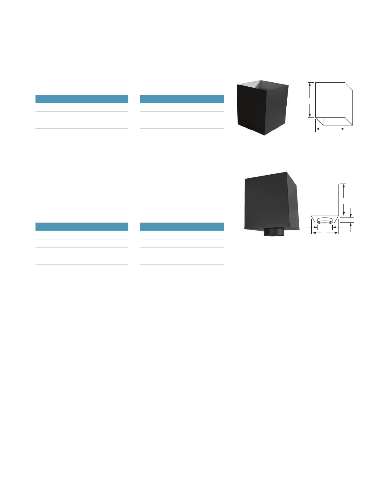
Finishing Support
A
B
C
D
E
F
This part supports the chimney from a ceiling. Designed to connect to both double-
wall and single-wall stove pipe, it is enhanced by a decorative black nish. Fits
between standard 16"- on-center joists. Must be attached to a frame built from the
joists. (Refer to chart on pg. 4 or 8 for loadbearing capacity and size of openings.)
A nishing support is also available with a removable collar for 5" (5SFCA and 6"
(6SFCA) installations.
ASHT
Ref. SFC
Ø int. 5" 6" 7" 8"
A 12" 12" 14-3/8" 14-3/8"
B5-1/4" 6-15/64" 7-1/4" 8-1/4"
C20" 20" 20" 20"
D 5-1/2" 5-1/2" 5-1/2" 5-1/2"
E3" 3" 3" 3"
F 2" 2" 2" 2"
S2100
Ref. XSFC
Ø int. 6" 7" 8"
A 14-3/8" 14-3/8" 14-3/8"
B6-15/16" 7-1/4" 8-1/4"
C20" 20" 20"
D 5-1/2" 5-1/2" 5-1/2"
E3" 3" 3"
F 2" 2" 2"
800-361-4909 (US) | 800-667-3387 (Canada) 14
Supports
Finishing Support with Removable Trim Collar
This part supports the chimney from a ceiling. Designed to connect to both double-
wall and single-wall stove pipe, it is enhanced by a decorative black nish. Fits
between standard 16"- on-center joists. Must be attached to a frame built from the
joists. (Refer to chart on page 4 or 8 for loadbearing capacity and size of openings.)
This nishing support has a removable trim collar for new construction installation.
A
B
C
D
E
F
ASHT
Ref. SFCA
Ø int. 5" 6"
A 12" 12"
B5-1/4" 6-15/64"
C20" 20"
D 5-1/2" 5-1/2"
E3" 3"
F 2" 2"
Insulated Reduced Clearance Support
Use with at, vaulted or cathedral ceilings. Certied to reduce clearance to combustibles from
the usual 2" (per side) down to a 1" (per side) for all diameters. This allows for a smaller hole
to be cut in the ceiling. Can connect to both double-wall stove pipe or single-wall stove pipe
with included adapter. Functions as both an Attic Insulation Shield and Finishing Support.An
adjustable black nish trim insulation pad and collar are included. (Refer to chart on page 4 or 8
for loadbearing capacity).
A
D
C
B
E
S2100
Ref. XSCC
Ø int. 6" 7" 8"
A 14-3/8" 14-3/8" 14-3/8"
B6-1/4" 7-1/4" 8-1/4"
C 3" 3" 3"
D13" 13" 13"
ASHT
Ref. SCC
Ø int. 6" 7" 8"
A 12" 14-3/8" 14-3/8"
B6-1/4" 7-1/4" 8-1/4"
C 3" 3" 3"
D13" 13" 13"
Round Cathedral Support
This part supports the chimney from a cathedral ceiling. Designed to connect the
black stove pipe, it comes in a decorative black matte nish and must be attached to a
frame built from the joists. (Refer to chart on pg. 4 or 8 for loadbearing capacity).
B
A
D
C
ASHT
Ref. RCS
Ø int. 6" 7" 8"
A 6-15/64" 7-1/4" 8-1/4"
B 10" 11" 12"
C 24" 24" 24"
D 2" 2" 2"
S2100
Ref. XRCS
Ø int. 6" 7" 8"
A 6-1/4" 7-1/4" 8-1/4"
B 12" 13" 14"
C 24" 24" 24"
D 2" 2" 2"
15 Security Chimneys | www.securitychimneys.com
Reduced Clearance Support Extension
This part is designed to extend the height of the Insulated Reduced Clearance
Support by 22" when the pitch of the roof is steep.
Fits all diameters.
Supports
ASHT
Ref. SE
Ø int. 6" 7" 8"
A10" 11" 12"
B24" 24" 24"
S2100
Ref. XSE
Ø int. 6" 7" 8"
A12" 13" 14"
B24" 24" 24"
B
A
Square Cathedral Support 24"
This support is used with a chimney that is passing through an angled (cathedral)
ceiling. Fits between standard 16"- on center joists. Designed to connect to both
double-wall and single-wall stove pipe. An adjustable black nish trim in included.
(Refer to chart on page 4 or 8 for loadbearing capacity).
B
A
D
C
ASHT
Ref. SSC24
Ø int. 6" 7" 8"
A 6-15/64" 7-1/4" 8-1/4"
B 12" 14-3/8" 14-3/8"
C 24" 24" 24"
D 2" 2" 2"
S2100
Ref. XSSC24
Ø int. 6" 7" 8"
A 6-1/4" 7-1/4" 8-1/4"
B14-3/8" 14-3/8" 14-3/8"
C 24" 24" 24"
D 2" 2" 2"
800-361-4909 (US) | 800-667-3387 (Canada) 16
Supports
Adjustable Square Support, Black with Framing Arms
B
AA
C
This part has the same use as the SFC or SSC, but has adjustable arms that extend to
reach framing for support. It can be installed between 16"- on center joists with 2-1/2"
of free play to eliminate the need for elbows. No framing is required.
ASHT
Ref. SSAC
Ø int. 5" 6"
A12" 12"
B17" 17"
C5" 6"
Tee Support
A
B
C
This part supports the chimney at the base of the installation. It is designed with
a male coupler to accommodate the rst section of the chimney. This tee support
is made of galvanized steel and must be installed with the insulated tee cap (TCS)
included with the insulated tee.
ASHT
Ref. SM
Ø int. 6" 7" 8" 10"
A 19" 19" 19" 16"
B13" 13" 13" 16"
C 16" 16" 16" 16"
S2100
Ref. XSM
Ø int. 6" 7" 8"
A 18" 18" 18"
B14-1/2" 16" 16"
C 16" 16" 16"
Square Cathedral Support Extention
This part is designed to extend the nish of the Square Cathedral Support when the
pitch of the roof is steep. Must be attached to the Square Cathedral Support.
Fits all diameters.
ASHT & S2100
Ref. PS24
A 14-3/8"
B24"
B
A
17 Security Chimneys | www.securitychimneys.com

Supports
Adjustable Tee Support
A
D
B
C
This part supports the chimney at the base of the installation, functioning similarly to
the tee support (SM) but with an adjustable base to provide additional wall clearance
as needed. This tee support must be installed with the insulated tee cap (TCS)
included with the insulated tee.
ASHT
Ref. SMA
Ø int. 5" 6" 7" 8" 10"
A11-1/2" 11-1/2" 15-1/2" 15-1/2" 15-1/2"
B 15" 15" 15" 15" 15"
C26-3/4" 26-3/4" 26-3/4" 26-3/4" 26-3/4"
D 0 to 5" 0 to 5" 0 to 5" 0 to 5" 0 to 5"
S2100
Ref. XSMA
Ø int. 6" 7" 8"
A 18" 18" 18"
B14-1/2" 16" 16"
C 26-3/4" 26-3/4" 26-3/4"
D 0 to 5" 0 to 5" 0 to 5"
Adjustable Wall Support
A
D
B
C
This part supports the chimney at the base of the installation or along a wall or other
vertical surface serving as an intermediate support. It comes with a tightening collar
that locks around the chimney and is secured by two self-tapping screws (included).
The collar rests on a horizontal plate. When used as a base support, it lends itself to
the addition of a Twist-Lock insulated tee cap (TI or XTCI). (Refer to the chart on pg. 4
or 8 for loadbearing capacity.)
ASHT
Ref. SME
Ø int. 5" 6" 7" 8" 10"
A 13" 13" 13" 13" 16"
B16" 16" 16" 16" 16"
C26-3/4" 26-3/4" 26-3/4" 26-3/4" 26-3/4"
D 0 to 5" 0 to 5" 0 to 5" 0 to 5" 0 to 5"
S2100
Ref. XSME
Ø int. 6" 7" 8"
A15-1/2" 15-1/2" 15-1/2"
B 15" 15" 15"
C 26-3/4" 26-3/4" 26-3/4"
D 0 to 5" 0 to 5" 0 to 5"
800-361-4909 (US) | 800-667-3387 (Canada) 18

Supports
Universal Offset/Wall Support
B
A
CD
This part is designed to support the chimney on a vertical wall. The triangular plates
allow a 2" to 4" lateral adjustment of the support to the vertical surface. This support
can also be used as a wall support above the insulated tee. When used as a tee
support, it lends itself to the addition of a Twist-Lock insulated tee cap (TI or XTCI).
(Refer to the chart on pg. 4 or 8 for loadbearing capacity.)
ASHT
Ref. SO
Ø int. 5" 6" 7" 8" 10"
A8-1/2" 9-1/2" 10-1/2" 11-1/2" 13-1/2"
B 12" 12" 12" 12" 12"
C2-3/4" 2-3/4" 2-3/4" 2-3/4" 2-3/4"
D 2" 2" 2" 2" 2"
S2100
Ref. XSO
Ø int. 6" 7" 8"
A11-1/2" 12-1/2" 13-1/2"
B 12" 12" 12"
C 2-3/4" 2-3/4" 2-3/4"
D 2" 2" 2"
Wall Support
ASHT
Ref. ST
Ø int. 5" 6" 7" 8" 10"
A 8" 8" 8" 8" 8"
B4" 4" 4" 4" 4"
C2" 2" 2" 2" 2"
S2100
Ref. XST
Ø int. 6" 7" 8"
A 8" 8" 8"
B4" 4" 4"
C2" 2" 2"
AB
C
This complementary support is usually attached to a roof structure. It is designed to
support the chimney:
• from the roof, adjusting to any roof pitch
• above an offset
• when the chimney height exceeds the loadbearing capacity of the primary support.
Two adjustable plates screwed to the structure adapt to the pitch of the roof. A
tightening collar is attached and locks around the chimney. It is secured by self-
tapping screws. (Refer to the chart on pg. 4 or 8 for loadbearing capacity.)
Universal Roof Support
This part is designed to support the chimney on a vertical wall. The triangular plates
allow a 2" to 6" lateral adjustment of the support to the vertical surface. When used as a
tee support, it lends itself to the addition of a Twist-Lock insulated tee cap (TI or XTCI).
(Refer to the chart on page 4 or 8 for loadbearing capacity).
B
A
CD
S2100
Ref. XSO-1
Ø int. 6" 7"
A11-1/2" 12-1/2"
B 11-1/2" 11-1/2"
C4" 4"
D3" 3"
ASHT
Ref. SO-1
Ø int. 6" 7"
A9-1/2" 10-1/2"
B 11-1/2" 11-1/2"
C4" 4"
D3" 3"
19 Security Chimneys | www.securitychimneys.com
This manual suits for next models
1
Table of contents
Popular Ventilation Hood manuals by other brands

Fisher & Paykel
Fisher & Paykel HT90DBX1 Installation instructions and user guide

Ancona
Ancona WTNL430 User manual and installation instructions

Apelson
Apelson ATFILT3 user manual

DCS
DCS Professional Island Vent Hood IVS40 installation guide

M-system
M-system MST-90 Instructions for installation and use

Smeg
Smeg HOTTE KCV60NE installation manual

 instruction manual")


